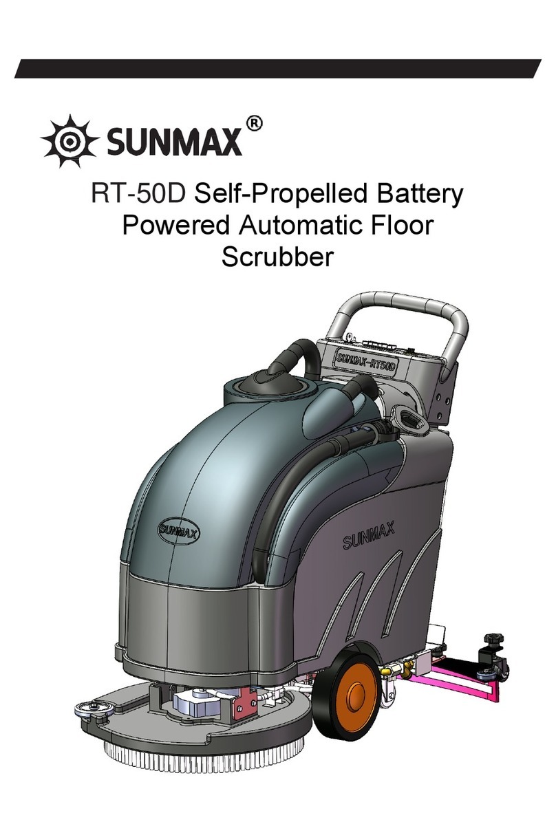
Sunmax RT-120 User guide

SUNMAX Hand Washing Machine
RT-120 Product Use and Maintenance Instructions

Symbols used in this manual:
Symbol "i" on the Opening Page
This symbol represents that you need to see this instruction manual.
Opening Book Symbol
This symbol represents that the operator needs to read this instruction manual before using the
machine.
Warning Sign
For the safety of the operator and the machine, please read the instruction of the parts marked
with this sign carefully.
Warning Sign
This symbol represents the danger of gas or liquid leakage.
Warning Sign
This symbol represents that the operator should take protective measures to avoid limb injury.
Warning Sign
This symbol represents that there is a danger of fire and keep away from open flames.
Warning Sign
This symbol represents that the packaged products need to be lifted by standardized means.
Processing Sign
Please read the parts marked with this symbol carefully.
1

Contents
Shipping Instructions for the Machine ................................................................................ 4
Main Introductions ................................................................................................................ 4
Applicable Ambient ............................................................................................................... 4
Technical Instructions ........................................................................................................... 5
Symbol Instructions Involved in the Machine .................................................................... 6
Safety Precautions ..................................................................................................................7
Preparation for Machine Use ................................................................................................9
1. Preparation before Unpacking the Machine......................................................................... 9
2. Methods for Moving the Machine...................................................................................... 10
3. Upper Control Panel Parts of the Machine ........................................................................ 10
4. Lower Control Panel Parts of the Machine ........................................................................10
5. Machine Assembly Drawing.............................................................................................. 11
6. Battery Models ...................................................................................................................11
7. Maintenance and Disposal of Batteries.............................................................................. 11
8. Loading and Unloading of Batteries ..................................................................................13
9. Operating Steps for Loading Batteries................................................................................13
10. Battery Connector and Battery Connection Methods....................................................... 14
11. Installation of Suction Scraper..........................................................................................15
12. Angle Adjustment of Suction Scraper.............................................................................. 15
13. Height Adjustment of Suction Scraper............................................................................. 15
14. Disassembly and Installation of Brush Tray.....................................................................16
15. Clear Water Tank for Water Injection.............................................................................. 17
16. Water Flow Setting of Clean Water Tank, and Cleaning and Replacement of Clean
Water Filter..................................................................................................................... 17
2

Machine Running..................................................................................................................19
17. Running Process............................................................................................................... 19
Operating Instruction of Operation Panel......................................................................... 21
18. Boot Interface................................................................................................................... 21
19. Operation Interface........................................................................................................... 21
20. Emergency Button Machine............................................................................................. 22
End of Machine Running..................................................................................................... 23
21. End of Machine Running..................................................................................................23
Machine Maintenance.......................................................................................................... 24
22. Daily Maintenance............................................................................................................24
23. Weekly Maintenance........................................................................................................ 24
24. Special Maintenance......................................................................................................... 24
Fault Handling...................................................................................................................... 26
25. Machine that Cannot be Started........................................................................................26
26. Brush with Insufficient Water Supply.............................................................................. 26
27. Suction Scraper that Cannot be Completely Sucked Dry................................................. 26
28. Machine that Cannot be Cleaned...................................................................................... 26
29. Generation of Excessive Foam......................................................................................... 27
30. Vacuum Cleaner that does not Work................................................................................27
31. Brush Motor that does not Work...................................................................................... 27
32. Fault Code.........................................................................................................................28
Machine Discarding..............................................................................................................31
Normal operation of the Machine....................................................................................... 31
Instructions for Use and Maintenance of Charger............................................................ 32
33. Use and Connection of Charger........................................................................................32
3

Shipping Instruction for the Machine
When the cleaning equipment is delivered to the customer, it must be inspected immediately to
ensure that all equipment mentioned in the shipping documents have been received, and to see if
the machine is damaged during transportation. In the event of an appeal, the receiving party
should determine the extent of the machine damage and promptly notify our customer service
department to ensure that we can resend you with the missing equipment and compensate for the
losses caused by our fault.
Main Introduction
This machine is a kind of floor cleaning equipment, which can clean any form of floors through
the high-speed rotation of the rotary brush and the detergent solution with high decontamination
ability. Its advantage lies in that it can collect all the dirt produced after cleaning, so that you do
not worry about the damage caused by the detergent solution when using it.
This machine can only be used for cleaning the floor. It is recommended to use it normally under
good working order, so as to keep the machine in the best condition. Therefore, we suggest that
you should read this manual carefully, and refer to it if you encounter difficulties during use. If
you really need help, you can contact our customer service hotline or dealer for consultation.
Applicable Ambient
This machine is specially used for cleaning indoor surfaces and floors of industrial, commercial
and public buildings.
This machine is not suitable for rain or underwater operation. It is forbidden to use this machine
to absorb dangerous dust.
4

Technical Instructions
Technical Description
Unit Of
Measure
machine
Standard
Brush Tray Motor
V/W
2x(24/500)
Push Rod Lifting Motor
V/W
1x24/15)
Driving Motor
V/W
1x24/500)
Vacuum Cleaner Motor
V/W
1x(24/1000)
Rotation Speed of Brush Tray
RPM
170
Outside Diameter of Brush Tray
inch
2x17"
Pressure of Brush Tray
LBS
110
Width of Suction Scraper
inch
38.8
Work Efficiency
SQ.ft
75000
Maximum Forward Speed
Km/h
5.5
Maximum Inclination at Full Load
%
10
Solution Tank
gal
31.7
Recycling Bin
gal
33
Rated Voltage of Batteries
V/Ah
12/120
Charging Time of Lithium Batteries
h
3~4
Charging Time of Lead-acid Batteries
h
8~10
Battery Lifetime
h
3.5~4
Net Battery Weight (Maximum)
LBS
176
Net Machine Weight (Excluding Batteries)
LBS
379
Net Machine Weight (Including the Machine and Batteries)
LBS
556
Total Weight of the Machine (Including the Machine, Batteries
and Packing Box)
LBS
666
Overall Dimensions of the Machine (Length x Width x Height)
inch
59.1x38.8x44.5
Dimensions of Packing Box (Length x Width x Height)
inch
61.8x36.0x50.6
5

Symbol Instructions Involved in the Machine
Symbol of Main Switch or Key Switch
This symbol is displayed on the dashboard, which is used to represent whether the machine is on
(ON-)or off (OFF-0).
Symbol of Audible Alarm
This symbol is used to represent an audible alarm button.
Symbol of Reverse Movement
This symbol is used to represent an operation of reverse gear button.
Symbol of Connected or Unconnected Brush Tray
This symbol is used to represent whether the brush tray is connected or not.
This symbol is used to represent the highest temperature of the filled water tank.
This symbol is used to represent the position of the drain pipe of the solution tank.
This symbol is used to represent the position of the drain pipe of the recycling bin.
This symbol is used to represent the maximum inclination.
6

Safety Precautions
In order to avoid injury to the operator or damage to the machine, please observe the
following regulations carefully.
Precautions:
Please read the label on the machine carefully. If there is any abnormality, please replace it
immediately.
The machine must be used by authorized and trained personnel. Do not make the inclination
of the machine exceed the allowable angle on the display screen.
This machine is not suitable for cleaning rough or uneven floor. Do not use the machine on
slopes.
If the power cord of the battery charger is damaged, please contact our authorized service
center immediately.
In case of danger, please press panic button on the command panel quickly.
During maintenance, please turn off the machine and disconnect the power cable.
Do not place the machine within the range where children can operate and play.
Please pay attention to the safety of other people around you, especially children, when using
the machine.
Please use the brush provided by this machine or the brush selected in the "Selection and Use
of Brush" in the operation manual. Do not use other brushes to avoid accidents.
Precautions:
This machine is not suitable for children, disabled people, mental patients or people who
lack knowledge and experience.
This machine must not be used outdoors or in a humid environment, and direct exposure to
rain is strictly prohibited.
The storage temperature of this machine is between-25℃ and 55℃. Do not store it outdoors
in humid environment for a long time.
The use conditions are room temperature 0℃-40℃ and relative humidity 30%-90%.
The power cord socket (plug-in version) of this machine or the power cord for battery
charger (rechargeable version) must be floored correctly.
Please operate this machine at an appropriate speed.
Do not use this machine as a means of transportation.
This machine will not produce harmful vibration.
Do not use the machine in flammable and explosive environment.
Do not use this machine to collect flammable liquids.
Do not use this machine to collect dangerous powder.
Do not mix different types of detergents, which may react to produce harmful gases.
This machine is not suitable for cleaning carpets.
Do not put any liquid containers on the machine.
When the machine is stationary, do not use brushes to avoid damage to the floor.
In case of fire, please use powder fire extinguisher and never use water to put out the fire.
Do not knock against the scaffold, and lest it fall. Operators must always be equipped with
corresponding safety measures (including gloves, shoes, helmets, goggles, etc.) during use.
7

This machine can be cleaned and dried at the same time. Do not let other people near it
during the operation. If the floor is still wet, relevant signs should be placed for reminding.
If the machine does not work properly, please check whether it is caused by failure to carry
out routine maintenance. Otherwise, please contact the technical assistance center for helping.
If you need to replace any parts, please buy original parts from our authorized dealers or
retailers.
After carrying out the maintenance, please connect the relevant power supply equipment.
Before using this machine, please check whether all the covers identified in the operation
and maintenance instructions are normal.
Do not take out the relevant protective device unless it is necessary for maintenance (please
refer to relevant paragraphs).
Do not spray water or high-pressure water gun directly to clean this machine, and cleaning
with corrosive liquid is strictly prohibited.
In order to prevent scaling in the filter of the solution tank, it takes several hours to use the
machine after adding the cleaner into the tank.
Do not use acidic or alkaline liquids, because it may damage the machine or hurt others.
Please ensure that the machine is maintained by professionals every year.
Please strictly abide by local laws and regulations when dealing with the waste generated by
the machine.
When your machine has reached its service lifetime, please dispose of its materials
(especially oil, batteries and electronic components) in an appropriate way, and please
consider that the materials of this machine are made of 100% recyclable materials.
Please remove batteries before handling the machine, and handle the batteries safely
according to local laws and regulations.
8

Preparation for Machine Use
1. Preparation before Unpacking the Machine
The machine is packed in a special wooden box (Fig.1) for
forklift loading and unloading.
The package cannot be placed on the top of the forklift.
The total weight of the machine and package is 666LBS.
The size of the package in LxWxH is as follows:
L:61.8”
W:36.0”
H:50.6”
1. The outer package must be removed.
2. The floor washer (Fig.2) has been fixed on the tray for the
wooden box, and the tray for the wooden box contains wedges
to prevent the machine from moving.
3. Wedges must be removed.
4. The machine must be removed from the tray for the wooden
box by using the unloading rack and pushed back. Before
taking down the machine, the suction scraper must be lifted
(Fig.3), and then the handle (1) must be lifted upward.
5. Shelves of containers shall be reserved for later
transportation.
Note: If the products are transported in cardboard boxes, handling the packaged products with
proper lifting means meeting the legal requirements.
Note: During the operation of the machine, please ensure that there are no people and other
objects around the machine.
9

2. Methods for Moving the Machine (Fig. 4)
1. Check that the recycling bin is empty, and
empty it if necessary.
2. Check that the brush head and suction
scraper are in the lifting position.
3. Place it on the container rack by using the
chute.
4. Check that the key switch is "OFF" and then
remove the key.
5. Use wooden wedges to fix the machine on
the container rack.
6. Use electronic brake.
3. Upper Control Panel Parts of the Machine
(Fig. 5)
1. Driving Button
2. Liquid Crystal Display Of Batteries
3. Start
4. Dust Absorption
5. Water Quantity Plus
6. Forward / Backward
7. Water Quantity Minus
8. Downloading and Unloading Brush
9. Electric Lock OFF/ON
10. Speed Regulating Knob
11.ECO
12. Uploading and Unloading Brush
4. Lower Control Panel Parts of the
Machine (Fig. 6)
13. Emergency Button
14. Charging Plug
15. Handle Rod of Suction Scraper
10

5. Machine Assembly Drawing (Fig. 7)
1. Handle
2. Control Panel
3. Drain Pipe of Sewage
Tank
4. Handle Rod of Suction
Scraper
5. Pull Rope of Suction
Scraper
6. Water Level Pipe of Clear
Water Tank
7. Sewage Suction Pipe
8. Height Adjustment Handle
of Suction Scraper
9. Suction Scraper
10. Angle Adjustment Handle
of Suction Scraper
11. Installation Handle of
Suction Scraper
12. Supporting Wheel
13. Anti-collision Wheel
14. Water Injection Port of
Clean Water Tank
15. Batteries
16. Brushes
17. Shield
18. Clean Water Tank
19. Sewage Tank
20. Handle of Tank Cover
21. Sewage Tank Cover
22. Brush Tray
23. Electromagnetic Control
Valve
24. Brush Tray Motor
25. Driving Wheel
26. Auxiliary Wheel
27. Filter
6. Battery Models
1. To start the machine, you must use maintenance-free batteries, sealed batteries with gel
technology, and other types of batteries are not allowed.
2. The battery must meet the following models and standards such as CEI EN 60254-1: 2005-12
(CEI 21-5) and CEI EN 60254-2: 2008-06 (CEI 21-7).
3. In order to obtain good performance of the machine, we recommend using the batteries in 12V-
120Ah/C5.
7. Maintenance and Disposal of Batteries
1. Please refer to the instructions of the battery supplier to keep and charge the batteries. The new
batteries should be fully charged before being used for the first time. The new batteries can be
deeply charged and discharged for 5 times.
2. Please pay attention to the choice of battery charger, because the model and capacity of battery
charger are different, please choose a professional charger.
11

3. When the batteries are close to their service lifetime, it must be taken out of the battery room
by specialized personnel with the help of professional equipment. Discarded batteries are
classified as dangerous discarded items, so we must choose a suitable way to dispose of them!
Warning: It is recommended that you use protective gloves to avoid serious injuries to your
hands.
Warning: It is recommended to use a load tool that is suitable for the dimensions and weight
of the instrument to take out the batteries.
12

8. Loading and Unloading of Batteries
The batteries should be installed in a special container under the seat. They need to use lifting
tools with suitable load and volume for loading and unloading. These batteries must also meet the
CEI 21-5 standard. The dimensions of the batteries are 340mmx175mmx290.
Warning: Regarding the storage and daily charging of the batteries, the instructions of the
battery supplier must be carefully followed. All installation and storage operations shall be
carried out by relevant technicians.
Warning: It is recommended to use sealed batteries to prevent acid leakage!
Warning: It is recommended to always use protective gloves to avoid serious injuries to
your hands.
9. Operating Steps for Loading Batteries (Fig. 8)
1. Ensure that the sewage tank (A) has
been emptied.
2. Open the sewage tank (A).
3. Place the batteries (C) in the battery
room of the clean water tank (B), and
place the positive and negative poles of
"+" and "-" oppositely.
Notes:
1. Please ensure that the red terminal (+) is connected to the positive terminal (+) and the black
terminal (-) is connected to the negative terminal (-). If the connection is not correct, the machine
will run incorrectly.
2. If the above operations are not followed, the batteries will be damaged and may explode.
3. It is necessary to spray protective lubricant on battery terminals, and put cord terminal
protective sleeves on all terminals.
Note: It is recommended to use lifting tools with suitable load and volume for loading
and unloading.
13

10. Battery Connector and Battery Connection Methods (Fig. 9)
1. Connect the positive and negative poles of
the batteries in series with the jumper cord
provided.
2. Connect the connector of the batteries to the
positive and negative poles to obtain a voltage
of 24V.
3. Connect the connector cord of the batteries
(1) to the machine connector (2).
4. Rotate the seat bracket to its working
position.
Warning: All installation and maintenance operations must be carried out by professionally
trained professionals.
14

11. Installation of Suction Scraper (Fig. 10)
1. Lift the handle rod (A) of the suction scraper
and move it upward.
2. Place the suction scraper (B) under the
suction scraper mounting seat (C) and align it
with the two mounting holes of the mounting
seat.
3. Place two 10 flat pads (D) on the suction
scraper mounting seat (C) and align them with
the two mounting holes of the mounting seat.
4. Place two M10 star handles (E) on the flat
pad (D) and align them with the mounting
holes of the two mounting seats, then align
them with the two threaded holes of the suction
scraper, and finally tighten the star handles.
5. Insert the sewage suction pipe (F) into the
connector in the middle of the suction scraper.
12. Angle Adjustment of Suction Scraper (Fig. 11)
In the process of operation, the rubber scraper behind the suction scraper must be slightly tilted
backwards (about 5mm) to ensure the overall length to be uniform. If it is necessary to bend the
middle rubber scraper, the suction scraper must be tilted as follows:
1. Turn a star handle (A) clockwise to make the rubber scraper of the suction scraper in the
middle part bend continuously, and adjust it until the rubber scraper leans back slightly (about
5mm).
13. Height Adjustment of Suction Scraper (Fig. 11)
The height of the scraper must be adjusted according to the wear state of rubber, which mainly
includes the following steps:
1. Rotate two star handles (B) clockwise or counterclockwise to adjust the height of the rubber
scraper of the water suction scraper. When rotating clockwise, the rubber scraper will rise, and
when rotating counterclockwise, the rubber scraper will fall. If the rubber scraper is worn, rotate
counterclockwise to adjust the two star handles (B).
Note: It is necessary to use protective gloves for these operations to avoid touching sharp
edges or tips of metal objects.
15

14. Disassembly and Installation of Brush Tray (Fig. 12. 13)
1. Please check that the key switch (9) of the machine control panel is in the "ON" state.
2. The speed regulating knob (10) must be set to the lowest gear counterclockwise.
Note: This speed regulating knob must be turned to the lowest position, otherwise the action of
loading and unloading the brush tray will not be performed.
3. If you want to remove the brush tray from the brush tray cover (A), please just press the brush
unloading button (8) on the control panel (the green light is on), and the brush tray will be
automatically removed without manual disassembly.
4. If you want to install or replace the brush tray, firstly, the brush tray cover (A) is in a raised
state, then manually place the two brush trays (B) in the center position corresponding to the
rotating shaft of the brush tray cover (approximately in the center position, but not too far away
from the center position of the rotating shaft), and then press the brush button (12) on the control
panel (the green light is on), so that the brush tray cover (A) will brush. Then please visually
check whether the brush tray is completely covered in the brush tray cover (A). If the brush tray
is not covered in the brush tray cover (A), you can use auxiliary tools to move the brush tray to be
completely covered by the brush tray cover (A). If the brush tray cannot be adjusted, you can
press the brush button (12) again until the brush tray cover (A) will automatically rise after the
brush installation program is automatically executed. After the brush tray is successfully installed,
the brush tray will be automatically installed and raised without manual installation and lifting.
Warning: Do not let people or things near the brush during operation.
Note: Please pay attention to whether the brush is inserted normally. Otherwise, the machine will
suddenly move irregularly during operation.
Caution: Protective gloves must be used for these operations to avoid contact with sharp edges or
tips of metal objects.
16

15. Clear Water Tank for Water Injection (Fig. 14. 15)
1. Please check whether the valves (D) of the water pipes on both sides of the water tank have
been closed, and if the handle of the valve is in the vertical direction, it will be closed.
2. Then you should open the cover (B) on the clean water tank (A).
3. The maximum capacity of clean water added to the clean water tank is 120 liters, and the
temperature of the added clean water cannot exceed 50℃.
4. Please add the liquid detergent according to the concentration and method shown on the label
by the manufacturer. In order to avoid the possibility that excessive foam may damage the
vacuum cleaner motor, please add it according to the minimum amount required by the detergent.
The amount of detergent can also be measured by the cover that comes with the clean water tank,
and the cover can also be used as a measuring cup.
5. Cleaning chemicals, acidic or alkaline cleaners can be added, but it is required not to contain
oxidants, chlorine or bromine, formaldehyde and mineral solvents.
16. Water Flow Setting of Clean Water Tank, and Cleaning and Replacement of Clean
Water Filter (Fig. 16)
1. Adjust the fresh water flow according to the floor condition, and the buttons on the control
panel need to be adjusted as water quantity plus (5) and water quantity minus (7).
2. Regularly clean the dirt in the filter (E) under the clean water tank according to the frequency
of use (it is recommended to clean it once a week).
Warning: Every time the clean water tank solution is filled, the clean water tank must be
completely emptied.
17

Warning: Please determine whether the detergent is suitable for this machine according to
the label instructions of the detergent manufacturer. Do not choose products or solvents without
acidity and alkalinity labels. This machine can use acidic or alkaline cleaners with PH value
between 4 and 10, but it is required not to contain oxidant, chlorine or bromine, formaldehyde
and mineral flux.
Note: Please be sure to use low-foam detergent. In order to avoid a lot of foam, please inject
a little defoaming solvent into the recycling bin before cleaning. Never use pure acid.
Warning: When handling acidic or alkaline detergents, please wear protective gloves to
avoid serious injury to your hands.
18

Machine Running
17. Running Process (Fig. 17. 18. 19)
Before starting the work, the following preparations must be made:
1. Please check whether the sewage tank is empty, and if not, you should empty it.
2. Please check whether the sewage pipe has been hung in the buckle at the upper end of the
sewage tank.
3. Please turn the speed regulating knob (10) to the lowest state.
4. Please check whether the battery connector is connected to the batteries.
5. Please check whether there is a brush tray on the machine. If not, you should start the machine
before installing it.
6. Please check whether the emergency stop button switch (13) is turned on, if not, it needs to be
turned on.
7. Please turn the key switch (9) to the position “ON” on the machine control panel, and the
display screen on the instrument panel will be displayed immediately.
8. Please check whether the electronic brake is available.
9. Please check whether the valves (D) on both sides under the clean water tank have been opened.
If the handle of the valve is horizontal, it will be open.
10. Please turn the speed knob (10) higher.
11. Please hold the handle of the suction scraper with your hand and move it down, so that the
suction scraper will fall down.
12. Please press the start button (3) once (the green light is on), and the dust suction button (4)
will automatically activate (the green light is on), and then press the two driving buttons (1) on
the handle with both hands, and the machine will start to move forward. The solenoid valve will
start to work and start to distribute detergent solution. If you press any driving button (1) on the
handle, the speed will be reduced by 50% to drive. If you want to save a little electricity, ECO(11)
mode can be used.
13. If you want the machine to run in the reverse direction, you must lift the suction scraper, and
then press the reverse button (6) on the control panel. Other operations are consistent with the
forward operation.
Warning: If you want to stop the machine, you can just remove your hands.
Warning: After the start button (3) is pressed, the brush tray will be automatically put down.
After both hands hold down the driving button (1), the solenoid valve will start to work and start
19
Table of contents
Other Sunmax Scrubber manuals
Popular Scrubber manuals by other brands

ServiceMASTER Clean
ServiceMASTER Clean KING COBRA 1200 PRO 120V Information & operating instructions

Tennant
Tennant 5500 Complete Operator and parts manual

HSS Hire
HSS Hire 439 Operating & safety guide

Numatic
Numatic TTV - 4555/100T Owner's instructions

Nederman
Nederman Single Exhaust Extractor instruction manual

IPC
IPC CT40 Series Operator's manual

Tennant
Tennant T5E Operator's manual

Clarke
Clarke Scrubtec Boost 70 Operator's manual

Nilfisk-Euroclean
Nilfisk-Euroclean SC800 Instructions for use

Blue Star
Blue Star 607047 Operator and parts manual

Ice
Ice RS28-OB Operator's & parts manual

Pacific
Pacific ScrubMaster 20B Operating & maintenance instructions