CAUTION
DETERMINING WHICH INSTALLATION
METHOD TO USE
ELECTRICAL JUNCTION BOXES
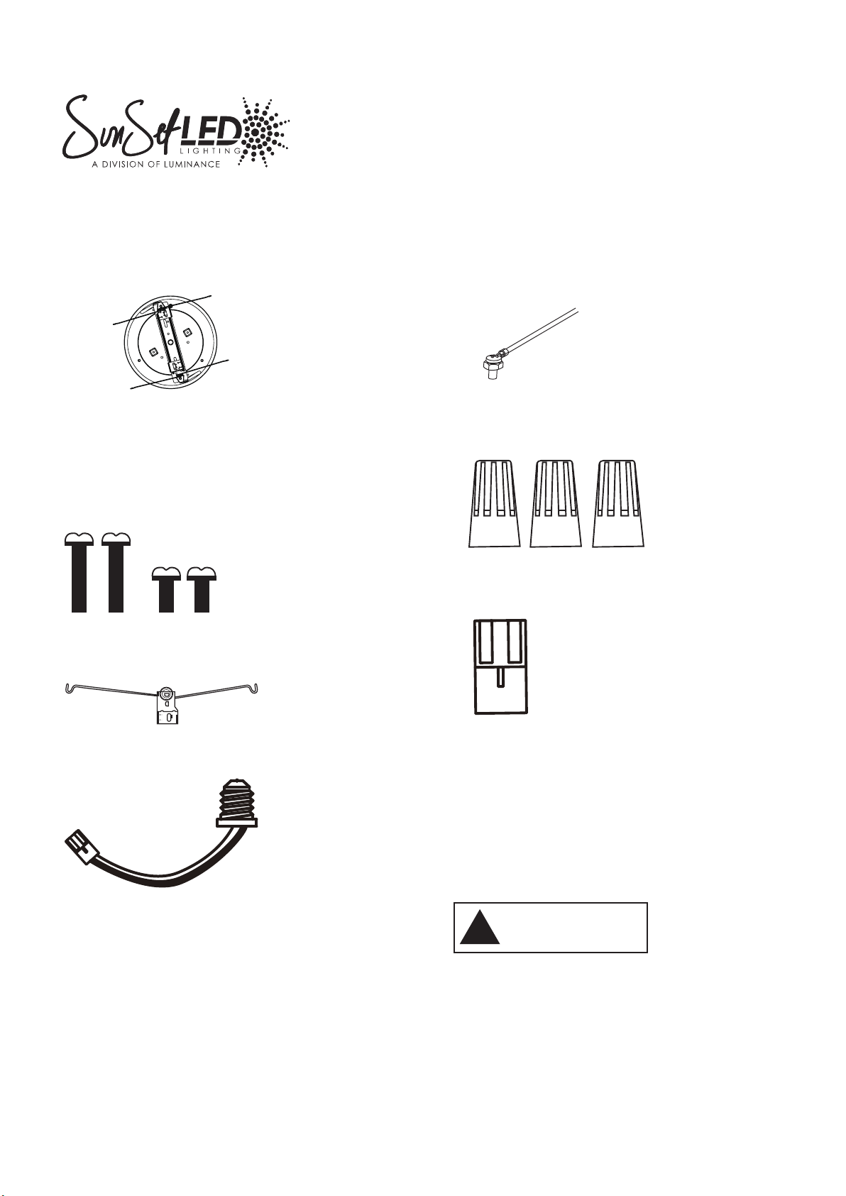
This module can be mounted to recessed mounted
standard junction boxes with junction box bracket or
installed into 5 inch and 6 inch recessed housings with
torsion spring receivers.
Risk of electric shock.Disconnect power at fuse or
circuit breaker before installing or servicing.
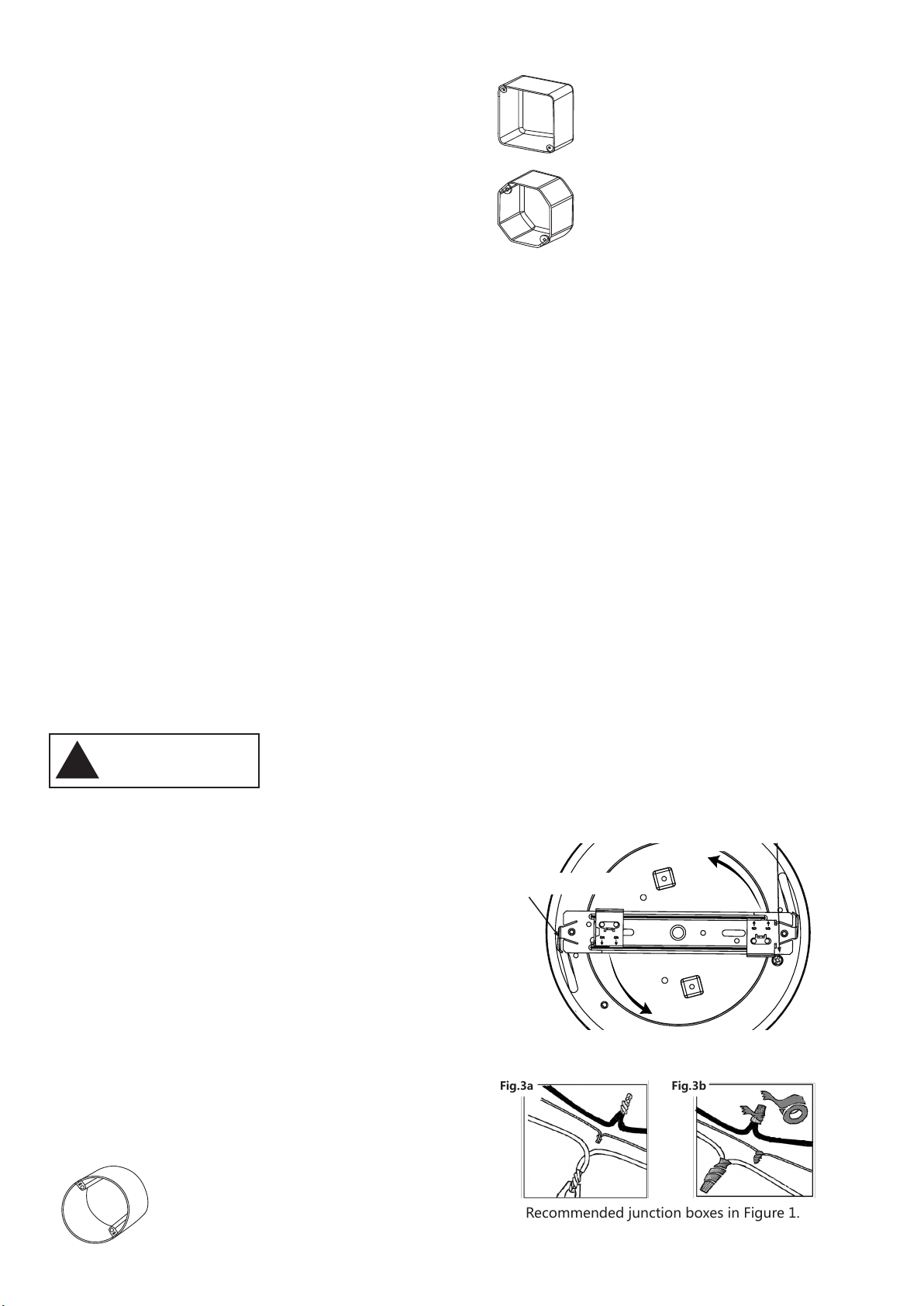
NOTE: The module installs onto many standard
recessed ceiling and wall mounted junction boxes
(Fig.1)
- 4" octagon; 2 1/8" Deep
- 4" square; 2 1/8" Deep
- 4" round; 2 1/8" Deep
(Box types and site condition vary. Installer to ensure
compatibility at fit, wiring and proper mounting.)
The junction box must be a minimum 2 1/8 inch in depth
for proper installation. Recommended boxes shown in
Fig 1.
RECESSED DOWNLIGHT HOUSINGS
WARNING:Risk of Fire or Electric Shock. For Use only
with the following recessed housings.
● The DSK6 LED module comes with a dedicated
LED connector for California Title 24 Compliance
and is ETL Listed for installation into recessed
LED housings.
●The DSK6 series also includes an E26 Edison
screw base adapter to accommodate standard
screw base recessed housings. The DSK6 is
ETL Listed and Classified for retrofit in 5”& 6”
Downlight housings:
Mounting to a junction box:
1. Remove 2 retaining screws next to J box mounting
bracket from the LED module (see Fig. 2).
2. Remove the J box mounting bracket by holding the
module and rotating the bracket counterclockwise.
3. Connect the Supply Wire Adapter to the house
supply wires. Using the included wire nuts, connect
adapters black wire to hot supply wire and connect
adapters white wire to supply neutral wire. Connect
the ground wire (attached to the bracket) to the
ground wire in the junction box using the included
wire nuts (Fig. 3).
Mounting to recessed mounted standard
junction boxes
Fig.1
Fig.2
●Connect fixture to a 120volt,60Hz power source.
Any other connection voids the warranty.
●Fixture should be installed by persons with
experience in household wiring or by a qualified
electrician.The edectrical system,and the method of
electrically connecting the housing to it,must be in
accordance with the National Electrical Code and local
building codes.
●This device complies with Part 15 of the FCC Rules.
Operation is subject to the following two conditions:
(1) this device may not cause harmful interference,
and
(2) this device must accept any interference received,
including interference that may cause undesired
operation.
●Do not make or alter any open holes in an enclosure
of wiring or electrical components during kit
installation .
SAVE THESE INSTRUCTIONS AND WARNINGS.
Disk Light is designed for dimming with many 120V
Leading Edge(LE) and Trailing Edge (TE) phase control
dimmers. Dimming capability may be enhanced with
select dimmers that feature low end trim adjustment.
(Consult dimmer manufacturer for specific load
compatibility and application information. (Note some
dimmers require a neutral in the wallbox.) For the
latest Disk Light product information , please refer to
specifications online at www.globaluxlignting.com.
WARNING
!
Round-2 1/8” minimum depth
Square-2 1/8” minimum depth
Octagonal-2 1/8” minimum depth
For j-box mounting,remove the two
retaining screws
Rotate j-box bracket counterclockwise
to remove from retrofit
Recommended junction boxes in Figure 1.
Fig.3
Fig.3a Fig.3b
RIS02332/4