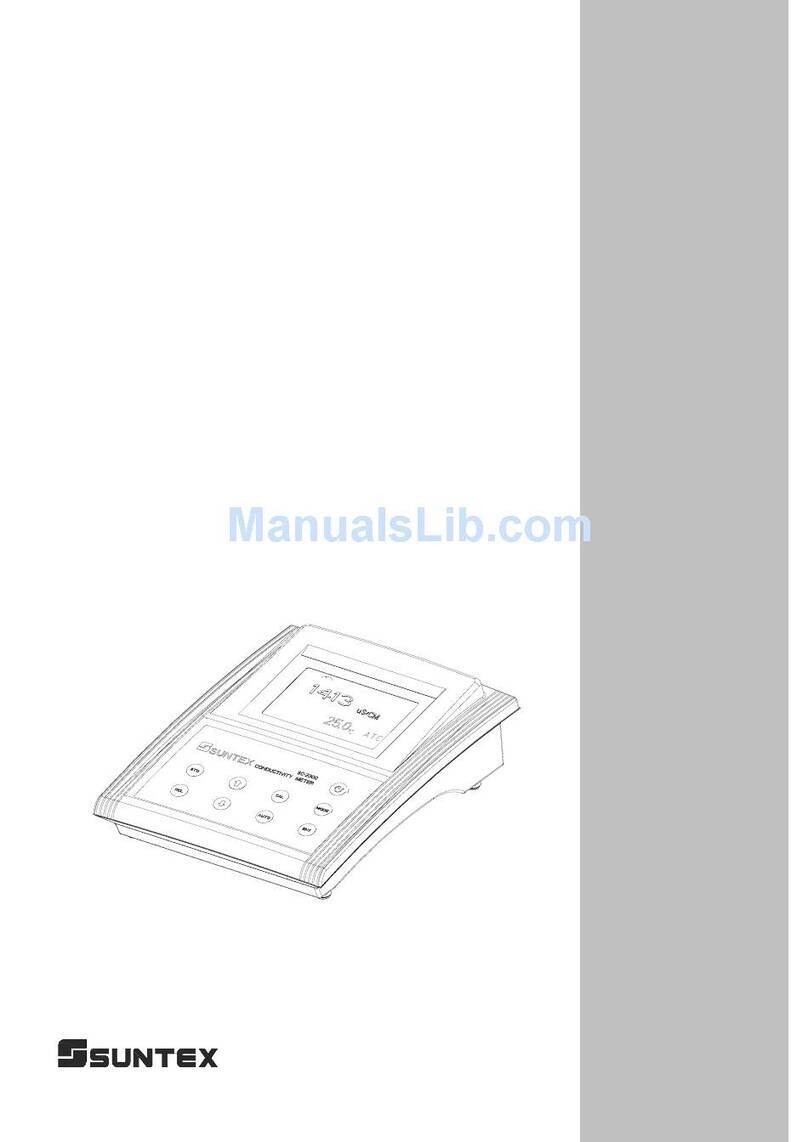
Suntex SC-110 User manual

5
Portable
Conductivity/
Resistivity
Meter
SC-110
Operation
Manual

i
ContentTable
1. Specifications 1
2. Configuration
2.1 Display 2
2.2 Socket 2
2.3 Keypad 3
3. Operation
3.1 Measurement 4
3.2 Measurement function and file bit shift 4
3.3 Temperature function and compensation 5
3.4 Auto Read 5
4. Settings
Block diagram of settings 6
4.1 Parameter settings 7
4.1.1 Entry of set-up mode 7
4.1.2 Settings of measurement mode 7
4.1.3 Settings of data deletion 7
4.1.4 Settings of baud rate (BAUD) 8
4.1.5 Settings of system time 9
4.2 Deletion of all stored data 10
4.3 System reset 10
Block diagram of calibration and temperature compensation settings 11
4.4 Settings of calibration parameter 12
4.4.1 Electrode coefficient and calibration parameter 12
4.4.2 Standard solution calibration parameter 13
4.4.3 Temperature compensation coefficient 13
Block diagram of operations in measurement mode 14
4.5 Auto/manual data storage 15
4.5.1 Auto storage 15
4.5.2 Manual storage 15
4.5.3 Data full 15
4.6 Data readout and output 16
4.6.1 Auto transmission 16
4.6.2 Manual readout and transmission 16
5. Calibration
Block diagram of Calibration 20
5.1 Standard solution preparation 21

ii
5.2 Calibration mode 21
5.3 Entry of calibration mode 21
5.3.1 Electrode coefficient calibration 21
5.3.2 Standard solution single-point calibration 21
5.3.3 Standard solution five-point calibration 22
6. Instruction set for RS232 23
7. Alternative fittings 23
8. Failure recovery 24
9. Maintenance 25

1
1.Specifications
Mode SC-110
Function µS/mS/MΩ/Salinity/TDS/Temp.
Cond. 0.00 uS/cm ~ 200.0 mS/cm in 5 measuring ranges for manual or auto switch
Res. 0.00~100.00 MΩ- cm
Salt 0.0~70.0ppt
TDS 0~2000ppm
Range
TEMP -10.0~110.0°C
Cond. 0.01µS/cm
Res. 0.01 MΩ-cm
Salt 0.1 ppt
TDS 1 ppm
Resolution
TEMP 0.1°C
Cond. ±0.5%(±1Digit)
Res. ±1%(±1Digit)
Salt.±0.5%(±1Digit)
TDS ±0.5%(±1Digit)
Accurac
y
Temp. ±0.2°C(±1Digit)
PT-1000 or NTC 30K auto recognition
Temperature
Compensation Auto / Manual selectable
Temperature
Coefficient Non-linear / 0.00 ~ 10.00 % Linear
Ref. Temperature Tref 25℃
Manual calibration Single point known standard solution or electrode constant calibration
Standard solution
calibration Single or up to 5-point known standard solution calibration; default five
standard solution 10/84/1413 uS/cm & 12.88/100 mS/cm adjustable
RS232 interface YES
Output Data logging 450 sets (measuring value, temp., date, time & ID)
Ambient
temperature 0~50°C
Storage
Temperature -20~70°C
Display 1/2” LCD
Power 4 x AA battery
Battery Around 350 — 1000 hrs according to measuring range; auto shut-off within10
minutes of no use
Protection Type IP65
Certified to CE
Dimension
(L x W x H) 185 x 98 x 38mm
Weight 0.35Kg

2
2.Configuration
2.1 Display:
2.2 Socket:
Set-up mode Measurement mode
Measurement unit
Auto temperature
compensation
Time reminder
Auto read
Calibration mode
Data storage mode
Low battery
reminder
Data read
/Transmission mode
Data Storage ID
number
Storage ID
Transmission
speed
Conductivity
electrode socket
RS232 interface socket

3
: Power switch. Push it to power on and push it again to power off. Auto shut-off
within10 minutes of no use
: Cond./Res./Salt/TDS measurement shift key; pushing it at any time will allow
backing to the measurement mode.
: Enter calibration mode.
: Key for auto read in measurement mode. Push one time for startup and push again for
cancellation.
: Upward or leftward key. For value adjustment, push it to increase the speed.
: Downward or rightward key. For value adjustment, push it to decrease the speed.
: (ENTER) Input, confirm, execute, and RS-232 manual output
: (Recall) Manual data read startup key and value read selection key.
: (Store) Manual data storage startup key
: Enter system parameter set-up, see 4.1
: Delete all stored data, see 4.2
: System reset, see 4.3
: Shift among the five manual modes and the auto mode. See 3.1
: Enter calibration parameter settings. See 4.4
: Enter auto continual storage settings. See 4.5
: Enter auto continual transmission settings. See 4.6
2.3 Keypad:
+
+
+
+
+
+
+

4
3.Operation
3.1 Measurement:
Push key to start up the instrument. It will automatically enter the measurement mode
of final operation and begin to measure.
3.2 Measurement function and file bit shift:
1. Push key to shift among Cond., Salt, and TDS in Cond. Mode. This function is
unavailable in Res. mode.
2. Push + keys to shift among the five manual shifts and the auto shift. After
entering auto mode, AUTO characters will disappear after 3 seconds.
Remark: Before measuring salt and TDS, please finish the calibration according to the
conductivity calibration steps, and then set the factor value according to the standard
solution of salt and TDS.
Push to shift
Salt unit
Push to shift
TDS unit
Push toadjust
the salt value. Note:
Factor range is 0.4~1.5
Push toadjust
Total Dissolved
Solids. Note: Factor
ran
g
e is 0.4~1.5
Push +
Push +
Push
Push +
Push +
Push +
Push +

5
3.3 Temperature function and compensation:
1. ATC: Auto judgment of whether there is temperature probe and recognition of NTC30K
or PT1000. Push or to adjust the temperature within in ±5℃. At the same time,
push keys to back to the original value.
2. MTC: Enter MTC 25℃automatically when there is no temperature probe. Push
or to adjust the temperature. At the same time, push keys to back to the
default value 25.0℃.
3. Temperature compensation: Because the temperature of the to-be-tested solution may not
be 25℃, for standardization, the conductivity value of solution not at the temperature of
25℃will be calculated to that of solution at the temperature of 25℃. This is temperature
compensation.
4. According to the temperature coefficient required by the measurement, three kinds of
temperature compensation can be applied: Lin, nLin, and non compensation (0.00%). See
the setting method in 4.4.3, and the user can set as needed.
5. Temp. Coefficient (called as TC for short), the conductivity value of the solution will
increase as the temperature rises at a different rate. See the relations as follows:
C25 Conductivity at 25℃
Ct Conductivity at T℃Formula 1: Ct = C25 { 1+β( T – 25 ) }
T Temp. of the tested solution
βTemp. Coefficient Formula 2: β= ( Ct-C25 ) / { C25 ( T-25 )}
6. How to measure the TC of the tested solution: If the user wants to get a more accurate
value, the above formula can be applied to measure the TC of the tested solution and set
an appropriate TC on the machine. Take 0.01N Kcl as an instance, set the TC as non
compensation (0.00%) in the machine. Control the same tested solution respectively at
5℃and 20℃. The value 1413μS tested at C25 is just the conductivity of the solution at
25℃; and the value 1278μS tested at Ct is just the conductivity of the solution at 20℃.
According to formula 2, β=1.91%.
3.4 Auto Read:
In the measurement mode, push to start up and push to read. Then, push
Enter to make the next measurement. Push or at any time will allow backing to
the measurement mode.
Auto Read symbol twinkles
for about 10 seconds.
Auto Read symbol stop twinkling
and a value will appear after the
measurement is stable.
Back to the measurement
Push or

6
4. Settings
Block diagram of settings
↓: Enter key
→: Downward key for right
←: Upward key for left
Data overcast settings Baud rate settings
Push o
r
to select auto
overcast or
cancel overcast
Push or
to select other
transmission
speed: 1200,
2400, 4800 or
9600
Push Store+Powe
r
,
Loose Power+Store
To delete all stored
data
Push CAL+Powe
r
,
Loose Power+CAL
System reset
Push Mode+Powe
r
Loose Power+MODE to
enter the measurement
mode
Settings of measurement
mode
Power off
System time settings
Push or to modify the minute
Push or to modify the year
Push or to modify the month
Push or to modify the day
Push or to modify the
Push o
r
to select
conductivity or
specific resistivity

7
4.1 Parameter settings:
4.1.1 Entry of set-up mode:
In the power-off status, push first and then; after that loose first and
then to enter the parameter set-up mode. Use to select.
4.1.2 Settings of measurement mode:
4.1.3 Settings of data deletion:
Enter “Settings of data deletion”
Push or to select
MΩ-cm、uS/cm
Push to enter
Push to confirm
Push to enter
Enter “Settings of baud rate”
Push or to select auto
overcast or cancel auto overcast
Push to confirm

8
4.1.4 Settings of baud rate (BAUD):
Enter “Settings of RS-232 baud rate”
Push to enter
Enter “Settings of system time
Push to confirm
Push or
to select Push or
to select
Push or
to select

9
4.1.5 Settings of system time:
Enter “Settings of system time”
Push to enter
Push or to modify the year,
push to confirm
Push or to modify the month,
push to confirm
Push or to modify the day,
push to confirm
Push or tomodifythehour,
push to confirm
Push or to modify the minute,
push to confirm
Back to “Setting of measurement mod,
or push to back to measurement mode

10
4.2 Deletion of all stored data:
In the power-on status, push first and then; after that loose first and then
to enter the data deletion mode.
4.3 System reset:
In the power-off status, push first and then; after that loose first and
then to enter the system reset page.
Factory defaults:
Data deletion settings: Auto
(BAUD) settings: 4800
Data transmission settings: read the stored data on the display (Sto diSP)
Back to the measurement
Push to confirm to delete all stored
data or push to back to the
Push to confirm the system reset;
or push to back to the

11
Block diagram of calibration and temperature compensation settings
Settings in specific resistivity mode
Measurement mode
Power on
Calibration and temperature
com
p
ensation settin
g
s. Push Enter+CAL
Settings in conductivity mode
Measurem
Power on
Push Enter+CAL
Measurement temperature
Electrode coefficient
calibration settings Standard solution
calibration settings
Measurement temperature
coefficient settings

12
4.4 Settings of calibration parameter:
In the power-on status, push first and then to enter set-up mode of calibration
parameter. Use to select.
4.4.1 Electrode coefficient and calibration parameter:
(Only suitable when the measurement unit is conductivity)
Push to confirm
Back to measurement mode
Push to enter the settings
of calibration temperature
Push to confirm
Push or
to select
Push or to set the temperature
Push or
to select
Push to confirm

13
4.4.2 Standard solution calibration parameter:
(Only suitable when the measurement unit is conductivity)
4.4.3 Temperature compensation coefficient:
Push or
to select
Push to confirm
Back to measurement mode
Push to confirm
Push to confirm
Back to measurement
Push to confirm
Push or
to select
Push or to set the temperature
Push or
to select
Push to confirm

14
Block diagram of operations in measurement mode
Appear recently stored
Push or to close
Read the ID, and push or
to in
q
uire other data throu
g
h ID
Back to the
measurement
mode
Read the stored
y
ea
r
Read the stored date
Read the stored time
If the Auto and Store
icons shine, it means
that the data is stored
In case of data full
unable to store,
Store will twinkle
Back to the
measurement
mode
Appear the
ori
g
inal ID
Push or to
set the ID number
Push or
to set the minute
If the Auto and Store
icons shine, it means
that the data is stored
Continual
measurement and data
Cancel continual
stora
g
e
Data store full
Transmissi
Power on
Stora
g
e
Auto store
Push Enter+Store
Appear the original ID
Back to the
measurement
Manual
store push
After
transmission,
back to the
measurement
mode
automatically
Auto transmission
Push Enter+Recall
Continual
transmission
The stored data
is transmitted
The stored data is
transmitted through RS232
The calibrated data is
transmitted to the dis
p
la
y
The stored data is
transmitted to the display
Manual read and transmission
Push Recall to shift circularl
y
amon
g
4 modes
CEL
L
direct Std simple point
calibration
Std five point
calibration
Back to
the
measurem
ent mode
Back to
the
measurem
ent mode
Back to
the
measurem
ent mode
After
transmission,
back to the
measurement
mode
automatically
Push or to
set the second
Push or to
set the ID number
Push or to
set the minute
Push or to
set the second
Push or to
modify the

15
4.5 Auto/manual data storage:
4.5.1 Auto storage:
In the measurement mode, push first
and then to enter the auto continual
storage set-up mode.
4.5.2 Manual storage:
In the measurement mode, push to
enter manual store page.
4.5.3 Data full:
When the data is full to store, the
display will shine as a reminder, and
five seconds later, it will back to the
original measurement mode.
According to step 4.2, delete all the data.
In case of auto overcast, there will no
reminder of data full.
Back to the measurement
Push to confirm
Push or to set ID number;
Push to confirm the storage
Back to measurement mode
Push to confirm
Push or to set ID
number; Push to confirm
and enter settings of automatic
Push or to set the minute,
and push for confirmation and
settings of second
Push + or push to
cancel the auto store mode
If the Auto and Store
icons shine, it means
that the data is stored
Push or to set the seconds,
and push for confirmation. (The
minimum value is 5 seconds)

16
4.6 Data readout and output:
4.6.1 Auto transmission:
In the measurement mode, push first
and then to enter auto transmission.
4.6.2 Manual readout and transmission:
In the measurement mode, push to shift
among 4 modes circularly, and push to
enter.
A. Read the stored data on the display
Push or to set the minute,
and push for confirmation and
enter the second setting.
Back to measurement mode
Push or tosettheseconds,
and push for confirmation.
(The minimum value is 5 seconds)
If the Auto and Store icons
shine, it means that the data
is stored automatically
Push to enter, and the recently
stored data will appear
Push or to modify the
inquiry site. Push to confirm.
Read the ID and push and to inquire
other data according to the Id. Push to
read the data value and year.
Push to read the stored date
Push to read the stored time
Push + orpush
to cancel the auto store mode
Back to measurement mode
Push
Push to read the store temperature

17
B. Transmit the stored data through RS-232
Transmit all stored data through RS-232
C. Read the calibrated data on the display
C.1 Read the CELL calibrated data (when
the calibration parameter is set as
CELL calibration)
After the transmission, back
to measurement mode
Back to measurement mode
Push to enter, and the standard solution
value and electrode coefficient appear
Push to enter, the calibrated
temperature compensation coefficient
Push , and the calibration
record year appears
Push and the calibration record
date appears
Push
Push to transmit
Push and the calibration
record time appears
Table of contents
Other Suntex Measuring Instrument manuals
Popular Measuring Instrument manuals by other brands

Halma
Halma SENSITRON SMART S Short installation manual

Sekonic
Sekonic Litemaster Pro L-478D operating manual

Nikon
Nikon LASER 30 user manual

Brodie
Brodie BiRotor Plus Installation & operation manual

Spectro-UV
Spectro-UV Spectroline AccuMAX Series Operator's manual

Solta Medical
Solta Medical CLEAR Plus BRILLIANT Service manual