manuals.online logo
Brands
  1. Home
  2. •
  3. Brands
  4. •
  5. MADDALENA
  6. •
  7. Measuring Instrument
  8. •
  9. MADDALENA microCLIMA U User manual

MADDALENA microCLIMA U User manual

2015_03_03 1
Installation and Operating Instructions
Compact Thermal Energy Meter (Heat Meter, Combined Heat/Cooling Energy Meter)
microCLIMA U/SENSOSTAR®2U
DE-13-MI004-PTB001 (MID heat)
1Application and Function
Thermal energy meter (heat meter or combined heat/cooling meter) designed for the measurement of the
consumed thermal energy in a closed heating or heating/cooling system.
2Contents of the Package
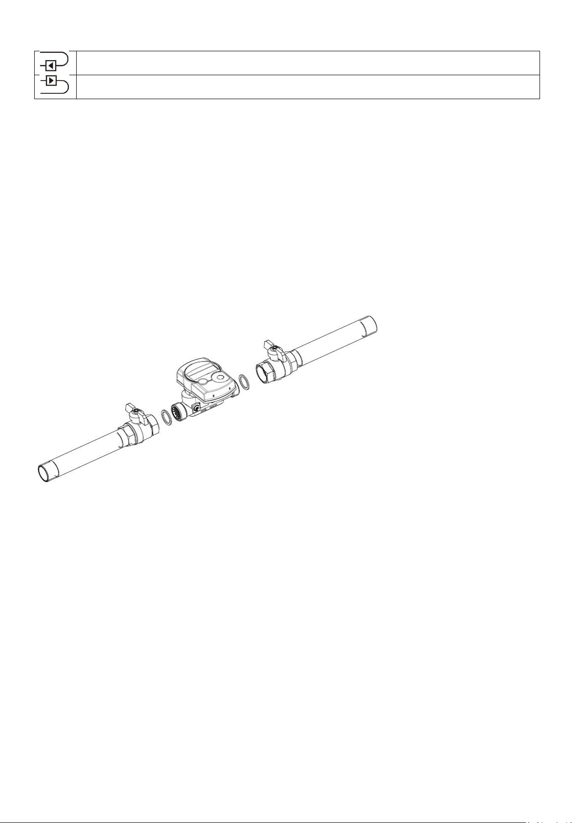
-Thermal energy meter (heat meter or combined heat/cooling meter) consisting of a detachable calculator,
a flow sensor and two temperature sensors, all permanently connected to each other.
-Installation kit
-Installation and Operating Instructions
3General Information
-Valid standards for the application of heat meters: EN 1434, parts 1 –6; the Measuring Instrument
Directive 2004/22/EC, Annexes I and MI-004; and the relevant national verification regulations.
-For the selection, installation, commissioning, monitoring and maintenance of the instrument observe the
standard EN 1434 part 6 as well as Annex 22 of the verification regulations (for Germany).
-National regulations for the consumption measurement of cooling must be observed.
-The technical regulations for electrical installations must be observed.
-This product fulfils the requirements of the European Council Directive on Electromagnetic Compatibility
(EMC Directive) 2004/108/EC.
-The identification plate of the instrument and the seals must not be removed or damaged –otherwise the
guarantee and the approved application of the instrument are no longer valid!
-To achieve measurement stability of the meter is it necessary that the water quality meet the requirements
of the AGFW-recommendation FW-510 and the document VDI (Association of German Engineers) VDI 2035.
-The heat meter left the factory in conformance with all applicable safety regulations. All maintenance and
repair work is to be carried out only by qualified and authorized technical personnel.
-The instrument must be stored and transported at temperatures above-freezing.
-Instruments with activated radio function are not allowed on air freight.
-The correct installation point in the system must be chosen: forward or return flow, as stated on the type
identification label.
-The temperature sensor cables and the cable between the calculator and flow sensor must not be kinked,
rolled up, lengthened or shortened.
-To clean the heat meter (only if necessary) use a slightly moist cloth.
-To protect against damage and dirt the heat meter should only be removed from the packaging directly
before installation.
-If more than one heat meter is installed in one unit, care must be taken to ensure that all the meters have
the same installation conditions.
-All specifications and instructions listed on the data sheet and in the Application Notes must be adhered to.
-Further information can be obtained at www.engelmann.de.
-Instruments which have been replaced or exchanged must be disposed of according to relevant
environmental regulations.
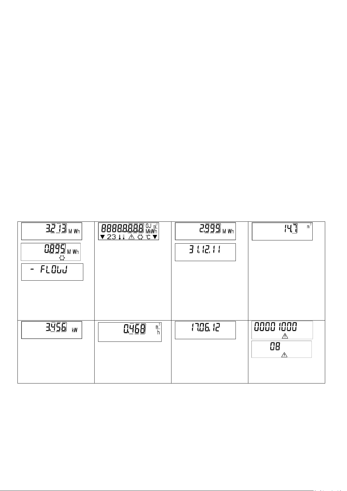
-The display is deactivated and can be activate for one minute by pushing the button (except calculator
without additional interfaces).
2015_03_03 2
3.1 Definition of pictograms on type identification label
Installation in return flow
Installation in forward flow
4Mounting the Flow Sensor
-Flush the pipes according the generally acknowledged rules of technology. Then close all the shut-off
valves. Open the nearest draining valve for pressure release.
-Drain the closed-off pipe section.
-Loosen the coupling rings and remove the old heat meter.
-Remove all old gaskets.
-Clean the sealing surfaces.
-Insert new gaskets.
-Position the flow sensor correctly, taking into account the direction of flow (arrow on the side of the flow
sensor)!
-Tighten the coupling rings.
-Detach the calculator and mount it, or rotate it to the best position for read-out.
Note
In order to simplify mounting in narrow installation spaces the calculator can be detached from the flow sensor.
To release the calculator pull it carefully up off the flow sensor.
For heat meter versions it is recommended to detach the calculator.
For heat/cooling meters the calculator must be detached from the flow sensor.
5Mounting the Temperature Sensors
For pipes of sizes < DN25 in new installations (whether new construction or refurbishment) it is required to install
the temperature sensors directly immersed in the flow (without temperature pockets).
Note
During installation of the meter make sure that the temperature sensors are mounted according to their marking.
5.1 Direct mounting (ball valve and T-piece)
-Remove the blind plug/old temperature sensor and gasket/old O-ring. Clean connection surfaces.
-Slide the O-ring off the temperature sensor and insert it to the bottom of the threaded opening of the ball
valve or the T-piece.
-Insert the temperature sensor to at least 15 mm, preferably the middle of the ball valve or T-piece (or a
little further) and screw tightly. It is important to pay attention that the tip of the temperature sensor does
not touch the bottom (the other side) of the ball valve or T-piece.
2015_03_03 3
6Start of Operation
-Slowly open the shut-off valves.
-Check that there are no leaks.
Check the following points:
-Are all shut-off valves open?
-Is the meter of the right size?
-Is the heating (heating/cooling) system clear (dirt filters not clogged)?
-Is the temperature sensor installed in the flow sensor correctly sealed to the flow sensor?
-Does the directional arrow on the flow sensor match the actual direction of flow?
-Is a flow volume displayed?
-Is a plausible temperature difference displayed?
When the meter is functioning properly, attach the seals to the temperature sensors and the flow sensor (required
to protect against manipulation).
7Display
The calculator has a liquid crystal display with 8 digits and special characters. The values that can be shown are
divided into three display loops. All data is retrieved using the push button next to the display. At the start you are
automatically in the main loop (1st level). By pressing the push-button longer than
4 seconds you change to the next display loop. Keep the push-button pressed until you reach the desired
information loop. By pressing the push-button briefly you can scan all the information within a loop. After 1 minute
of non-use of the push-button, the display automatically returns to the main loop.
Level 1/Main loop
1) Standard display: total
heat energy; alternating
display: cooling energy (for
heating/cooling meter) and
when negative flow
2) Segment test, all segments
triggered simultaneously
3) Heat energy at last reading
date alternating with last
reading date1
4) Total flow volume in m³
5) Current power in kW
6) Current flow in m³/h
7) Current date
8) Information message
(alternating binary and
hexadecimal display)
2015_03_03 4
9) Tariff register 1: values
alternating with tariff register
number and criteria2
10) Tariff register 2: values
alternating with tariff register
number and criteria2
11) Momentary reading of
the pulse counter 1
alternating with the pulse
value2
12) Momentary reading of
the pulse counter 2
alternating with the pulse
value2
Level 2/Technician’s loop
1) Maximum power in kW
2) Maximum flow in m³/h
3) Forward flow temperature
in °C
4) Return flow temperature
in °C
5) Temperature difference
6) Days in operation since
calibration
7) Sensor type/installation
point
8) M-Bus address
9) Serial number
10) Firmware version
Level 3/Statistics loop
1) Previous reading date alternating with its value.
Alternatively, the total volume or tariff values can be
displayed1.
2 -16) Monthly values: dates alternating with their values.
Alternatively, the total volume or tariff values can be
displayed1.
1 Up to the end of the month the consumption and reading date for that month will be shown as 0.
2It can be set using the software “Device Monitor”. A dedicated meter password is necessary. The password is
available from the manufacturer.
8Technical Data
Approval Data
Nominal flow qp
m³/h
0.6
1.5
2.5
3.5
3.5
6.0
6.0
Accuracy class
EN 1434-1:2007; class 2/3
Dynamic range;
Minimum flow qi/qp
1:50
1:50
1:100
1:125
1:100
1:100
1:125
1:150
1:100
1:125
1:150
1:100
1:100
Maximum flow qs/qp
2:1
Mechanical class
M1
Electromagnetic class
E1
Protection class of flow sensor
IP65
Flow disturbance class
U0
Flow Sensor
Nominal diameter DN
mm
15
15
20
20
25
25
25
2015_03_03 5
Maximum flow qs
m³/h
1.2
3.0
5.0
7.0
7.0
12.0
12.0
Pressure drop ∆p at qp
mbar
40
215
110
210
210
200
200
Nominal pressure PN
bar
16
Maximum pressure MAP
bar
16
Low flow threshold
l/h
6
6
12
14
14
30
30
Installation length
mm
110
110
130
130
150
150
260
Connection thread
inch
G3/4B
G3/4B
G1B
G1B
G1 1/4B
G1 1/4B
G1 1/4B
Temperature range
°C
15 –90
Mounting position
horizontal; vertical
Point of installation
standard
return flow (standard version)
forward flow (optional version)
Calculator
Ambient temperature
°C
5 - 55; see ‘Influencing_factors_battery_lifetime’
Temperature range
°C
0 - 105
Temperature difference
K
3 –100
Measuring cycle temperature
sec
4/60; dynamic
Measuring cycle flow
sec
2
Protection class
IP54
Power supply
3 V lithium battery
Battery lifetime, estimated
years
Standard: 10 years; 6 years + 1 with pulse output: see
“Influencing_factors_battery_lifetime”.
Data storage
E2PROM; daily
Display
8 digits + special characters
Interfaces
standard
infrared
optional
M-Bus galvanically isolated; M-Bus galvanically isolated + 2 pulse
inputs; wireless M-Bus; wireless M-Bus + 2 pulse inputs; pulse output
Temperature Sensors
Sensor type
Platinum precision resistor Pt1000
Connection type
2-wire technique
Diameter
mm
5.0; 5.2; 6
Length of cables
m
1.5; 3
Type of installation
asymmetric; symmetric
9Additional Interfaces
9.1 Optical (infrared) interface
For the communication with the optical interface an optocoupler and the Device Monitor is necessary. The
optocoupler and the‚ Device Monitor’ software are available as accessory equipment.
Baud rate: 2400 baud
The optical infrared interface is activated by pressing the push-button. If within 60 seconds neither a valid telegram
is received nor the push-button pressed again, the interface is deactivated. The number of read-outs via the optical
interface is limited to 300 times per day.
9.2 M-Bus (optional)
The M-Bus is a galvanically isolated interface for the transmission of meter data (absolute values).
2015_03_03 6
9.3 General information about the M-Bus interface
It is important to note that the acknowledged state of the art technology rules and the relevant legal restraints
(international and local; see 9.3.1 “Relevant Norms, Standards an Literature on the M-Bus”) are to be observed.
The installation has to be performed by authorized, skilled persons.
If the regulations and the information in the installation and operating instruction manuals are not strictly followed,
or if the installation is shown to be faulty, any resulting expenses will be charged to the company responsible for
the installation.
Recommended type of cable: Telephone cable J-Y(ST)Y 2x2x0.8mm².
It is important to make sure that the topology of the M-Bus network (cable lengths and cross-sections) is suitable
for the baud rate (2400 Bd) of the end instruments.
Further information can be found in the detailed ‘Application Note M-Bus’.
9.3.1 Relevant norms, standards and literature on the M-Bus
IEC 60364-4-41 (2005-12)
Low-voltage electrical installations - Part 4-41: Protection for safety -
Protection against electric shock
IEC 60364-4-44 (2007-08)
Low-voltage electrical installations - Part 4-44: Protection for safety -
Protection against voltage disturbances and electromagnetic disturbances
IEC 60364-5-51 (2005-04)
Electrical installations of buildings - Part 5-51: Selection and erection of
electrical equipment - Common rules
IEC 60364-5-54 (2011-03)
Low-voltage electrical installations - Part 5-54: Selection and erection of
electrical equipment - Earthing arrangements and protective conductors
EN 50310 (2010)
Application of equipotential bonding and earthing in buildings with
information technology equipment
EN 13757-1:2002, 2:2004, 3:2004
Communication systems for meters and remote reading of meters
The M-Bus
A Documentation, Version 4.8, M-Bus User group
TI Technical Journal
Texas Instruments Technical Journal Vol. 8, 1991 M-Bus
9.3.2 Additional technical specifications
The installation has to fulfil the requirements of the relevant norms, standards and literature (see paragraph 9.3.1)
and the specifications as follows.
Maximum voltage M-Bus
42 V
Minimum voltage M-Bus
21 V
Maximum ripple voltage
200 mV; EN 13757-2:2004; 4.3.3.6
Maximum voltage potential
differences
2 V
9.3.3 Technical data M-Bus
Primary address
0 (factory setting); 1 –250 (configurable)
Baud rate
2400; 300 (configurable)
Connecting cable length
1 m
9.3.4 Number of possible read-outs
The number of possible read-outs depends on the number of instruments in the M-Bus network.
Number of instruments in
network
Read-outs per day primary
address
Read-outs per day secondary
address (without using SND NKE)
3
655
275
20
485
170
60
300
90
120
190
52
250
105
27
If fewer read-outs are carried out, the unused “credit”is stored in the instrument and can be used later.
2015_03_03 7
During M-Bus communication with an end instrument the other interfaces (push-button, optical interface) of this
instrument cannot be used.
9.4 Radio interface wireless M-Bus EN 13757-3, EN 13757-4 (optional)
The radio interface is for the transmission of meter data (absolute values).
General information about the radio interface
Installation of radio components between or behind heating pipes, or the presence of other bulky obstacles directly
over or in front of the housing must be avoided.
The transmission quality (range, telegram processing) of radio components can be negatively influenced by
instruments or equipment with electromagnetic emissions, such as telephones (particularly LTE mobile radio
standard), Wi-Fi routers, baby monitors, remote control units, electric motors, etc.
In addition, the construction of the building has a strong influence on the transmission range and coverage.
Furthermore, when using installation boxes (substations) they must be equipped with non-metallic covers or doors.
The factory-setting of the clock in the meter is standard (winter) Central European Time (GMT +1). There is no
automatic changeover to daylight savings (summer) time.
The radio function is deactivated upon delivery (factory-setting). See section 9.4.3 “Activation of the radio
interface”.
9.4.1 Technical data radio
Frequency
868 MHz
Transmission power
up to 12 dBm
Protocol
wireless M-Bus based on EN 13757-3
Selectable modes
S1/T1/C1
Telegrams
-Short telegram in conformity to AMR (OMS-Spec_Vol2_Primary_v301): energy
(heat/cooling energy, pulse input 1, pulse input 2), total volume, flow, power,
information message, return flow temperature, temperature difference
-Long telegram for walk-by read-out: energy (heat/cooling energy, pulse input 1,
pulse input 2), total volume, information message, 15 monthly values
Encryption
AES: Advanced Encryption Standard; key length: 128 bits
9.4.2 Radio configuration*
Parameter
Possible settings
Factory settings
(Battery lifetime, estimated: 6 + 1 years)
Mode
S1/T1/C1; unidirectional
T1; unidirectional
Transmission period
00:00 –24:00; any time period in the day
7:00 am –7:00 pm
Transmission interval
120 seconds - 240 minutes
120 seconds (heat meters)
Weekdays
Monday –Sunday (any weekday)
Monday - Friday
Weeks in a month
1 –4 (4: uninterrupted, incl. a possible 5th
week)
1 –4 (4: uninterrupted, incl. a possible 5th
week)
Months
1 –12
1 –12
Radio activation date
01.01 - 31.12. (day.month)
not set
AES-128 Encryption
-Not encrypted
-Encrypted:
-Engelmann Master Key
-random key per instrument
-activated/not activated
Master Key; not activated
Type of telegram
-Short telegram AMR (OMS-
Spec_Vol2_Primary_v301)
-Long telegram walk-by
Short telegram AMR
*Factory settings may vary from the above.
2015_03_03 8
9.4.3 Activation of the radio interface
The radio interface leaves the factory deactivated. It can be activated as follows:
a. Without using additional software the radio function can be activated by pressing the push-button for over
3 seconds while at the display item ‘M-Bus address’, second level, item 8 (see section 7 Display, Level
2/Technician’s Loop). The standard factory-settings will be activated.
b. The radio function can also be activated using the software ’Device Monitor’. This software can be ordered
separately as an option. The exact procedure for activating the radio function using this software is
described in the accompanying handbook.
After successful activation of the radio function a triangle will appear permanently in the lower left corner of the
display.
If using the compact mode, for one hour after activation the meter transmits in installation mode. This means that
format telegrams and compact telegrams are sent alternately.
During installation mode at least one meter of the version being installed (forward or return flow, heat or
heat/cooling, pulse inputs, display units) must be read out with the Engelmann Read-out Software. The format of
the telegram will be stored locally in the PC in an .xml file.
After completion of the installation mode only compact telegrams will be transmitted.
9.5 Two additional pulse inputs (optional; only in conjunction with M-Bus or radio)
With this option, additional instruments with pulse outputs can be read out via M-Bus or radio.
General information about pulse inputs
It is important to note that the acknowledged state of the art technology rules and the relevant legal restraints
(international and local; see 9.5.1 “Relevant norms, standards and literature on the pulse inputs”) are to be
observed.
The installation has to be performed by authorized, skilled persons.
If the regulations and the information in the installation and operating instruction manuals are not strictly followed,
or if the installation is shown to be faulty, any resulting expenses will be charged to the company responsible for
the installation.
9.5.1 Relevant norms, standards and literature on the pulse inputs
IEC 60364-4-41 (2005-12)
Low-voltage electrical installations - Part 4-41: Protection for safety - Protection
against electric shock
IEC 60364-4-44 (2007-08)
Low-voltage electrical installations - Part 4-44: Protection for safety - Protection
against voltage disturbances and electromagnetic disturbances
IEC 60364-5-51 (2005-04)
Electrical installations of buildings - Part 5-51: Selection and erection of
electrical equipment - Common rules
IEC 60364-5-54 (2011-03)
Low-voltage electrical installations - Part 5-54: Selection and erection of
electrical equipment - Earthing arrangements and protective conductors
EN 50310 (2010)
Application of equipotential bonding and earthing in buildings with information
technology equipment
EN 1434-2:2007
Heat Meters - Part 2: Constructional requirements
9.5.2 Technical data pulse inputs
Pulse input class
CMOS; IB according to EN 1434-2:2007
Internal pull-up voltage
+ 3 V DC
Internal pull-up resistance
2 MΩ
Current
= 1.5 µA
High-level threshold
U ≥ 2 V
Low-level threshold
U ≤ 0.5 V
Length of connecting cable
1 m
2015_03_03 9
9.5.3 Electrical requirements on the pulse output of the instrument to be connected (e.g. flow meter)
Pulse output class
(passive) output OA (reed contact/electronic switch) or OC (open collector)
according to EN 1434-2:2007
Pulse length "on"
≥ 100 ms
Pulse length "off"
≥ 100 ms
Current
= 1.5 µA
Resistance "contact open"
≥ 6 MΩ
Resistance "contact closed"
≤ 3 kΩ
9.5.4 Setting up the two additional pulse inputs
The optional pulse inputs 1 + 2 for external meters can be set up using the “Device Monitor”configuration
software.
The input pulse value, the units and the starting values of the external meters can be configured.
9.5.5 Set-up possibilities
Pulse value
Units
1
litres/kWh/pulse without unit
2,5
litres/kWh/pulse without unit
10
litres/kWh/pulse without unit
25
litres/kWh/pulse without unit
100
litres/kWh/pulse without unit
250
litres/kWh/pulse without unit
1000
litres/kWh/pulse without unit
Installation notes for pulse inputs
It is important that the pulse cables not be affected by (or exposed to) the M-Bus voltage!
Check the polarity of pulse generators with ‘open collector’ outputs.
The cable wires must not touch each other during installation, otherwise pulses will be counted in the instrument.
When setting up the meter it may be necessary to adjust the meter reading of the instruments connected and the
pulse value using the Device Monitor software.
9.5.6 Pin assignments 6-wire cable (only in conjunction with M-Bus)
Pin
Colour
Connection
1
White
IE1+
2
Brown
IE1┴
3
Green
IE2┴
4
Yellow
IE2+
5
Grey
M-Bus
6
Pink
M-Bus
9.5.7 Pin assignments 4-wire cable (only in conjunction with radio)
Pin
Colour
Connection
1
Yellow
IE1+
2
Green
IE1┴
3
Brown
IE2┴
4
White
IE2+
9.6 Potential-free pulse output (optional)
The potential-free pulse output is an electronic switch that outputs counting pulses of the meter which can be used
for any purpose.
The pulse output closes, corresponding to the pulse value shown on the type identification label on the instrument.
2015_03_03 10
9.6.1 Technical data pulse output
Pulse output class
OA (electronic switch) according to EN 1434-2:2007
Pulse value heat energy
1 kWh/pulse
Pulse value volume (optional)
100 l/pulse
Peak switching current
300 mA ~/-
Switching voltage, maximum
35 V ~/-
Switching power, maximum
300 mW
Contact isolation
> 109Ohm
Contact resistance (on)
max. 25 Ohm
Contact capacity
1.5 pF
Maximum current
120 mA
Withstand voltage (open contact)
350 V ~/-
Closure time
125 ms
Interval between pulses
125 ms
10 Information Messages
When the instrument has detected an information message, the message symbol is displayed:
The specific message can be found at the menu item 8 ‘Information message’ in Level 1/Main loop (see section 7
“Display”). The instrument recognizes eight message causes, which can also occur in combination with each other.
The messages are shown on the display. The message code is displayed alternately in binary and hexadecimal form.
Binary display
Description
Hexadecimal display
1 at first place
Low battery
H 80
1 at second place
Check sum error
H 40
1 at third place
E2PROM defective
H 20
1 at fourth place
Instrument has been reset
H 10
1 at fifth place
Time-out TDC (Time-to-digital
converter)
H 08
1 at sixth place
Internal calibration defective
H 04
1 at seventh place
Return flow sensor defective
H 02
1 at eighth place
Forward flow sensor defective
H 01
Example: Time-out TDC (Time-to-digital converter)
Message
Low battery
Check sum error
E²PROM fault
Reset
Time-out TDC
Internal calibration
error
Return flow sensor
fault
Forward flow
sensor fault
Alternating hexadecimal
message displayed (LCD)
Bit
7
6
5
4
3
2
1
0
Display location
1
2
3
4
5
6
7
8
Alternating binary
message displayed (LCD)
When a message appears in the standard display (total heat, or alternating total heat and cooling energy), with the
exception of the messages ‘Reset’ (10) and ‘Time-out TDC’ (08) in the case of air in the measuring tube, the
instrument must be exchanged and sent to the supplier for examination.
2015_03_03 11
10.1 Message description
Message
Effect
Possible cause
Low battery
No influence to the calculation
Adverse environmental conditions;
Long operating time
Check sum error
No calculations are carried out. The
registers of flow and energy are not
being updated.
Defective component.
E2PROM fault
After a reset, the instrument is
without function.
Defective component.
Reset
The measurements since the last
storage of data in the E2PROM are
lost (max. one day)
EMC
Time-out TDC;
no measurement of volume
No calculations are carried out. The
registers for volume and energy are
not being updated (no new data is
being stored).
Air in the system; Volume scanning
defective; Connecting cable between
the calculator housing and the flow
sensor damaged.
Internal calibration error
There is no energy calculation. The
registers for flow and energy are
not being updated (no new data is
being stored).
A defect on the calculator circuit
board.
Rf-sensor fault
No calculations are carried out. The
registers for flow and energy are
not being updated (no new data is
being stored).
Sensor cable severed; sensor cable
shorted circuited t.
Ff-sensor fault
No calculations are carried out. The
registers for flow and energy are
not being updated (no new data is
being stored).
Sensor cable severed; sensor cable
shorted circuited.
11 Mounting with Wall Support
For mounting the calculator on the wall, a sticker pad and a wall mounting support are available. They must be
ordered separately. The adhesive surfaces must be clean and free of grease.
12 MID Declaration of Conformity
For the product described in this document we confirm, as the manufacturer, that it meets the fundamental
requirements of the following directives:
-Directive 2004/22/EC of 31 March 2004 on measuring instruments, in particular those in Annex MI-004
-Directive 2004/108/EC on EMC
-Directive 2006/95/EC on low voltage
-Directive 1999/5/EC (R&TTE)
The complete signed declaration can be found at www.engelmann.de.
2015_03_03 12
13 Manufacturer
Engelmann Sensor GmbH
Rudolf-Diesel-Str. 24-28
69168 Wiesloch-Baiertal
Germany
Tel: +49 (0)6222-9800-0
Fax: +49 (0)6222-9800-50
E-Mail: [email protected]
www.engelmann.de
14 Contact
Maddalena S.p.A.
Via G.B. Maddalena, 2/4
33040 Povoletto (UD) –Italy
Tel.: +39.0432.634811
Fax.: +39.0432.679820
www.maddalena.it
Subject to technical change

Other manuals for microCLIMA U

1

This manual suits for next models

1

Other MADDALENA Measuring Instrument manuals

MADDALENA microCLIMA ULTRA User manual

MADDALENA

MADDALENA microCLIMA ULTRA User manual

MADDALENA ArrowEVO Parts list manual

MADDALENA

MADDALENA ArrowEVO Parts list manual

MADDALENA microCLIMA/SENSOSTAR 2+ MSH User manual

MADDALENA

MADDALENA microCLIMA/SENSOSTAR 2+ MSH User manual

MADDALENA ElecTo Bulk Parts list manual

MADDALENA

MADDALENA ElecTo Bulk Parts list manual

MADDALENA ElecTo SONIC Parts list manual

MADDALENA

MADDALENA ElecTo SONIC Parts list manual

MADDALENA ElecTo Bulk User manual

MADDALENA

MADDALENA ElecTo Bulk User manual

MADDALENA ElecTo SJ Parts list manual

MADDALENA

MADDALENA ElecTo SJ Parts list manual

MADDALENA ElecTo SJ Parts list manual

MADDALENA

MADDALENA ElecTo SJ Parts list manual

MADDALENA QuadraPlus User manual

MADDALENA

MADDALENA QuadraPlus User manual

MADDALENA microCLIMA User manual

MADDALENA

MADDALENA microCLIMA User manual

MADDALENA SensoStar C User manual

MADDALENA

MADDALENA SensoStar C User manual

MADDALENA microCLIMA U User manual

MADDALENA

MADDALENA microCLIMA U User manual

MADDALENA SJ PLUS User manual

MADDALENA

MADDALENA SJ PLUS User manual

MADDALENA Arrow Mobile Android User manual

MADDALENA

MADDALENA Arrow Mobile Android User manual

MADDALENA E-Bulk Parts list manual

MADDALENA

MADDALENA E-Bulk Parts list manual

MADDALENA ElecTo SJ Parts list manual

MADDALENA

MADDALENA ElecTo SJ Parts list manual

Popular Measuring Instrument manuals by other brands

Agilent Technologies FRG-700 Short operating instructions

Agilent Technologies

Agilent Technologies FRG-700 Short operating instructions

Chauvin Arnoux PAC 22 user manual

Chauvin Arnoux

Chauvin Arnoux PAC 22 user manual

Martini Instruments MI 306 instruction manual

Martini Instruments

Martini Instruments MI 306 instruction manual

Labgear 630RS quick start guide

Labgear

Labgear 630RS quick start guide

Envionic FA845 user manual

Envionic

Envionic FA845 user manual

Kestrel 1000 instruction manual

Kestrel

Kestrel 1000 instruction manual

ABB AC211 installation guide

ABB

ABB AC211 installation guide

MFJ MFJ-852 instruction manual

MFJ

MFJ MFJ-852 instruction manual

Electrex ATTO D4 DC installation instructions

Electrex

Electrex ATTO D4 DC installation instructions

Siemens Sitrans F Series operating instructions

Siemens

Siemens Sitrans F Series operating instructions

Surecom SF-103 user manual

Surecom

Surecom SF-103 user manual

Tesco DTS-2990 Operation manual

Tesco

Tesco DTS-2990 Operation manual

AquaChek TruTest user manual

AquaChek

AquaChek TruTest user manual

LG 2WM-LG installation instructions

LG

LG 2WM-LG installation instructions

Twilight MP-2000 Operation manual

Twilight

Twilight MP-2000 Operation manual

EPI Valumass 400 Series Installation, wiring & configuration

EPI

EPI Valumass 400 Series Installation, wiring & configuration

Microcare Web-Logger user manual

Microcare

Microcare Web-Logger user manual

ANALOX ATA Pro Technical manual

ANALOX

ANALOX ATA Pro Technical manual

manuals.online logo
manuals.online logoBrands
  • About & Mission
  • Contact us
  • Privacy Policy
  • Terms and Conditions

Copyright 2025 Manuals.Online. All Rights Reserved.