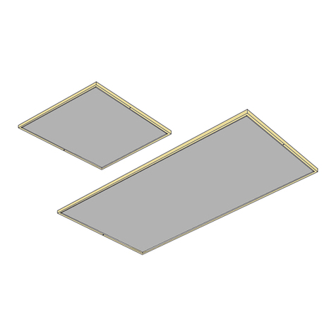
Suntherm AL LED 150 User manual

INFRAROT HEIZPANEEL
INFRARED HEATING PANEL
SUNTHERM LED
BEDIENUNGSANLEITUNG
seite 2-6
INSTRUCTION MANUAL
page 7-11

2
•Montagen und jegliche Eingriffe in das Heizpaneel dürfen ausschließlich von einer fachkundigen Person
durchgeführt werden. Vor dem Eingriff oder der Handhabung muss das Heizpaneel vom Netz getrennt werden.
Beim Transport des Heizpaneels, der Handhabung und Montage ist Vorsicht geboten, da es sich um ein
zerbrechliches Material handelt.
•Dieses Gerät darf von Kindern ab 8 Jahren sowie von Personen mit eingeschränkten physischen, sensorischen
oder geistigen Fähigkeiten oder mangelnder Erfahrung und Kenntnissen nur dann verwendet werden, wenn
sie beaufsichtigt oder über die sichere Benutzung des Geräts aufgeklärt werden und die möglichen Gefahren
verstehen. Kinder dürfen nicht mit dem Gerät spielen. Die durch den Benutzer durchzuführende Reinigung und
Wartung dürfen nicht unbeaufsichtigte Kinder durchführen.
•Falls die Versorgungsleitung beschädigt ist, muss sie vom Hersteller, seinem Servicetechniker oder einer
entsprechend qualifizierten Person ausgetauscht werden, um eine Gefahr zu vermeiden.
•Das Heizpaneel ist für die Installation in einer Höhe von mindestens 1,8m über dem Boden bestimmt.
•Einige Teile dieses Produkts können sehr heiß werden und Verbrennungen verursachen.
•Dieses Gerät ist mit keiner Raumtemperaturregelung ausgestattet. Verwenden Sie dieses Heizpaneel nicht in
kleinen Räumen, wenn sich darin Personen befinden, die diesen Raum nicht mit eigenen Kräften verlassen können,
es sei denn, eine dauerhafte Aufsicht ist gewährleistet.
•Der Hersteller empfiehlt den Anschluss an die Raumtemperaturregelung.
•Während der Handhabung des Heizpaneels empfiehlt der Hersteller die Verwendung von Handschuhen, um eine
Verschmutzung des Rahmens und der vorderen Strahlungsfläche des Heizpaneels zu vermeiden.
•Achten Sie auf die Wahl des Verankerungsmaterials (Dübel) in Bezug auf die Deckenkonstruktion. Wenden Sie sich
ggf. an den Lieferanten des Verankerungsmaterials.
HINWEIS
!!
DE

3
Das Heizpaneel SUNTHERM LED ist zur Beleuchtung und zum Beheizen oder Temperieren von Wohn-, Gewerbe-
oder Industrieräumen bestimmt. Das Heizpaneel besteht aus einer Heizplatte und einem Rahmen mit einem LED
Lichtstreifen. Die Vorderseite des Heizpaneels ist mit einer Beschichtung versehen. Die Oberfläche des Heizpaneels
ist je nach Paneelart glatt oder sandgestrahlt. Das Produkt wird in verschiedenen Abmessungen und Leistungen
geliefert (siehe die Tabelle unten). Es handelt sich um ein Gerät der I. Schutzklasse IP44 je nach Paneeltyp (auf der
Rückseite des Paneels angeführt). Sowohl das Heizpaneel als auch die Leuchte werden mit 230 V/50 Hz betrieben.
Das Produkt wird mit Befestigungselementen zur Anbringung an der Wand geliefert. Wir empfehlen, dass jeweils
zwei Personen die Installation durchführen. Bei der Installation muss das Netzkabel vom Netz getrennt sein, gemäß
Kapitel Montage. Das Heizpaneel kann auf Materialien der Baustoffklassen A1, A2, B, C, D montiert werden. Die
Abmessungen der einzelnen Modelle sind in der folgenden Tabelle angeführt.
PRODUKTBESCHREIBUNG
i
iDE
A
X
B
Y
C
TYPE HEIZLEISTUNG
(W)
LICHTLEISTUNG
(W)
LICHTSTROM
(lm)
A
(mm)
B
(mm)
C
(mm)
X
(mm)
Y
(mm)
AL LED 150 150 60 3260 835 255 37 568 115
AL LED 200 200 52 3300 535 535 37 277 382
AL LED 200dl 200 69 3560 835 385 37 573 241
AL LED 250 250 70 3700 1035 285 37 716 134
AL LED 300 300 69 3680 635 635 37 371 482
AL LED 400 400 76 4050 885 535 37 618 382
AL LED 500 500 75 4930 975 635 37 716 482
AL LED 500dl 500 84 4530 1035 535 37 716 382
AL LED 600 600 94 5010 1235 535 37 972 382
AL LED 700 700 89 5640 1235 635 37 972 482

4
Die Installation, der elektrische Anschluss und die Erstinbetriebnahme
dürfen nur von einer entsprechend qualifizierten Person durchgeführt
werden. Die Heizpaneele sind zur Befestigung an der Decke bestimmt,
mindestens 1,8 m über dem Boden, in einer Mindestentfernung
von 0,2 m von einer vertikalen Konstruktion. Unter dem Heizpaneel
muss ein Freiraum von mindestens 0,5 m von den vertikalen Achsen
der Heizpaneelkanten vorhanden sein, um eine freie Luftzirkulation zu
gewährleisten und eine Überhitzung zu vermeiden.
Im Badezimmer kann ein Heizpaneel mit Schutzklasse IP44 gemäß IEC
60364-7-701 installiert werden, wie rechts abgebildet. Die Installation
der Heizungsanlage im Badezimmer muss sicherstellen, dass die Person
in der Badewanne oder Dusche die Schalter und andere Steuergeräte nicht
berühren kann.
Das Heizpaneel verfügt über separate Anschlüsse für das Heizelement und für die Beleuchtung. Der feste Anschluss
am Heizpaneel muss über die Möglichkeit verfügen, das Gerät vom Netz zu trennen, wobei Kontakte in allen Polen
unterbrochen werden und das Gerät vollständig vom Netz getrennt wird.
Die Versorgungsleitung muss über die Möglichkeit verfügen, das Gerät vom Netz zu trennen, wobei die Entfernung
der durchgetrennten Kontakte bei allen Polen mindestens 3,5 mm betragen muss.
Die Stromversorgung für das Heizelement ist weiß,
die Stromversorgung für die Leuchte ist schwarz.
Farbige Kennzeichnung der Leiter:
•Braun – L – Phase
•Blau – N – Neutralleiter
•Gelb – PE – Schutzleiter
Das Paneel darf nicht unmittelbar über einer Steckdose angebracht werden.
Bei einer Beschädigung des Versorgungskabels muss das Heizpaneel außer Betrieb gesetzt werden.
Das Heizpaneel muss regelmäßig mit einem feuchten Tuch ohne Zugabe von Reinigungs- und Lösungsmitteln oder
mit dem Staubsauger vom Staub befreit werden. Das Gerät muss vor Beginn jeder Heizperiode entstaubt werden.
Während der Wartungsarbeiten muss das Heizpaneel vom Stromnetz getrennt und kalt sein.
Bei der ersten Inbetriebnahme bzw. zu Beginn einer neuen Heizperiode muss das Heizpaneel langsam erwärmt
werden und im beheizten Raum muss ausreichend gelüftet werden.
Abhängig von der Umgebung im beheizten Raum kann sich der Farbton der Strahlungsfläche des Heizpaneels
verändern.
Sämtliche Reparaturen dürfen nur vom Hersteller vorgenommen werden.
Für die Funktion des Heizpaneels gilt eine 15-jährige Garantie ab dem Verkaufsdatum. Für die Funktion der
Lichtanlage gilt eine 2-jährige Garantie ab dem Verkaufsdatum. Die Garantie bezieht sich nicht auf Schäden, die
beim Transport, durch falsche Lagerung, eine nicht fachkundige Montage oder durch Eingriffe in die Konstruktion
des Produkts entstanden sind. Die Garantie gilt nicht für den üblichen Verschleiß des Heizpaneels und teilweise Far-
bänderungen der Strahlungsfläche des Heizpaneels. Der Beleg über den Kauf des Produkts dient als Garantieschein.
STROMANSCHLUSS
GARANTIE
WARTUNG UND BETRIEB
ANBRINGUNG
225 mm
60 mm
60 mm
60 mm
DE
DE
DE
DE
L
N
PE
L
N
PE

5
1. Bauen Sie den Hängerahmen vom Heizpaneel ab,
indem Sie die beiden Federn lösen.
6. Drücken Sie das Heizpaneel in die Federn (das Paneel
muss hörbar einrasten).
5. Hängen Sie das Heizpaneel am Schlitz an die beiden
Haken am Hängerahmen auf. Vergewissern Sie sich, dass der
Stromanschluss getrennt wurde und schließen Sie die beiden
Anschlusskabel über die Anschlussleiste ans Stromnetz an.
4. Bringen Sie den Rahmen an und befestigen Sie ihn
mit den beiliegenden Schrauben.
2. Bringen Sie den Hängerahmen an der Position an,
wo sich das Heizpaneel befinden soll, und markieren
Sie mit einem Bleistift die Stellen, an denen der
Rahmen befestigt werden soll.
3. Bohren Sie die markierten Löcher mit dem
erforderlichen Durchmesser und legen Sie die
beiliegenden Dübel ein.
MONTAGE
DE

6
1. Unterbrechen Sie mit dem einschlägigen
Schutzschalter die Stromversorgung.
6. Bauen Sie den Hängerahmen ab, indem Sie vier
Schrauben lösen.
5. Entnehmen Sie das Paneel aus den Scharnieren des
Hängerahmens.
4. Lassen Sie das Paneel an den Scharnieren des
Hängerahmens hängen. Trennen Sie die beiden
Anschlusskabel von der Anschlussleiste.
2. Drücken Sie das Heizpaneel leicht in Richtung Decke
und lösen Sie mit einem flachen Schraubenzieher
oder einer Zwickzange die Feder im Schlitz des
Hängerahmens an deren Griff.
3. Gehen Sie bei der zweiten Feder genauso vor und
klappen Sie anschließend das Heizpaneel ab.
DEMONTAGE
DE
230 V

7
CAUTION
!!
•Assembly of and manipulation related to the heating panel must be carried out by qualified person. The heating
panel must be disconnected from the power source prior to work or manipulation with it. Care must be taken during
transport, manipulation and assembly of the heating panel as the material of the product is fragile.
•This appliance may be used by children age 8 and up or people with impaired physical, sensory or mental abilities
or insufficient experience and knowledge only under supervision or if they have been instructed how to use the
appliance safely and they understand the potential risks associated with its use. Children must not play with the
appliance. Cleaning and maintenance carried out by the user must not be undertaken by unsupervised children.
•If the power connection is damaged, it must be replaced by the manufacturer, the manufacturer’s service technician
or a similarly qualified individual to prevent any risks.
•The heating panel is designed to be installed at a height of at least 1.8 m above floor level.
•Some parts of this product may be very hot and cause burns.
•This appliance is not equipped with a room temperature control device. Do not use this heating panel in a small
room if there are individuals present who are unable to evacuate the room by themselves and there is no constant
supervision.
•The manufacturer recommends connecting the appliance to a room temperature control device.
•The manufacturer recommends using gloves when working with the heating panel to prevent contamination of the
frame and front radiant areas of the heating panel.
•Please select the anchoring material (wall plugs) carefully in regard to the structure of your ceiling. If necessary, ask
your supplier for advice regarding appropriate anchoring material.

8
The heating panels are designed to light and heat or maintain the desired temperature in residential, commercial or
industrial areas. The panel consists of a heating panel and a frame with LED light strip. The front side of the heating
panel has been treated with a surface coating, smooth or sandblasted depending on the type of panel. Panels are
produced in different sizes, powers and light colour temperatures (see table below).
It is a Class I appliance with IP 44 protection. Both heating element and light are powered with 230V/50Hz.
The product comes with fastening elements to enable it to be mounted to a wall. We recommend carrying out the
installation in a team of two people. The installation must be carried out with the connection cables disconnected
from the power source, as described in the Assembly chapter. The heating panel may be installed on surfaces with a
Class A1, A2, B, C or D fire resistance rating. The dimensions of the models are listed in the table below.
PRODUCT DESCRIPTION
i
i
A
X
B
Y
C
TYPE HEAT. ELEMENT
POWER (W)
LIGHT
POWER (W)
LUMINOUS
FLUX (lm)
A
(mm)
B
(mm)
C
(mm)
X
(mm)
Y
(mm)
AL LED 150 150 60 3260 835 255 37 568 115
AL LED 200 200 52 3300 535 535 37 277 382
AL LED 200dl 200 69 3560 835 385 37 573 241
AL LED 250 250 70 3700 1035 285 37 716 134
AL LED 300 300 69 3680 635 635 37 371 482
AL LED 400 400 76 4050 885 535 37 618 382
AL LED 500 500 75 4930 975 635 37 716 482
AL LED 500dl 500 84 4530 1035 535 37 716 382
AL LED 600 600 94 5010 1235 535 37 972 382
AL LED 700 700 89 5640 1235 635 37 972 482

9
The panel has separate inlets for the heating and the light. The both fixed connections of the heating panel must
contain an element allowing its disconnection from the power mains, able to fully and completely disconnect
contacts at all poles.
The power connection must be equipped with a device enabling disconnection from the power source, where the
distance of disconnected contacts is no less than 3.5 mm at all poles.
The power supply for the heating element is white.
The power supply for the light is black.
Colour coding of conductor wires:
•Brown wire – L – phase
•Blue wire – N – neutral
•Yellow wire – PE – ground
The panel must not be placed immediately above an electrical outlet. If the power connection cable is damaged,the
heating panel must be put out of operation.
The panel has a 10-year functional warranty from the date of sale. The 2 year warranty applies to the functionality
of the light. The warranty does not apply to defects caused by transport, inappropriate storage, unauthorized
installation or any interference to the product structure. The warranty also does not cover usual wear and tear of
the panel or partial changes to the colour of the panel radiant surface. The purchase receipt serves as the warranty
certificate.
ELECTRICAL INSTALLATION
WARRANTY CONDITIONS
OPERATION AND MAINTENANCE
PLACEMENT
225 mm
60 mm
60 mm
60 mm
Installation, power connection and first operation of the
appliance must be carried out by an individual with the
requisite qualifications. These heating panels are designed to
be mounted onto ceilings at a height of at least 1.8 m above
floor level and at a distance of at least 0.2 m from vertical
structures. There must be at least 0.5 m of unobstructed air
space under the heating panel measured from the vertical axes
of the edges of the heating panel to ensure free circulation of
air and to prevent overheating of the unit.
When installing the heating system in a bathroom, make sure
that a person in the bathtub or shower will not be able to touch
the switches or other control elements of the appliance.
Remove dust from the heating panel surface regularly by wiping with a damp cloth without any detergent or solving
agent, or with a vacuum cleaner. Dust must always be removed prior to starting the heating season. The heating
panel must be cold and disconnected from the power source during maintenance.
During the first operation of the heating panel or the first operation in a given heating season, heat the panel
gradually and make sure the heated room is well aired.
Depending on the environment in the heated premises, the colour shade of the panel radiant surface may change.
All repairs must be carried out solely by the manufacturer.
L
N
PE
L
N
PE
The panel has a 15-year functional warranty from the date of sale. The 2 year warranty applies to the functionality
of the light. The warranty does not apply to defects caused by transport, inappropriate storage, unauthorized
installation or any interference to the product structure. The warranty also does not cover usual wear and tear of
the panel or partial changes to the colour of the panel radiant surface. The purchase receipt serves as the warranty
certificate.

10
MOUNTING
1. Dismantle the mounting frame from the heating
panel by releasing the two spring clips.
6. Push the heating panel onto the frame until you hear
an audible click from the spring clips.
5. Hinge the heating panel recess onto two clips of the
mounting frame. Make sure that the power is switched off;
then connect both light (black cable) and heating (white cable)
of the panel to the power mains using a terminal block.
4. Mount the frame by screwing it into the ceiling with
the enclosed screws.
2. Place the mounting frame onto the intended location
of the heating panel and mark the frame anchoring
points with a pencil.
3. Drill holes of adequate diameter in the marked
anchoring points and insert the appropriate anchoring
material (wall plugs).

11
DISMOUNTING
1. Disconnect the appliance from the power by
switching off the circuit breaker.
6. Dismount the mounting frame by unscrewing the
four screws.
5. Hinge the panel out of the mounting frame.
2. Push the heating panel gently towards the ceiling
and release the spring clip ridge from the recess of the
panel using a flat tip screwdriver or forceps.
3. Repeat the procedure with the second spring clip
and then swing the heating panel down.
4. Leave the panel suspended in the mounting frame
hinges. Disconnect the connecting cables from the
terminal block.
230 V
This manual suits for next models
9
Table of contents
Languages:
Other Suntherm Heater manuals
Popular Heater manuals by other brands

Pakole
Pakole ZENIT 80+ Series Instructions for installation and servicing

Gude
Gude GGH 35 TRI manual

Blyss
Blyss Thorpe 3663602847595 quick start guide

ClimateRight
ClimateRight ClimateSAFE CRPH300 owner's manual

KING
KING KBP2406 Installaltion & maintenance manual

Truma
Truma Combi D 6 AU operating instructions

Marta
Marta MT-IH2586A user manual

CEH
CEH ODH-3000 installation instructions

Stavoklima
Stavoklima Li0 light IR 100 user manual

COLORATO
COLORATO CLHR-0015FC instruction manual

LUCHT LHZ
LUCHT LHZ Technotherm TTS 200 Assembly and operating instructions

GDC
GDC Comfortstat 2 F 8ST Installation and owner's manual