Suntor ST5815E-BPS User manual

1st
ST5815E-BPS Wireless Bridge
User Manual
1. Quick Installation & Commissioning...................................................................................................................................2nd
1.1. Preparation work for Equipment commissioning......................................................................................................2nd
1.1.1. Tools for Commissioning.................................................................................................................................2nd
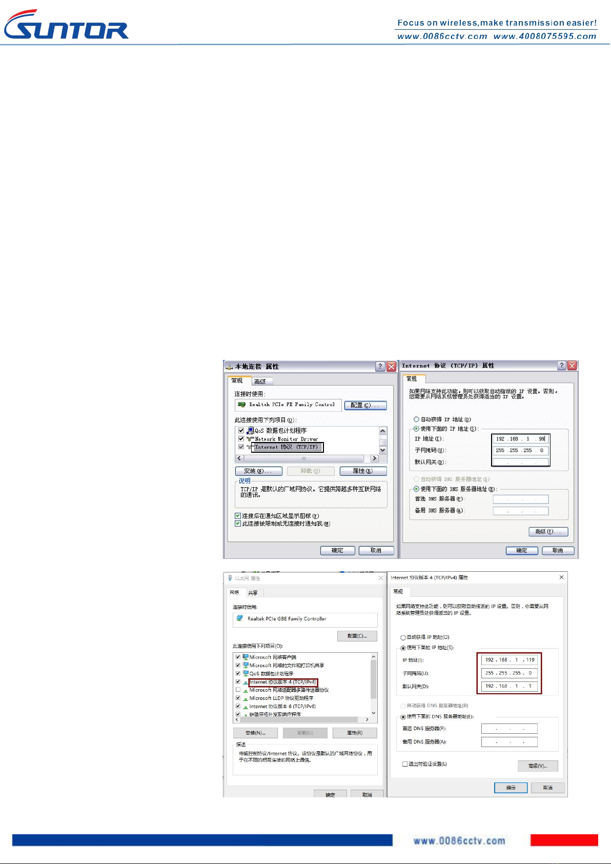
1.1.2. Modify your PC IP address..............................................................................................................................2nd
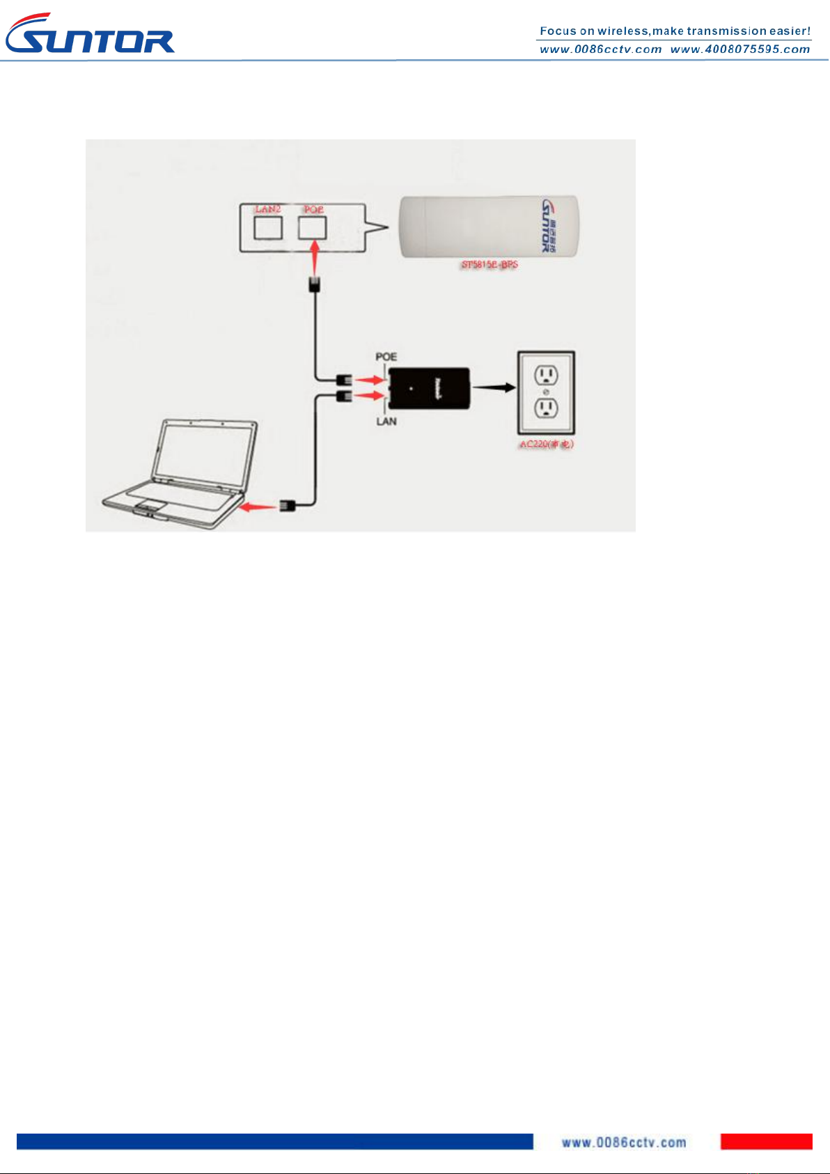
1.1.3. Connection.......................................................................................................................................................3rd
1.2. Steps for Equipment commissioning..................................................................................................................................3rd
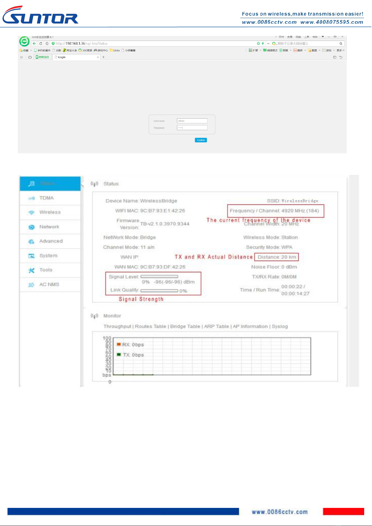
1.2.1. Login by WEB page..........................................................................................................................................3rd
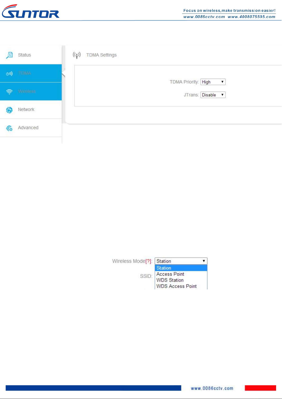
1.2.2. TDMA Settings................................................................................................................................................. 4th
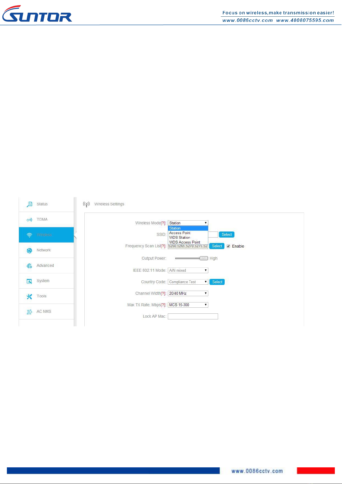
1.2.3. Wireless Settings............................................................................................................................................. 5th
1.2.4. Output Power.................................................................................................................................................. 5th
1.2.5. 802.11 mode....................................................................................................................................................5th
1.2.6. Country Code...................................................................................................................................................6th
1.2.7. Channel Width.................................................................................................................................................6th
1.2.8. Network settings..............................................................................................................................................6th
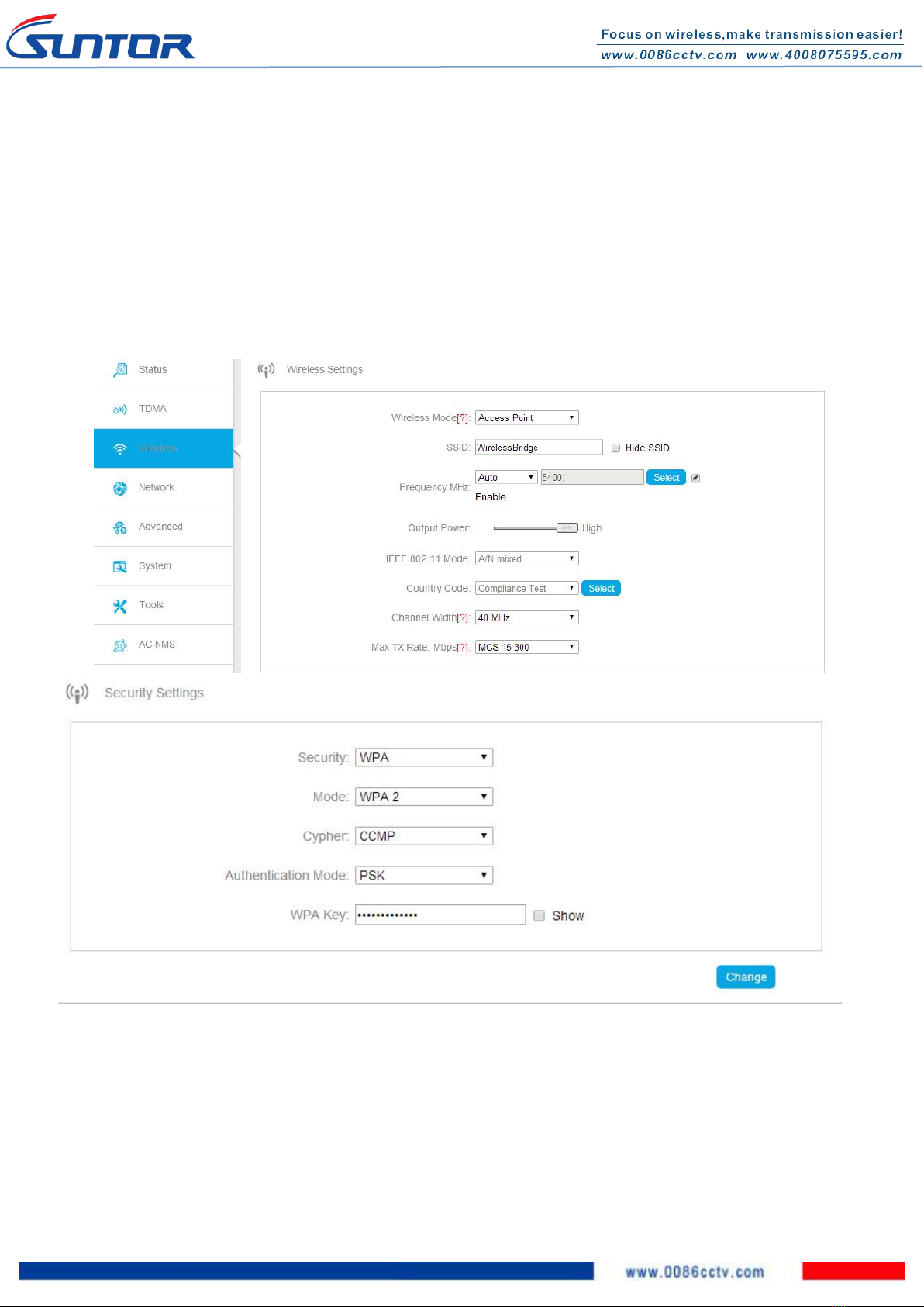
1.2.9. Wireless Network settings...............................................................................................................................7th
1.2.9.1.“AP” mode......................................................................................................................................................8th
1.2.9.2. “Station” Mode.............................................................................................................................................8th
1.2.9.3. Fill in the actual application distance parameter.........................................................................................9th
1.2.10. Signal Strength LED Settings........................................................................................................................10th
1.2.11. Communication Status Checking.................................................................................................................10th
2. Installation Precautions....................................................................................................................................................... 11th
3. Common troubleshooting methods.................................................................................................................................... 13th
4. Application Diagram............................................................................................................................................................ 13th
SUNTOR ELETRONICS CO., LIMITE

2nd
1. Quick Installation & Commissioning
1.1. Preparation work for Equipment commissioning
1.1.1. Tools for Commissioning
1*PC, 4* RJ45 Cable, ST5815E-BPS(TX), ST5815E-BPS(RX), 2*POE Adapter
1.1.2. Modify your PC IP address with same network segment as ST5815E-BPS.
ST5815E-BPS Defaults:
IPv4: 192.168.1.36
Subnet Mask: 255.255.255.0
Modifying your PC IP : 192.168.1.X(X=2~253)
Subnet Mask: 255.255.255.0
Default Gateway: 192.168.1.1
Take Window7 and Window10 as
samples:
Window7
Window10

3rd
1.1.3. Connection
Note: Please not connect PC with POE port of POE adapter. Or the PC will be burnout.
We advise using the POE supply power to ST5815E-BPS firstly. After all the LED indicators light then
connecting the PC.
1.2. Steps for Equipment commissioning
1.2.1. Login by WEB page
Note: ST5815E-BPS default IP: 192.168.1.36 User Name: admin Password: admin
Input the device IP into the browser address bar. Input the user name and Password to login.

4th
1.2.2. TDMA Settings
TDMA settings are for the developers. Keep the defaults and no need to modify it.

5th
1.2.3. Wireless Settings
ST5815E-BPS support 4 working modes: Access Point / Station / WDS Access Point / WDS Station
When using PTMP transmission, make alls the transmitters using Station mode and the recevier using AP mode. The same
with WDS.
When using PTP transmission, if one device using Station mode, the other one need to use AP mode.
Note: The operation interface of Station and AP are different. In AP mode, the device support manually or automatically
set the frequency. In Station mode, the device can using “Frequency Scan List” to scan the nearby frequency so that the
device can avoid the frequency
interference.
1.2.4. Output Power
The device default is using max power. However ssers can adjust the outpower according to the signal strength or ditance.
1.2.5. 802.11 mode

6th
Choosing the default mode(only one option)
1.2.6. Country Code
The transmitter and receiver can choose the test mode. Both of them can also choose the same country,
such as China.
1.2.7. Channel Width
20/40Mhz: For short distance but high transmission rate
5/10Mhz: For long distance but low transmission rate
1.2.8. Network settings
The factory default IP address is 192.168.1.36, Users can change the IP address. As shown below:

7th
After the IP modification is completed, select"apply" and then automatically jump to the login page. Using
the user name and password to re-enter the operation interface to continue the configuration.
1.2.9. Wireless Network settings
ST5815E-BPS support 4 working modes: Access Point / Station / WDS Access Point / WDS Station
AP mode communicate with Station mode. WDS AP mode communicate with WDS Station mode. Now we
take "AP" and "Station" mode as a sample to do the settings.

8th
1.2.9.1.“AP” mode
If the communication mode is PTP, there are two devices A and B. If A device use Ap mode, so B device
need to use Station mode.
Open A device Wireless operation interface, to set the “wireless mode”, “SSID”, “Frequency”, “Channel
Width”, “Output Power” and “Security Settings”. Then save the settings.
1.2.9.2. “Station” Mode
Open B device Wireless operation interface and choose Station mode. Then set the parameters of “SSID”,
“Frequency”, “Channel Width”, “Output Power” and “Security Settings”. Then save the settings.

9th
1.2.9.3. Fill in the actual application distance parameter

10th
After complete the settings, save it. Then all the Wireless Network settings are finished.
1.2.10. Signal Strength LED Settings
Open "High class Settings-LED Configuration", when the signal strength reach the following value, the
corresponding signal indicator will light.This allows the technician can easily operate and adjust the
direction of CPE during installation.
1.2.11. Communication Status Checking
When the all the devices are in normal communication status, users can using PC to login the device status
interface to check the communication quality. So that users can adjust the CPE direction according to the
quality.
AP mode Status

11th
Station Mode Status:
2. Installation Precautions
This wireless device allows users to access the network wirelessly anywhere in its effective range. However,
please note that the number, thickness and location of buildings, trees, walls, ceilings, or other objects

12th
within the scope of the wireless signal can limit the signal to a certain extent, get out or refraction. The
distance after the penetration depends on the material in which you place the obstruction, as well as the
surrounding electromagnetic environment and the frequency of the device itself. To maximize the wireless
signal transmission distance,please follow the following basic principles:
Keep the device away from electrical equipments or electrical devices which generate RF interference
signals(1-2meters)
Make ditance from TX and RX are line of sight
Solid metal doors or reinforced concrete walls have a great impact on signal transmission, so wireless
devices should avoid these materials.
As far as possible to increase the height of the TX and RX, but pay attention to the equipment of mine
(lightning protection equipment must be effectively grounded)
Try to choose pure copper cable, because the quality of the cable can directly affect the signal
transmission quality. The length of cable connect with outport is generally no more than 20 meters.
The length of the cable connected to the LAN port is generally no more than 100 meters.
Please pay attention to POE power supply voltage instructions.
The installation of the wireless device need to follow the rationale (Regard the wireless device
radiation beam as the flashlight irradiation beam. The two flashlight irradiation beam on the overlap
together is the best status. So two equipments are face to face is the best Angle) if use high and low
gap in the environment, users can flexible adjust the antenna pitch angle. (The following diagram)
If many device are installed in same place, each device need to separated by a certain distance to avoid
interference.
Wrong Installation Type
Right Installation Type

13th
3. Common troubleshooting methods
Troubles 1: There is no image in the process suddenly, follow the next recommendations to troubleshoot.
Hardware malfunction
First to check and confirm if the power supply is normal. This point can be made clear from the POE power
adapter or power LED on device. Then check and confirm if the network cable and connectors are damaged
or aging. If yes, replace the cable and connectors.
Device Malfunction
Users can access to the switch in monitor center by PC to ping the local device IP to confirm if the device
is normal online(Run input CMD, in the command prompt input ping 192.168.x.x -t ), if ping is normal, then
continue ping the remote device IP. If there is no access to the target host or request timeout. It means the
remote device has trouble. Then users can get to the remote device scene to confirm the problem reason.
Troubles 2: During application if the image always stuck or lost, follow the next recommendations to
troubleshoot.
Please check if the weather or mechanical vibration cause the device radiation surface offset and lead
to poor signal connection. Correcting the antenna radiating surface can resolve the problem
Frequency interference in the scene, using PC to access the device to change the frequency.
Checing if the device parameters are changed to lead to communication failed. According to above
instructions to adjust the parameters or reset to factory defaults.
4. Application Diagram
TX

14th
RX
Table of contents
Popular Network Hardware manuals by other brands

CopperOptics
CopperOptics PairGain PG-Flex FLC-703 manual

ERNITEC
ERNITEC MicroView MVINVR-08POEHP-E quick start guide

Intelix
Intelix INT-IPSW1108 installation guide

D-Link
D-Link JustConnectDNR-2020-04P user manual

Enertronica Santerno
Enertronica Santerno SINUS H ZZ0176102 user manual

Microtek
Microtek MiniLink Operation manual