Suntor ST5HPT User manual

1st
ST5/11/30/50HPT User Manual
Contents
I. Disclaimer...............................................................................................................................................................................2nd
II. Precautions for integration...................................................................................................................................................2nd
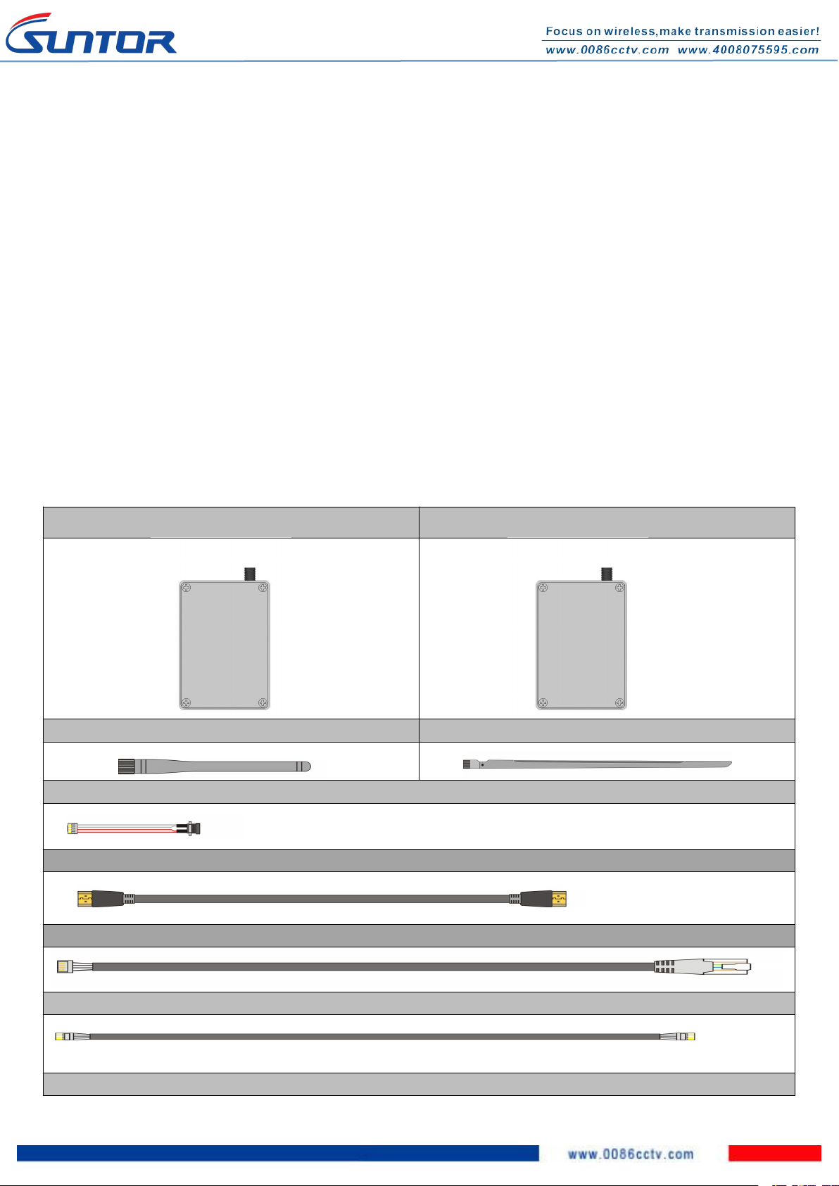
III. List of in-box items................................................................................................................................................................3rd
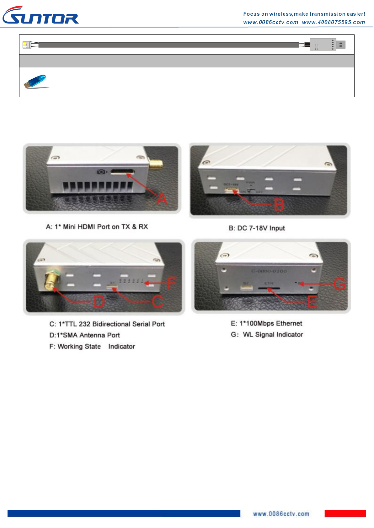
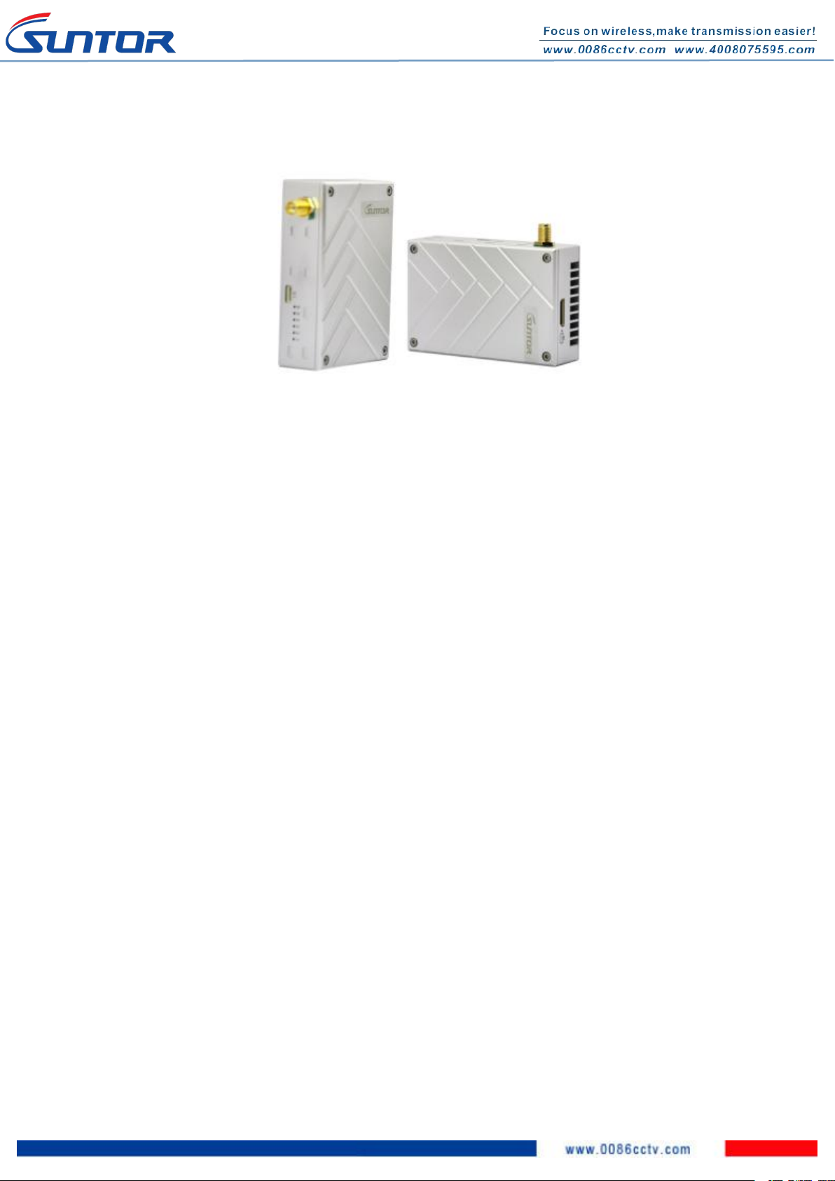
IV. Interface................................................................................................................................................................................ 4th
V. Precautions When Powering On............................................................................................................................................4th
VI. Operating Instructions & Steps............................................................................................................................................ 5th
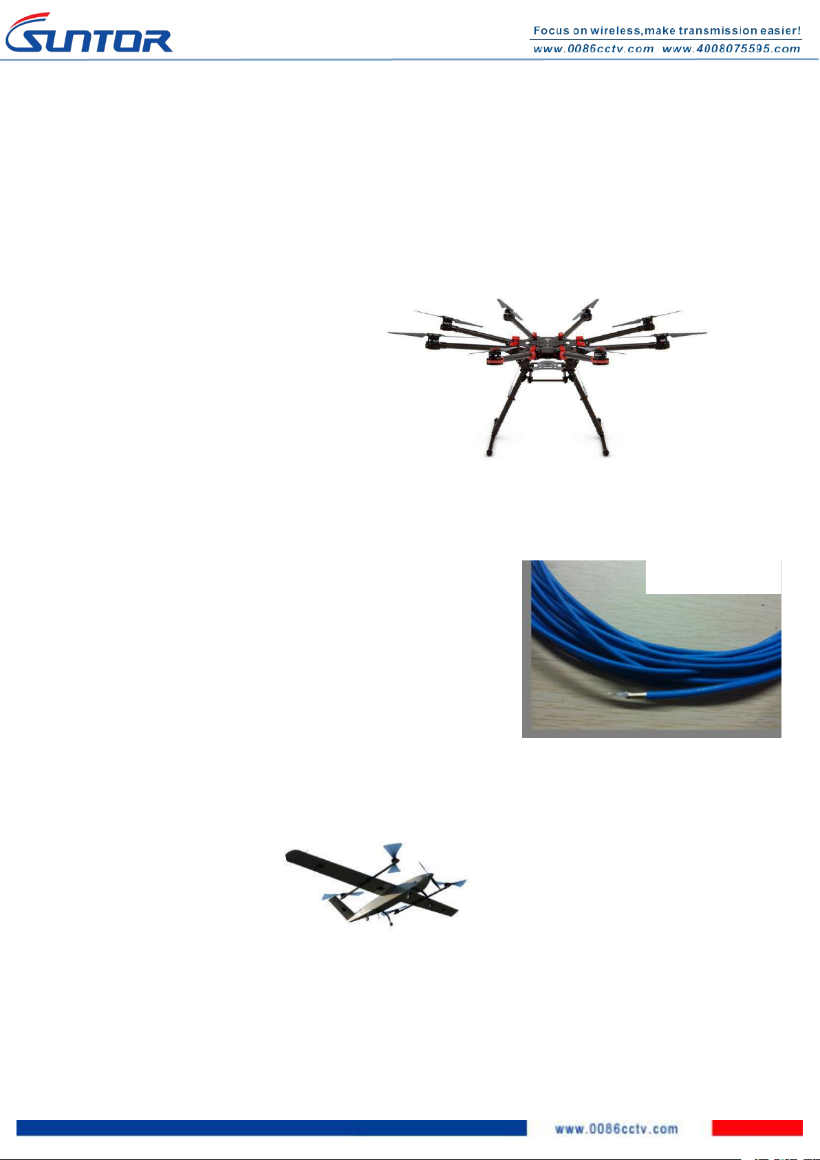
VII. Antenna Installation............................................................................................................................................................ 7th
1. Multi-rotor UAV............................................................................................................................................................. 7th
2. Fixed Wing UAV..............................................................................................................................................................7th
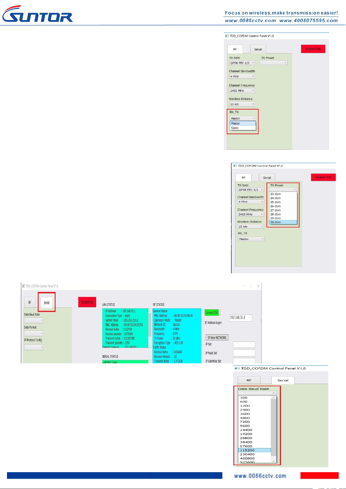
VIII. Software Operation............................................................................................................................................................ 8th
1. Start Connecting Tdd-cofdm equipment....................................................................................................................... 8th
2. Restart TDD-COFDM Control Panel software.............................................................................................................8th
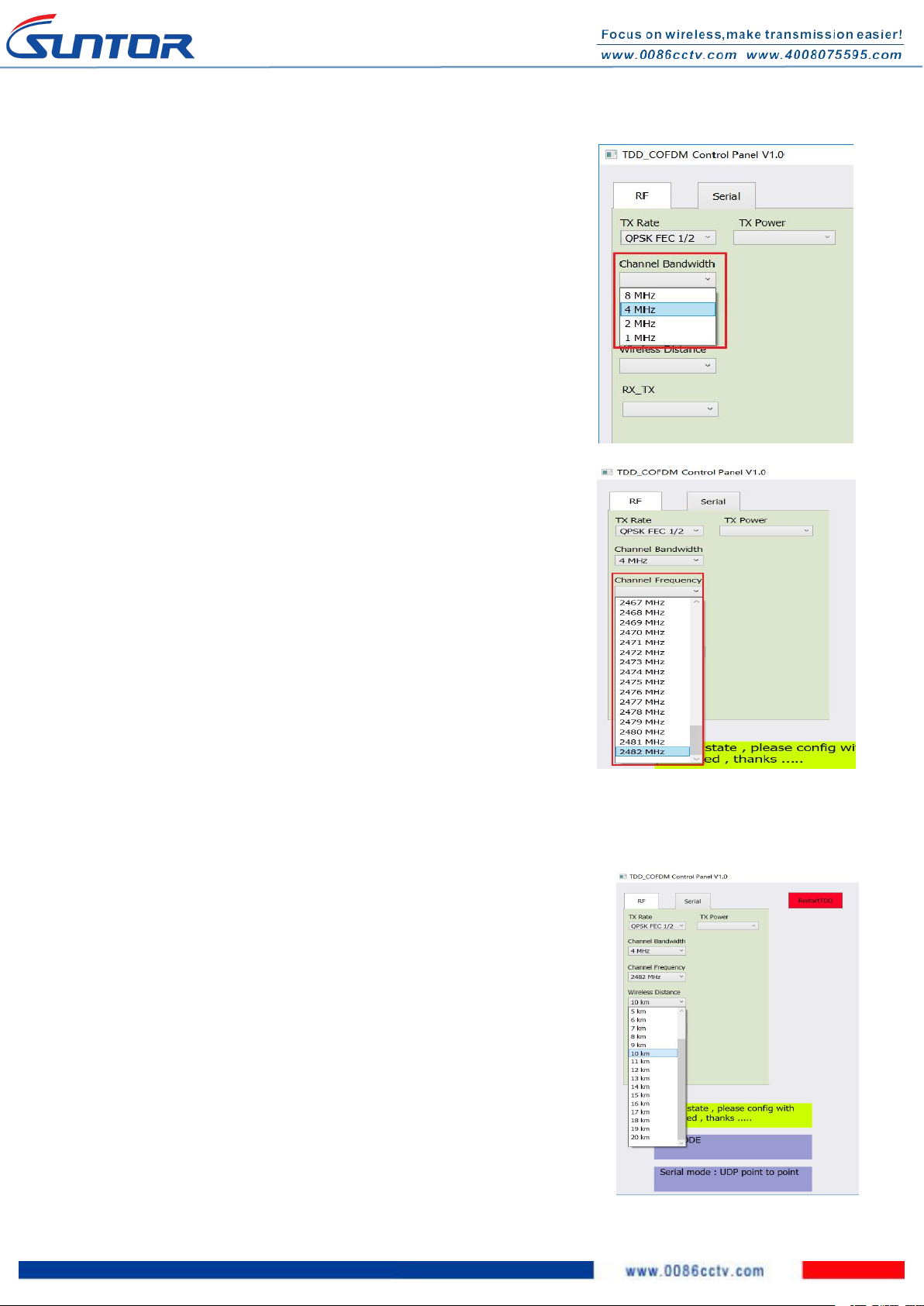
3. RF Configuration method..........................................................................................................................................8th
3. 1. TX Rate..............................................................................................................................................................8th
3.2. Channel Bandwidth............................................................................................................................................ 9th
3.3. Channel-Frequency.............................................................................................................................................9th
3.4. Wireless Distance............................................................................................................................................... 9th
3.5. RX TX Mode:...................................................................................................................................................10th
3.6. TX Power..........................................................................................................................................................10th
4. Seria Configuration method:....................................................................................................................................... 10th
4.1. Data Baud Rate.................................................................................................................................................10th
4.2. Data Format...................................................................................................................................................... 11th
4.3. IP Protocol Config............................................................................................................................................ 11th
5. RS232 Configuration Menu.........................................................................................................................................11th
6. IP New Network Configuration method:.................................................................................................................... 12th
7. RF New NET Configuration method.......................................................................................................................... 12th
7.1. RF Net ID:........................................................................................................................................................ 12th
7.2. RF Encrypt KEY ............................................................................................................................................ 12th
SUNTOR ELECTRONICS CO., LIMITED
V1.0

2nd
I. Disclaimer
SUNTOR is the registered trademark of SUNTOR ELECTRONICS CO., LIMITED. All product names and brands
in this manual are trademarks or registered trademarks of the Company. SUNTOR ELECTRONICS CO.,
LIMITED. reserves all copyrights of the product and the manual. All the information must not be copied or
reproduced in any form without permission of the Company. There may be semantic differences between
disclaimers of different languages. The Chinese version shall prevail in Chinese mainland, while the English
version shall prevail in other regions. Thank you for purchasing SUNTOR ST5/11/30HPT. Please use
ST5/11/30HPT according to local radio regulations. Before use, carefully read this disclaimer. Once the
product is used, all the contents of the disclaimer will be regarded recognized and accepted. Please install
and operate the product in strict accordance with the requirements of this manual. SUNTOR ELECTRONICS
CO., LIMITED and its affiliates will not assume any legal responsibility for results or losses caused by
improper use, installation, assembly and modification (including the use of non-specified SUNTOR parts
and accessories, such as the radio power amplifier, antenna and SMA extension cord).
Notes: Improper operation of ST5/11/30HPT may cause personal injury or damage to properties to some
extent. Pay attention to operation safety.
II. Precautions for integration
1. Be sure to use the parts provided by SUNTOR.
2. Please not reverse connect power line positive and negative. Or the device will be burn out.
3. Install the antenna before power on. Please not install or remove the antenna with power.
4. Given that the carbon fiber body and metal load may have shielding effects on antenna signals, they
should not be installed between the antenna and ground terminal. Keep the antenna of the on board
terminal free from winding or blocking by obstacles. The antenna end should be vertically downward
without bending, to prevent shortening of the communication distance and failure in communication
as a result of blocking.
5. The antennas of the onboard terminal should be separated from each other to achieve good
anti-jamming effects. It should be kept far away from antennas of other onboard radio transmitters, as
huge electromagnetic noise and interference may be caused between various radio antennas, which
will seriously shorten the communication distance, reduce the reliability of communication and even
cause failure in communication. It is recommended to use the functions of SUNTOR product, i.e. image
transmission and RS232 two-way serial port communication to minimize the quantity of onboard radio
devices.
6. Use the antenna of specified type, and properly install it. It is prohibited to use antennas of other
types.

3rd
7. To directly use the HDMI output of the PTZ camera, connect the PTZ holder after energizing and
self-testing, to avoid damage caused by rotation of the PTZ holder in self-testing to the HDMI cable. To
thoroughly solve this problem, it is preferred to use the split product, that is, the HDMI RX video
encoder board and PTZ camera are integrated with a short distance, and separated from the Ethernet
TX via the 4pin 100Mbps Ethernet cable. In this case, the reliability of HDMI signals between the PTZ
camera and HDMIRX video communication board will be greatly improved.
8. The HDMI cable and antenna may cause interference to GPS. They should be kept far away from the
GPS module and its cables as much as possible in the wiring process.
9. Do not disassemble or modify SUNTOR ST5/11/30HPT. Any problem during installation, contact
SUNTOR or the sales agent.
10. Keep appropriate distances between electronic devices during installation to minimize electromagnetic
interference.
III. List of in-box items
On board x1
Ground terminal x1
On board antenna x1
Ground antenna x1
4P-to-DC power cable x2
HDMI video cable x1
Network cable x1
TTL Serial port cable x2
USB cable of TTL serial port x1

4th
TPalyer Key
USB 2.0 Key
IV. Interface
Remark: The TX and RX have same interface specifications, All references are given above.
V. Precautions When Powering On
1. Before using, make sure that all cables are secure and reliably and all components can work properly.
2. After starting the product, check it for proper operation by observing whether the self-test indicator of
ST-3500HDis continuously ON for 30s and then flicker and whether the image of the camera is shown
on the ground terminal.

5th
3. Check the surrounding environment for to ensure there is no other 2.4GHz devices to cause
interference. If use the Futaba remote controller, the controller should be adjusted into the French
mode. Otherwise, the video transmission performance of ST5/11/30HPT may be serious affected and
also the Futaba transceiver may be in the abnormal status and accidents may be caused.
4. Remark: How to adjust the Futaba controller into French mode:
[LINKAGE MENU]→FRQUENCY→ RTN b→ [AREA]→[FRANCE]
5. Before use, check the electric quantity of the ground terminal. If the ground terminal is OFF, the
built-in radio receiver of the onboard terminal will be out-of-control.
6. Pay attention to the angle and direction of the antenna of the ground terminal during flight. In case of
poor signal or image quality, adjusting the inclination of the antenna of the ground terminal can
improve the signal or image effect.
7. The camera should be fully charged to ensure normal video output.
8. ST5/11/30HPT has the functions of two-way communication of image data and serial port data. If the
transmitted ground image is stuck or stopped for more than 10s but less than 30s, it means that the
radio channel signal is weakened or the radio channel is narrowed. In this case, the aircraft must not fly
farther away from the ground. In order to ensure the normal communication of serial data and the
safety of the aircraft, the distance between the aircraft and ground terminal should be immediately
shortened. Otherwise, the built-in radio receiver of the onboard terminal will be out-of-control.
9. 8. If required, purchase electronic devices (such as HD displays, Network cables, etc.) with good
electromagnetic shielding effects.
VI. Operating Instructions & Steps
1. Make TX and RX and accessories ready.
Besides the whole equipment we supply, you need to
also make sure the video source, display and power
ready before operating.

6th
2. Connection
3. Power on
After checking all the connections are in good condition, turn on the the video
source, LCD display, transmitter and receiver. The PWR indicator will bright and
the whole system start.
4. The status of all indicators during starting
When the device begin to normally start and work, all indicators status is described as follow:
1After power on, light 1,2,3 turn green, light 6 turns blue.
2After few seconds, light 1,2,3,6 start flashing.
And light 5 green is normally on.
3After a few seconds, the starting is complete.
Light 1(Green), 2(Green), 3(Green), 6(blue), 4(Red) are
normally on. Light 5 will fast blink.
4When data transmission goes well, WL green
light will flicker.
Remark:Light1, 2, 3 are indicator for signal strength.
1Light 1 on: Signal Weak
2Light 1,2 on: Signal Normal
3Light 1,2,3 on: Signal Strong
4When green light 1,2,3 repeatedly flash in sequence: No connection. The connection between TX and RX is failed
5Light 4 is Data connection light. If light 4 not bright, which means no data connection.
6When the transmission is normal, the WL light will normal on.
7After the receiver powered, the”POWER ON” letters will be showed on the display bottom right corner
5. Boot up successfully

7th
After successfully connection, the display will smoothly show the image.
Remark: In UAV application, please make the connection successfully then fly the UAV. About the right way of
installation antenna please refer to the following description.
VII. Antenna Installation
1. Multi-rotor UAV
1) To select the original antenna and the SMA metal shielded semi-flexible blue feeder cable provided by
SUNTOR. The feeder cable is used to connect the TX SMA port and the antenna.
2) The antenna needs to be mounted vertically downwards, and it
is not recommended to mount it vertically at the top of the UAV.
3) The best installation location is the UAV ground bracket. With
the antenna inside the bracket can only use fiberglass material.
4) If the ground bracket is automatically retracted, the antenna can
be installed in the lower part of the aircraft, and the ground RX
antenna is recommended to use same antenna with TX( 29cm
length antenna).
5) If the antenna is intercepted by the camera or pod or the loudspeaker, the video on RX will appear
image stuck or mosaic and It is recommended to immediately adjust the flight attitude and angle.
2. Fixed Wing UAV
1) To select the original antenna and the SMA metal shielded semi-flexible blue feeder cable provided by
SUNTOR. The feeder cable is used to connect the TX SMA port and the antenna.
2) The antenna needs to be mounted vertically downwards, and it is not recommended to mount it
SMA Feeder Cable

8th
vertically at the top of the UAV.
3) It is recommended to use 29cm long antenna. The best installation position is the center of the UAV tail,
prominent outside the body and vertical downward.
4) The second optional mounting position is located below the wing and body joints, vertical down, as far
as possible away from the wing but near the machine abdomen, protruding below the abdomen level.
VIII. Software Operation
1. Start Connecting Tdd-cofdm equipment
First, enter the IP address,Next click Connect TDD button.
2. Restart TDD-COFDM Control Panel software:click Restart TDD button.
3. RF Configuration method
3. 1. TX Rate(Default:QPSK FEC 1/2):
This setting determines the modulation type and in turn the rate at which the data is to be
wirelessly transferred. The default and recommended setting for both Master and Slave
units is ‘Auto’. When in ‘Auto’ the unit will transfer data at the highest possible rate in
consideration of the receive signal strength (RSSI).
Refer to Performance for a table breakdown of performance at selected rates. If setting a
fixed TX Rate It is recommended to retain a fade margin of at least 10 dbm for optimum

9th
performance. For example, for a link (8MHz channel) with a signal strength of at least –75dBm, a TX rate of 16-QAM 3/4
FEC is recommended. Setting to the highest rate with a poor link may result in reduced performance.
3.2. Channel Bandwidth(Default:4Mhz):
Select the channel bandwidth from the list. Refer to the specifications to see
the relationship and performance between channel band, width,throughput
and sensitivity.Generally a larger channel has greater throughput, at the cost of
sensitivity, while a smaller channel tends to be more robust, but at the cost of
throughput.
3.3. Channel-Frequency(Default:2479Mhz):
2402 - 2482 (1MHz BW, CH 1-81)
2402 - 2482 (2MHz BW, CH 1-81)
2405 - 2479 (4MHz BW, CH 4-78)
2407 - 2477 (8MHz BW, CH 6-76)
3.4. Wireless Distance(Default:10km):
The Wireless Distance parameter allows a user to set the expected distance the
wireless signal needs to travel. The TDD-COFDM sets various internal timeouts to
account for this travel time. Longer distances will require a higher setting, and
shorter distances may perform better if the setting is reduced.

10th
3.5. RX TX Mode:
TX Master - A Master may provide a wireless data connection to many slaves
RX Slave- A Salve may sustain one wireless connection,i.e. to an Master.
3.6. TX Power(Default:30dbm):
This setting establishes the transmit power level which will be presented to the
antenna connector of the TDD_COFDM.Unless required, the Tx Power should be
set not for maximum, but rather for the minimum value required to maintain an
adequate system fade margin.
4. Seria Configuration method:
4.1. Data Baud Rate(Default:115200):
The serial baud rate is the rate at which the modem is to communicate with the
attached local asynchronous device.
921600/460800/230400/115200/57600/38400/28800/19200/14400/9600/7200/4
800/3600/2400/1200/600/300.

11th
4.2. Data Format(Default:8N1):
This setting determines the format of the data on the serial port.
The default is 8 data bits, No parity, and 1 Stop bit.
8N1
8E1
8O1
4.3. IP Protocol Config(Default:UDP Point to Point):
This setting determines which protocol the serial server will use to transmit serial
port data over the TDD-COFDM network.The protocol selected in the IP Protocol
Config field will determine which configuration options appear in the remainder of
the
5. RS232 Configuration Menu.
TCP Client: When TCP Client is selected and data is received on its serial port, the TDD-COFDM takes the initiative to find
and connect to a remote TCP server. The TCP session is terminated by this same unit when the data exchange session is
completed and the connection timeout has expired. If a TCP
connection cannot be established, the serial port data is discarded.
UDP Point-to-Point: In this configuration the TDD-COFDM will send serial data to a specifically-defined point,using UDP
packets. This same TDD-COFDM will accept UDP packets from that same point.
Remote IP Address
IP address of distant device to which UDP packets are sent when data received at serial port.
Default: 192.168.55.1(master);192.168.55.2(slave).
Remote Port
UDP port of distant device mentioned above.
Default: 20002
Listening Port
UDP port which the IP Series listens to (monitors). UDP packets received on this port are forwarded to the unit’s serial port.
Default: 20002
UDP Timeout(s)
UDP Timeout in seconds.
Default: 10

12th
6. IP New Network Configuration method:
This setting helps you to change the IP address of devices .The default of master’s IP address is 192.168.55.1,the default
of slaver’s IP address is 192.168.55.2.
For example,you want to change the master’s IP address to “192.168.55”. Then do
as the following steps.
IP Set : 192.168.55.5
IP Mask Set: 255.255.255.0
IP Gateway Set: 192.168.55.1
Next Connect IP NEW NETWORK button.
Attention! When you have changed the IP address ,you should correct another
device ‘s “Remote IP Addr” into the same “IP SET”, or the serial port will lose
connection.
For example , you have changed the master’s IP address to “192.168.55.5”, the you
should correct the salver’s “Remote IP Addr” to “192.168.55.5”.
7. RF New NET Configuration method:
7.1. RF Net ID:
Each network of TDD-COFDM modules must have a unique Network ID. This
Network ID must be set in each unit on the network.
7.2. RF Encrypt KEY
This is the password, or preshared key that is required by any device to connect to the wireless interface of the
TDD-COFDM. It is strongly recommended to always have a password defined, and changed from the factory default.
This manual suits for next models
3
Table of contents
Other Suntor Receiver manuals