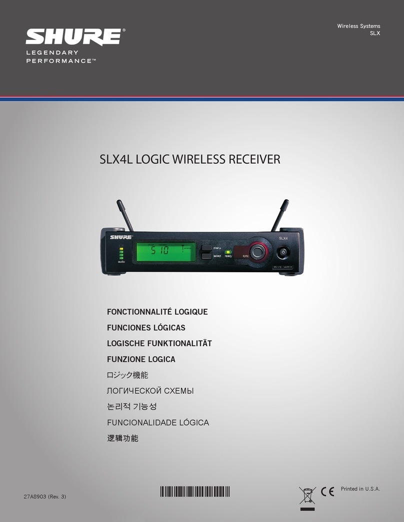
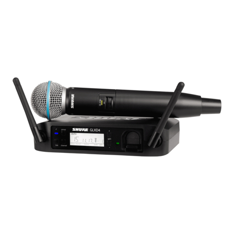
Shure BLX4R User manual

©2013 Shure Incorporated
27A21197 (Rev. 3) Printed in U.S.A.
BLX4R Wireless Receiver
BLX4Rワイヤレス受信機
BLX4R 무선 수신기
Receiver Nirkabel BLX4
BLX4R 无线接收机
BLX4R 無線接收機


IMPORTANT SAFETY INSTRUCTIONS
1. READ these instructions.
2. KEEP these instructions.
3. HEED all warnings.
4. FOLLOW all instructions.
5. DO NOT use this apparatus near water.
6. CLEAN ONLY with dry cloth.
7. DO NOT block any ventilation openings. Allow sufficient distances for adequate ventila-
tion and install in accordance with the manufacturer’s instructions.
8. DO NOT install near any heat sources such as open flames, radiators, heat registers,
stoves, or other apparatus (including amplifiers) that produce heat. Do not place any open
flame sources on the product.
9. DO NOT defeat the safety purpose of the polarized or groundingtype plug. A polarized
plug has two blades with one wider than the other. A grounding type plug has two blades
and a third grounding prong. The wider blade or the third prong are provided for your
safety. If the provided plug does not fit into your outlet, consult an electrician for replace-
ment of the obsolete outlet.
10. PROTECT the power cord from being walked on or pinched, particularly at plugs, conve-
nience receptacles, and the point where they exit from the apparatus.
11. ONLY USE attachments/accessories specified by the manufacturer.
12. USE only with a cart, stand, tripod, bracket, or table specified by the manu-
facturer, or sold with the apparatus. When a cart is used, use caution when
moving the cart/apparatus combination to avoid injury from tip-over.
13. UNPLUG this apparatus during lightning storms or when unused for long
periods of time.
14. REFER all servicing to qualified service personnel. Servicing is required when the ap-
paratus has been damaged in any way, such as power supply cord or plug is damaged,
liquid has been spilled or objects have fallen into the apparatus, the apparatus has been
exposed to rain or moisture, does not operate normally, or has been dropped.
15. DO NOT expose the apparatus to dripping and splashing. DO NOT put objects filled with
liquids, such as vases, on the apparatus.
16. The MAINS plug or an appliance coupler shall remain readily operable.
17. The airborne noise of the Apparatus does not exceed 70dB (A).
18. Apparatus with CLASS I construction shall be connected to a MAINS socket outlet with a
protective earthing connection.
19. To reduce the risk of fire or electric shock, do not expose this apparatus to rain or
moisture.
20. Do not attempt to modify this product. Doing so could result in personal injury and/or
product failure.
21. Operate this product within its specified operating temperature range.
This symbol indicates that dangerous voltage constituting a risk of
electric shock is present within this unit.
This symbol indicates that there are important operating and mainte-
nance instructions in the literature accompanying this unit.
WARNING: This product contains a chemical known to the State of California to cause cancer and birth
defects or other reproductive harm.
安全のための重要注意事項
1. この説明書をお読みください。
2. この説明書を保管しておいてください。
3. 警告事項すべてに留意してください。
4. す べ て の 指 示 に 従 っ て く だ さ い 。
5. この製品は 水の近くで使 用しないでください。
6. 掃 除 は 、乾 い た 布 で か ら 拭 き す る だ け に し て く だ さ い 。
7. 通風口を塞がないようにしてください。十分な換気ができるよう余裕を持たせ、メーカー
の指示に従って設置してください。
8. 炎、ラジエーターや暖房送風口、ストーブ、その他、熱を発生する機器 (アンプなど) の
近くには設置しないでください。炎が出る物を製品の上に置かないでください。
9. 有極プラグやアース付きプラグは安全のために用いられています。無効にしないように
してください。有極プラグは、2本のブレードのうち一方が幅広になっています。アース付
きプラグは、2本のブレードの他に、3本目のアースの棒がついています。幅広のブレード
や3本目の棒は、安全のためのものです。これらのプラグがコンセントの差し込み口に合
わない場合は、電気工事業者に相談し、コンセントを交換してもらってください。
10. 電源コードは、特にプラグ差し込み部分、延長コード、機器から出ている部分において、
引っか かって 抜 け たり挟 ま れ たりし ない ように保 護し てください 。
11. アタッチメントや付属品は、必ずメーカー指定のものをご利用ください。
12. カートやスタンド、三脚、ブラケット、テーブル等は、メーカー指定のものか、こ
の装置用に販売されているものを必ずご利用ください。カートに装置を載せ
て動かす際は、つっかけて怪我をしないよう注意してください。
13. 雷を伴う嵐の際、または長期間使用しない場合は、プラグをコンセントから抜いてくだ
さ い 。
14. 整備の際は、資格のある整備担当者に必ずご相談ください。電源コードやプラグの損
傷、液体や異物が装置内に入り込んだ場合、装置が雨や湿気に曝された場合、正常に
作動しない場合、装置を落とした場合など、装置が何らかの状態で損傷した場合は、
整備が必要です。
15. 水滴や水しぶきに曝さないでください。液体の入った花瓶などを装置の上に置かない
で く だ さ い 。
16.
MAINSプラグまたはアプライアンスカップラーが使用できる状態にしておいてください。
17. 装置の空気伝播音は70 dB(A)を超えません。
18. クラスI構造の装置は保護接地接続のある主電源の壁コンセントに接続してください。
19. 火災や感電の危険を避けるため、本機器は雨や湿気のある場所にさらさないでくださ
い 。
20. 本製品の改造は試みないでください。改造した場合、怪我や製品故障の原因となるこ
とが ありま す 。
21. 本製品は指定された動作温度範囲内で使用してください。
警告。この表示内容を無視して誤った取り扱いをすると、死亡または重
傷を負う可能性が想定される内容です。
注意。この表示内容を無視して誤った取り扱いをすると、傷害を負う可
能性または物的損害が発生する可能性が想定される内容です。
중요 안전 지침
1. 이 지침을 정독해 주십시오.
2. 이 지침을 잘 보관해 주십시오.
3. 모든 경고에 유의하십시오.
4. 모든 지침을 준수하십시오.
5. 이 기기를 물 가까이에 두고 사용하지 마십시오.
6. 마른 수건으로만 닦으십시오.
7. 통풍구를 막지 마십시오. 적합한 환기를 위해 충분히 거리를 두고 제조업체의 안내
서에 따라 설치하십시오.
8. 개방된 화염, 난방기, 방열 조절기, 스토브, 기타 열을 발산하는 기기 (앰프포함) 등
의 열원 근처에 설치하지 마십시오. 제품 위에 개방된 화염원을 올려 놓지 마십시오.
9. 안전을 위해 유극 또는 접지 타입의 플러그를 반드시 사용하십시오. 유극 유형의 플
러그는 넓은 핀과 좁은 핀, 두 개의 핀으로 구성되어 있습니다. 접지형 플러그에는
두 개의 핀과 하나의 접지 단자가 있습니다. 넓은 핀이나 접지 단자는 사용자의 안전
을 위한 것입니다. 제공된 플러그가 콘센트에 맞지 않으면 전기 기사에게 문의하여
콘센트를 교체하십시오.
10. 전원 코드는 밟히지 않도록 주의하고 특히 전원 플러그 사이, 접속 소켓 및 기기에서
나오는 부분에 전원 코드가 끼이지 않도록 보호하십시오.
11. 제조업체가 지정한 부속품/액세서리만 사용하십시오.
12. 제조업체에서 지정하거나 기기와 함께 판매되는 카트, 스탠드, 받침대, 브
라켓 또는 테이블에서만 사용하십시오. 카트를 사용하는 경우, 이동 시 카
트와 기기가 넘어져 부상을 입지 않도록 주의하십시오.
13. 낙뢰시 또는 장기간 사용하지 않을 때는 기기의 전원을 빼놓으십시오.
14. 모든 서비스는 자격을 갖춘 서비스 전문가에게 의뢰하십시오. 전원 코드나 플러그
가 손상된 경우, 기기 안으로 액체가 들어가거나 물건을 떨어뜨린 경우, 기기가 비나
물에 젖은 경우, 기기가 정상적으로 작동하지 않는 경우 또는 기기를 떨어뜨린 경우
와 같이 기기가 손상되었을 때는 서비스를 받아야 합니다.
15. 기기에 물을 떨어뜨리거나 뿌리지 마십시오. 화병과 같이 물이 담긴 물체를 기기 위
에 올려놓지 마십시오.
16. MAINS 플러그나 기기용 커플러는 작동가능한 상태로 남아 있어야 합니다.
17. 기기의 공기매개 잡음은 70dB을 초과하지 않아야 합니다.
18. CLASS I 구조의 기기는 MAINS 소켓 콘센트에 보호 접지 연결 방식으로 연결되어
야 합니다.
19. 화재나 감전 위험을 줄이려면 이 기기를 빗물 또는 습기에 노출시키지 마십시오.
20. 이 제품을 고치려고 시도하지 마십시오. 그렇게 하면 사람이 다치거나 제품이 고장
을 일으킬 수 있습니다.
21. 이 제품은 명시된 작동 온도 범위내에서 사용하십시오.
이 기호는 기기에 전기 쇼크 위험을 유발하는 위험한 전압이
흐른다는 것을 의미합니다.
이 기호는 이 기기와 함께 제공된 문서에 중요한 작동 및 유지
보수 지침의 내용이 들어 있다는 것을 의미합니다.
PETUNJUK PENTING KESELAMATAN
1. BACA petunjuk ini.
2. SIMPAN petunjuk ini.
3. PATUHI semua peringatan.
4. IKUTI semua petunjuk.
5. JANGAN gunakan perangkat ini dekat dengan air.
6. CUKUP DIBERSIHKAN dengan kain lap kering.
7. JANGAN halangi semua bukaan ventilasi. Biarkan jarak yang cukup dengan lubang
udara yang cukup dan pasang sesuai petunjuk pabrik.
8. JANGAN pasang dekat dengan sumber panas seperti radiator, kisi-kisi tungku pemanas,
kompor, atau perangkat lain (termasuk amplifier) yang menghasilkan panas. Jangan
taruh sumber api terbuka pada produk ini.
9. JANGAN gagalkan tujuan keamanan steker terpolarisasi atau jenis pembumian. Steker
terpolarisasi memiliki dua bilah di mana bilah yang satu lebih lebar dari yang lain. Steker
jenis pembumian memiliki dua bilah dan tonjolan pembumian ketiga. Bilah yang lebih
lebar atau tonjolan ketiga disediakan untuk keselamatan Anda. Jika steker yang dise-
diakan tidak cocok dengan stopkontak Anda, hubungi petugas listrik untuk penggantian
stopkontak yang sudah lama itu.
10. LINDUNGI kabel listrik agar aman dari injakan atau jepitan, terutama pada steker, stop-
kontak terbuka, dan titik yang menonjol dari perangkat itu.
11. HANYA GUNAKAN kelengkapan/aksesoris yang ditetapkan pabrik.
12. GUNAKAN hanya dengan kereta dorong, penyangga, tripod, braket atau
meja yang ditetapkan oleh pabrikan, atau yang dijual bersama perangkat
tersebut. Bila menggunakan kereta dorong, gunakan secara hati-hati ketika
memindahkan secara bersama-sama kereta dorong/perangkat tersebut untuk
menghindari cedera karena perangkat terguling.
13. CABUT perangkat ini selama petir atau bila tidak digunakan untuk waktu yang lama.
14. SERAHKAN semua servis ke petugas ahli. Servis diperlukan apabila perangkat tersebut
sudah rusak dalam cara apapun, seperti kabel catu daya atau steker rusak, cairan ter-
tumpah atau ada benda yang jatuh ke dalam perangkat, perangkat sudah terpapar hujan
atau lembab, tidak bekerja normal, atau perangkat pernah jatuh.
15. JANGAN paparkan perangkat dengan tetesan dan percikan. JANGAN letakkan benda
yang penuh dengan cairan, seperti pot bunga di atas perangkat tersebut.
16. Steker INDUK atau tusuk kontak harus tetap siap digunakan.
17. Kebisingan Perangkat ini yang bersumber dari udara tidak melebihi 70dB (A).
18. Perangkat dengan konstruksi KELAS I harus dihubungkan ke stopkontak soket INDUK
dengan sambungan pembumian untuk pengaman.
19. Untuk mengurangi resiko kebakaran atau sengatan listrik, jangan paparkan perangkat ini
dengan hujan atau lembab.
20. Jangan coba-coba memodifikasi produk ini. Melakukannya dapat menyebabkan cedera
diri dan/atau kerusakan produk.
21. Jalankan produk ini di dalam jarak suhu kerja yang ditetapkan.
Simbol ini menunjukkan bahwa voltase yang berbahaya menimbulkan
resiko atau sengatan yang ada di dalam unit ini.
Lambang ini menunjukkan bahwa terdapat petunjuk kerja dan pemeli-
haraan penting pada bacaan yang melengkapi unit ini.
重要安全事项!
1. 必须阅读这些注意事项。
2. 必须保留这些注意事项。
3. 必须注意所有警告内容。
4. 必须遵循所有注意事项。
5. 不要在靠近水的地方使用本设备。
6. 只能用干布擦拭设备。
7. 不要堵塞任何通风口。留出足够的距离,确保充分通风,并安装在符合制造
商要求的位置。
8. 不要将本设备安装在任何热源(如明火、散热器、调温器、火炉或包括功率
放大器在可的其它可能产生热量的装置附近。不要将任何明火火源放置在产
品上。
9. 不要破坏带极性或接地类型插头的安全功能。极性插头带有两个插片,其中一
个比另一个宽。接地类型插头带有两个插片和第三个接地插脚。较宽的插片或
第三个插脚是为安全目的设置的。如果提供的插头无法插入您的插座,请向电
工咨询如何更换合适的插座。
10. 保护电源线防止被脚踩踏或被夹紧,尤其是在插头、方便插座和机身电源线
的引出处。
11. 只能使用制造商指定的连接部件/附件。
12. 只能使用制造商指定的或随设备售出的手推车、支座、三角架、托
架或支撑台。如果使用手推车,在移动装有设备的手推车时应注意
安全,避免设备翻落。
13. 在雷电天气或长时间不使用情况下,应拔下设备插头。
14. 所有维修均应由合格的维修人员执行。如果设备因下列情况损坏,应进行维
修:电源线或插头损坏、液体泼溅到设备上或异物进入设备,设备暴露在雨水
或潮湿环境中而无法正常工作,或摔落到地上。
15. 不要将本设备暴露在可能滴水和溅水的地方。不要将装有液体的容器(如花瓶
等)放在本设备顶部。
16. 电源插头或电器转接头应保持在随时可用的状态。
17. 本装置的空气噪声不超过 70dB (A)。
18. 应将符合 I 类标准的设备连接到带有接地保护装置的主电源插座。
19. 为降低起火或电击危险,不要将本设备暴露在雨中或潮湿环境下。
20. 不要尝试改装本产品。否则可能会导致人身伤害和/或产品故障。
21. 应在技术规格指定的温度范围内操作此产品。
这个符号表示本设备中存在可能导致触电的危险电压。
这个符号表示本设备附带的说明书中具有重要的操作和维护
说明。
重要安全事項!
1. 必須閱讀這些注意事項。
2. 必須保留這些注意事項。
3. 必須注意所有警告內容。
4. 必須遵循所有注意事項。
5. 不要在靠近水的地方使用本設備。
6. 只能用幹布擦拭設備。
7. 不要堵塞任何通風口。留出足夠的距離,確保充分通風,並安裝在符合製造
商要求的位置。
8. 不要將本設備安裝在任何熱源(如明火、散熱器、調溫器、火爐或包括功率
放大器在可的其它可能產生熱量的裝置附近。不要將任何明火火源放置在產
品上。
9. 不要破壞帶極性或接地類型插頭的安全功能。極性插頭帶有兩個插片,其中一
個比另一個寬。接地類型插頭帶有兩個插片和第三個接地插腳。較寬的插片或
第三個插腳是為安全目的設定的。如果提供的插頭無法插入您的插座,請向電
工咨詢如何更換合適的插座。
10. 保護電源線防止被腳踩踏或被夾緊,尤其是在插頭、方便插座和機身電源線
的引出處。
11. 只能使用製造商指定的連接部件/附件。
12. 只能使用製造商指定的或隨設備售出的手推車、支座、三角架、托
架或支撐台。如果使用手推車,在移動裝有設備的手推車時應注意
安全,避免設備翻落。
13. 在雷電天氣或長時間不使用時,應拔下設備的插頭。
14. 所有維修均應由合格的維修人員執行。在設備因以下情況被損壞時,應進行維
修:電源線或插頭損壞、液體潑濺到設備上或異物進入設備,設備暴露在雨水
或潮濕環境中而無法正常工作,或摔落到地上。
15. 不要將本設備暴露在可能滴水和濺水的地方。不要將裝有液體的容器(如花瓶
等)放在本設備頂部。
16. 電源插頭或電器轉接頭應保持在隨時可用的狀態。
17. 本裝置的空氣噪聲不超過 70dB (A)。
18. 應將符合 I 類標準的設備連接到帶有接地保護裝置的主電源插座。
19. 為降低起火或電擊危險,不要將本設備暴露在雨中或潮濕環境下。
20. 不要嘗試改裝本產品。否則可能會導致人身傷害和/或產品故障。
21. 應在技術規格指定的溫度範圍內操作此產品。
這個符號表示本設備中存在可能導致觸電的危險電壓。
此符號表示本部件附帶的說明書中具有重要的操作和安全說
明。

group
(A-Y)
a)
b)
ANTENNA B POWER MIC OUT INSTRUMENT OUT VOLUME ANTENNA A
① ②
ANTENNA B POWER MIC OUT INSTRUMENTOUT VOLUME ANTENNA A
① ② BLX4R
group channel
(A-Y) (0-9)
BLX4R
group channel
(A-Y) (0-9)
受信機を電源に接続します。
受信機をミキサーまたはアンプに接続します。電源
ボタンを押して受信機をオンにします。
受信機のグループボタンを押して、グループ
スキャンを実行します。
수신기를 전원에 연결합니다.
수신기를 믹서나 앰프에 연결합니다. 전원 버튼을 눌
러 수신기를 켭니다.
그룹 스캔을 실행하려면 수신기의 그룹 버튼
을 누릅니다.
Sambungkan receiver ke sumber daya.
Sambungkan receiver ke mixer atau amplifier.
Tekan tombol daya untuk menghidupkan receiver.
Tekan tombol grup pada receiver untuk me-
mindai grup.
将接收机连接到电源。
将接收机连接到混音器或放大器。按下电源按钮可打
开接收机电源。
按下接收机上的组按钮,执行组扫描。
將接收機連接到電源。
將接收機連接到混音器或放大器。按下電源按鈕打開
接收機電源。
按下接收機上的組按鈕,執行組掃描。
5
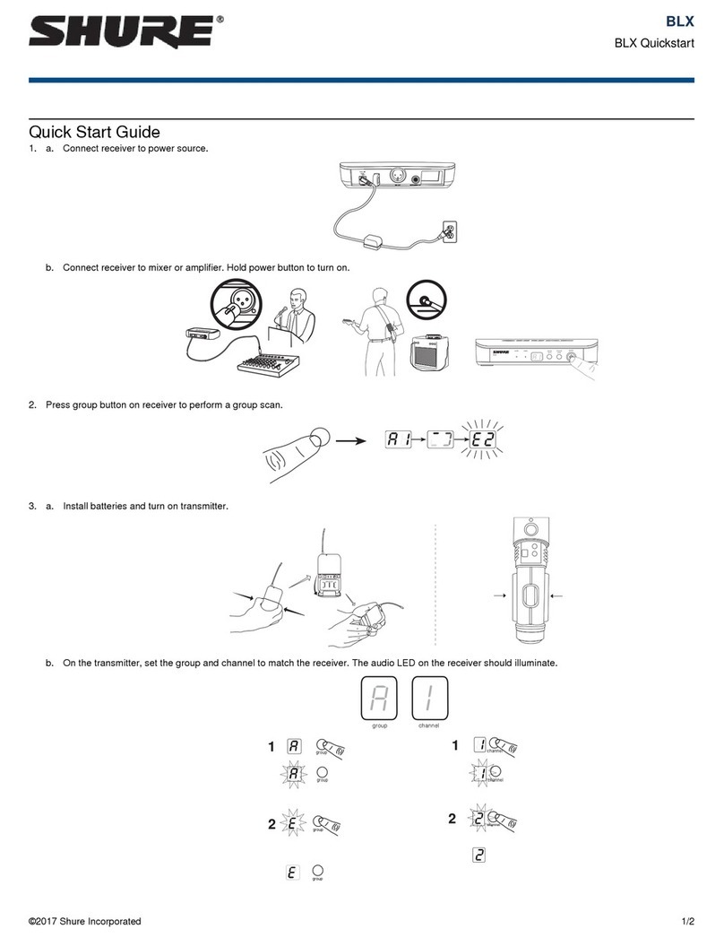
Quick Start Guide
Connect receiver to power source.
Connect receiver to mixer or amplifier. Press the
power button to turn on the receiver.
Press group button on receiver to perform
a group scan.

group
(A-Y)
channel
(0-9)
a)
b)
channel
group
group channel
channel
group
group
group channel
送信機に電池を入れ、オンにします。
送信機で、グループとチャンネルを設定して
受信機に合わせます。受信機のRFバーと電池
LEDが点灯します。
건전지를 설치한 다음 송신기를 켜십시오.
송신기에 그룹과 채널을 설정하여 수신기에 일
치시키십시오. 수신기의 RF 바와 건전지 LED
에 불이 들어와야 합니다.
Pasang baterai dan hidupkan pemancar.
Pada pemancar, atur grup dan saluran untuk
menyesuaikan dengan receiver. Bilah FR
dan lampu LED baterai pada receiver harus
menyala.
安装电池并打开发射机电源。
在发射机上,将组和频道设置为与接收机匹配。接
收机上的射频指示灯条和电池指示灯应点亮。
安裝電池並打開發射機電源。
在發射機上,將組和頻道設定為與接收機匹配。接
收機上的 RF 指示燈條和電池指示燈應點亮。
6
Install batteries and turn on transmitter.
On the transmitter, set the group and
channel to match the receiver. The RF bars
and battery LED on the receiver should
illuminate.

5 s
channel group
-10 dB
-10 dB
channel group
group
(A-Y)
channel
(0-9)
追加システムを設定する場合は、最初の送信機と受信機をオンにした状態にしてください。各追加受信機ごとに、グループ
を手動で設定して最初の受信機に合わせてください。注記:受信機は自動的にチャンネルスキャンを実行し、グループを選
択したら利用可能な周波数を検出します。送信機周波数を設定して受信機に一致させます。
音が小さすぎる場合や歪む場合は、ゲインを
適宜調整してください。
추가 시스템을 설정하면 첫 번째 송신기와 수신기를 켠 상태로 두십시오. 각 추가 수신기마다 수동으로 첫 번째 송신기와 일치
하는 그룹을 설정하십시오. 주: 그룹이 선택되면 수신기가 자동으로 채널 스캔을 수행하여 사용 가능한 주파수를 찾습니다. 송
신기 주파수를 수신기에 일치시킵니다.
사운드가 너무 흐리거나 왜곡된다면 게인을 조
절하십시오.
Jika mengatur sistem tambahan, biarkan pemancar dan receiver pertama hidup. Untuk setiap receiver tambahan, atur grup
secara manual untuk mencocokkan receiver pertama. Catatan: Receiver akan melakukan pemindaian saluran secara otom-
atis untuk mendapatkan frekuensi yang tersedia setelah grup dipilih. Atur frekuensi pemancar untuk mencocokkan receiver.
如果要设置更多的系统,应让第一台发射机和接收机保持在打开状态。对于每个增加的接收机,因将组手动设置为与第一台
接收机匹配。注意:接收机可自动纸箱厂频道扫描,在选取组之后找到可用的频率。将发射机的频率设置为与接收机匹配。
如果声音太模糊或失真,应相应地调节增益设置。
如果需要額外設定更多系統,應讓第一台發射機和接收機保持打開。對於每台增加的接收機,都需要手動將組設定為與第一
台接收機匹配。注意:接收機將自動執行頻道掃描,在選取組之後找到可用的頻率。選擇與接收機匹配的發射機頻率。
如果聲音太模糊或失真,應相應地調節增益設定。
Jika suara terlalu lemah atau terdistorsi, sesuaikan
penguatan sesuai dengan itu.
7
If setting up additional systems, leave the first transmitter and receiver on. For each additional receiver, manually set the
group to match the first receiver. Note: The receiver will automatically perform a channel scan to find an available frequency
after the group has been selected. Set the transmitter frequency to match the receiver.
If sound is too faint or distorted, adjust the
gain accordingly.

tv
group channel rf
A
OL
B
audio
OL
7
5 6
34
2
1
BLX4R
group channel
(A-Y ) (0-9)
798 1110
3
21 5 6 12
4
ANTENNA B POWER MIC OUT INSTRUMENT OUT VOLUME ANTENNA A
8
Front Panel Rear Panel
① Transmitter Battery LED
• Green = Runtime greater than 1 hour
• Red = Runtime less than 1 hour
② LCD Display
Displays receiver and transmitter settings.
③ group Button
• Scan: push and release group button to
scan for an open group and channel
• Manual: push and hold group button to
select a group.
④ channel Button
• Scan: push and release channel button to
scan for an open channel
• Manual: push and hold channel button to se-
lect a channel.
⑤ Power Button
Powers the receiver on/off.
⑥ Antenna Jack B
BNC connector for antenna B.
⑦ DC Power Jack
For DC external power supply (12 to 15 V DC).
⑧ Strain-relief loop for power cord
Secures power cord to receiver.
⑨ Mic Out XLR audio output jack
Supplies microphone-level audio output.
⑩ INST Out audio output jack
Supplies instrument-level audio signal.
⑪ Volume Control
Use a screwdriver to adjust the output
level.
⑫ Antenna Jack A
BNC connector for antenna A.
Receiver LCD Screen
① TV Channel
TV channel for selected frequency.
② Receiver Lock
Indicates control and power lock enabled.
③ Group
Displays selected group.
④ Channel
Displays selected channel.
⑤ RF Signal Strength
Number of bars corresponds to RF signal strength. OL indicates
signal overload.
⑥ Audio Meter
Number of bars indicates audio signal level. OL indicates signal
clipping.
⑦ Active Antenna Indicator
Indicates active antenna for the diversity signal.
BLX4R Receiver

BLX1
group
(A-Y)
channel
(0-9)
①
②④
⑤
⑥
⑦⑧
⑨
③
BLX2
channel group
-10 dB
③ ④
⑥
⑦
⑤
①
②
9
BLX1
① LED Indicator
Displays power and battery status (see table).
② power Switch
Toggles power on or off.
③ 4-Pin Microphone Input Jack (TA4 connector)
④ Antenna
⑤ group Button
Changes group setting.
⑥ LED Display
Displays group and channel setting.
⑦ channel Button
Changes channel setting.
⑧ Battery Compartment
⑨ Audio Gain Adjustment
Rotate to increase or decrease transmitter gain.
BLX2
① LED Indicator
Displays power and battery status (see table).
② power Button
Push to turn power on or off.
③ group Button
Changes group setting.
④ channel Button
Changes channel and gain setting.
⑤ LED Display
Displays group and channel setting.
⑥ Identification Cap
⑦ Battery Compartment
Transmitter LED Indicators
Transmitters
LED Indicator Status
Green Ready
Rapidly Flashing Red Controls locked
Solid Red Battery power low (less than 1 hour remaining*)
Flashing Red and shuts
off
Batteries dead (change batteries to power on
transmitter)
*For alkaline batteries only. For rechargeable batteries, solid red means the batteries are dead.

group
(A-Y)
channel
group
group channel
channel
group
group
group channel
10
Single System Set Up
Before you begin, turn off all transmitters and turn on any equipment (other
microphones or personal monitoring systems) that could cause interference
during the performance.
1. Press and release the group button on the receiver.
The receiver scans for the clearest group and channel.
Note: If you want to stop the scan, push the group button again.
2. Turn on transmitter and change the group and channel to match the re-
ceiver (See Setting Transmitter Group and Channel).
Once the system is set up, perform an audio check and adjust the gain if necessary.
Setting Transmitter Group and Channel
Transmitter group and channel must be manually set to match the receiver.
Group (letter)
1. Press and release the group button on the transmitter to acti-
vate the display. Press the group button again and the display
flashes.
2. While the display is flashing, press the group button again to ad-
vance to the desired group setting.
Channel (number)
If channel needs to be changed, follow the same procedure using the channel
button instead of the group button.
Note:
• When the group and channel correctly match the receiver, the RF bars
and battery LED on the receiver illuminate.
• After manual setup, the transmitter alternately displays the group and
channel setting for about two seconds.

11
Multiple System Set Up
Up to 12 systems can operate simultaneously (band and RF environment dependent).
Important: Set up each system one-at-a-time. Once a receiver and transmitter are tuned to the same group and channel, leave the transmitter powered
on. Otherwise, scans from the other receivers will not detect that channel as occupied.
Turn on any other equipment that could cause interference during the performance so it will be detected during the group and channel scans in the fol-
lowing steps.
Before you begin system set up, turn all receivers ON and all transmitters OFF.
For the first receiver:
1. Perform a group scan to find the group with the most clear channels.
2. Turn on the first transmitter and change the group and channel to match the receiver.
3. Leave the transmitter on and continue with the additional systems.
Note: If the selected group does not contain enough open channels, manually select group "d" when setting up larger systems.
For each additional receiver:
1. Manually change the receiver to match the group setting of the first receiver. Recall that each time the group setting is changed, a channel scan is
automatically done.
2. Turn on the transmitter and change the group and channel to match the receiver.
3. Leave the transmitter on and continue to the next system.
4. Once all receivers are set up, perform an audio check on all microphones.
Manually Setting Receiver Group and Channel
The receiver group may need to be changed as part of a multiple system setup.
Group (letter)
1. Hold the group button on the receiver until the display begins to flash.
2. While the display is flashing, press the group button again to advance to the next group.
Note: Only the group setting will be displayed during the manual setup.
3. Once the desired group is reached, release the group button. The receiver automatically performs a channel scan.
Channel (number)
Always use a channel selected by the channel scan. However, if necessary, the channel can be set manually. Follow the same steps above using the
channel button instead of the group button.

group
(A-Y)
channel
(0-9)
5 s
channel group
-10dB
-10 dB
channel group
13 mm
(.5 in.)
12
Tips to Improve Wireless System Performance
If you encounter interference or dropouts, try the following suggestions:
Getting Good Sound
Adjusting Gain
Monitor the audio meter on the receiver display when setting the transmitter gain. The OL indicator should only illuminate infrequently when you speak
loudly or play your instrument loudly.
BLX1
Rotate the audio gain adjustment to increase (+) or decrease
(−) the gain until desired level is reached.
For instruments, turn gain to minimum setting. For lavaliers,
increase the gain as desired.
BLX2
The BLX2 features two gain level settings:
• Default
• -10 dB
• Choose a different receiver channel
• Reposition the receiver so there is nothing obstructing a line of
sight to the transmitter (including the audience)
• Avoid placing transmitter and receiver where metal or other
dense materials may be present
• Move the receiver to the top of the equipment rack
• Remove nearby sources of wireless interference, such as cell phones,
two-way radios, computers, media players, Wi-Fi devices, and digital
signal processors
• Charge or replace the transmitter battery
• Keep transmitters more than two meters (6 feet) apart
• Keep the transmitter and receiver more than 5 meters (16 feet) apart
• During sound check, mark trouble spots and ask presenters or
performers to avoid those areas
Use the default setting for most
situations. If the receiver audio OL
indicator displays often, set the mi-
crophone to -10 dB.
1. To change the gain to -10 dB,
hold down the channel button
until a small dot appears in the
lower right hand corner of the
transmitter display.
2. To change the gain back to de-
fault, hold the channel button
until the dot disappears.
Correct Microphone Placement
• Hold the microphone within 12 inches from the sound source. For a warmer sound with
increased bass presence, move the microphone closer.
• Do not cover grille with hand.
Wearing the Headworn Microphone
• Position the headworn microphone 13 mm (1/2 in.) from the corner of your mouth.
• Position lavalier and headworn microphones so that clothing, jewelry, or other items do not
bump or rub against the microphone.

13
Batteries
Expected life for AA batteries is up to 14 hours (total battery life varies depending upon battery
type and manufacturer).
When the LED indicator turns red, it signifies "low battery" with approximately 60 minutes of re-
maining battery life.
For alkaline batteries only. For rechargeable batteries, solid red means the batteries are dead.
To remove batteries from the handheld transmitter, push them out through the opening in the
microphone battery compartment.
Power Off
Press and hold the power button to power off the BLX2 or BLX4R. To
power off the BLX1, slide the power switch to OFF.
Wearing the Bodypack Transmitter
Clip the transmitter to a belt or slide a guitar strap through the transmitter
clip as shown.
For best results, the belt should be pressed against the base of the clip.
Removing and Installing Identification
Caps
The BLX2 is equipped with a black identification cap from the factory
(dual vocal systems ship with additional gray cap).
To remove: Remove battery cover. Squeeze sides and pull off cap.
To install: Align the cap and click into place. Replace battery cover.
An Identification Cap Kit containing assorted colored caps is available
as an optional accessory.
WARNING: Danger of explosion if battery incorrectly
replaced. Operate only with Shure compatible batteries.
WARNING: Battery packs shall not be exposed to ex-
cessive heat such as sunshine, fire, or the like.
Locking and Unlocking Controls
Lock system controls to prevent accidental setting changes or power-off.
Transmitter (lock/unlock)
Turn the transmitter on. Hold the group button, then press the channel
button for approximately 2 seconds. The LED indicator rapidly flashes
red when locked.
Receiver (lock/unlock)
Turn the receiver on. Simultaneously hold the group and channel but-
ton until the flashing lock icon appears in the lower left-hand corner of
the display, indicating the controls are locked. Repeat to unlock the
controls.

ANTENNABPOWERMIC OUTLINE OUTANTENNA A
SHURE INCORPORATED
NILES, IL60714
BXL4R
group channel
(A-Y) (0-9)
ANTENNABPOWERMIC OUTLINE OUTANTENNA A
SHURE INCORPORATED
NILES, IL60714
BXL4R
group channel
(A-Y) (0-9)
14
Rack-Mounting a Receiver
Use the supplied mounting hardware to install the receiver in a standard 19" audio equipment rack.
Antenna Connection
Diagram
Troubleshooting
Issue Indicator Status Solution
No sound or faint sound Receiver RF bars and battery LED
illuminated
• Verify all sound system connections or adjust gain as needed (see
Adjusting Gain)
• Verify that the receiver is connected to mixer/amplifier
Receiver RF bars and battery LED off • Turn on transmitter
• Make sure the batteries are installed correctly
• Perform transmitter setup (see Single System Setup)
• Insert fresh batteries
Receiver screen off • Make sure AC adapter is securely plugged into electrical outlet.
• Make sure receiver is powered on.
Transmitter indicator LED flashing red Replace transmitter batteries (see Changing Batteries).
Audio artifacts or dropouts Receiver RF bars and battery LED
flickering
• Change receiver and transmitter to a different group and/or
channel.
• Identify nearby sources of RF interference, and shutdown or re-
move source.
• Replace transmitter batteries.
• Ensure that receiver and transmitter are positioned within system
parameters
• System must be set up within recommended range and receiver
kept away from metallic surfaces.
• Transmitter must be used in line of sight from receiver for optimal
sound
Distortion Audio meter on receiver indicates
overload (OL)
Reduce transmitter gain (see Adjusting Gain).
Sound level variations when switching
to different sources
N/A Adjust transmitter gain as necessary (see Adjusting Gain).
Receiver/transmitter won't turn off LED indicator flashing rapidly, lock
icon shown on receiver display
See Locking and Unlocking Controls.
Transmitter beyond receiver range Receiver display dimmed to 50% Move transmitter closer to receiver

15
Specifications
BLX1
Audio Input Level
gain position max -16 dBV maximum
min (0 dB) +10 dBV maximum
Gain Adjustment Range
26 dB
Input Impedance
1 MΩ
RF Transmitter Output
10 mW, typical
varies by region
Dimensions
110 mm X 64 mm X 21 mm H x W x D
Weight
75 g (2.6 oz.), without batteries
Housing
Molded ABS
Power Requirements
2 LR6 AA batteries, 1.5 V, alkaline
Battery Life
up to 14 hours (alkaline)
BLX2
Audio Input Level
gain position 0dB -20 dBV maximum
-10dB -10 dBV maximum
Gain Adjustment Range
10 dB
RF Transmitter Output
10 mW, typical
varies by region
Dimensions
224 mm X 53 mm L x Dia.
Weight
218 g (7.7 oz.) (without batteries)
Housing
Molded ABS
Power Requirements
2 LR6 AA batteries, 1.5 V, alkaline
Battery Life
up to 14 hours (alkaline)
BLX4R
Output Impedance
XLR connector 200 Ω
6.35 mm (1/4") connec-
tor
50 Ω
Audio Output Level
Ref. ±33 kHz deviation with 1 kHz tone
XLR connector –20.5 dBV (into 100 kΩ load)
6.35 mm (1/4") connec-
tor
–13 dBV (into 100 kΩ load)
RF Sensitivity
-105 dBm for 12 dB SINAD, typical
Image Rejection
>50 dB, typical
Dimensions
50 mm X 198 mm X 163 mm H x W x D
Weight
without antennas
998 g (2.2 lb.)
Housing
Molded ABS, steel
Power Requirements
12–15 V DC @ 260 mA, supplied by external power supply (tip positive)
System
Working Range
91 m (300 ft) Line of Sight
Note: Actual range depends on RF signal absorption, reflection and interference.
Audio Frequency Response
50 to 15,000 Hz
Note: Dependent on microphone type
Total Harmonic Distortion
Ref. ±33 kHz deviation with 1 kHz tone
0.5%, typical
Dynamic Range
100 dB, A-weighted, typical
Operating Temperature
-18°C (0°F) to 57°C (135°F)
Note: Battery characteristics may limit this range.
Polarity
Positive pressure on microphone diaphragm (or positive voltage ap-
plied to tip of WA302 phone plug) produces positive voltage on pin 2
(with respect to pin 3 of low-impedance output) and the tip of the high
impedance 1/4-inch output.

16
Certifications
This Class B digital apparatus complies with Canadian ICES-003. Cet appareil numérique de la classe B est conforme à la norme NMB-003 du Canada.
Meets requirements of the following standards: EN 300 422 Parts 1 and 2, EN 301 489 Parts 1 and 9, EN60065.
Meets essential requirements of the following European Directives:
• R&TTE Directive 99/5/EC
• WEEE Directive 2002/96/EC, as amended by 2008/34/EC
• RoHS Directive 2002/95/EC, as amended by 2008/35/EC
Note: Please follow your regional recycling scheme for batteries and electronic waste
Approved under the Declaration of Conformity (DoC) provision of FCC Part 15.
Certified by IC in Canada under RSS-123 and RSS-102.
Certified under FCC Part 74.
Certified by IC in Canada under RSS-123 and RSS-102.
FCC ID: DD4BLX1A, DD4BLX1B, DD4BLX1C, DD4BLX1D; DD4BLX2A, DD4BLX2B, DD4BLX2C, DD4BLX2D. IC: 616A-BLX1A, 616A-BLX1B,
616A-BLX1C, 616A-BLX1D; 616A-BLX2A, 616A-BLX2B, 616A-BLX2C, 616A-BLX2D
This device complies with Industry Canada licence-exempt RSS standard(s). Operation of this device is subject to the following two conditions: (1) this
device may not cause interference, and (2) this device must accept any interference, including interference that may cause undesired operation of the
device.
Le présent appareil est conforme aux CNR d'Industrie Canada applicables aux appareils radio exempts de licence. L'exploitation est autorisée aux deux
conditions suivantes : (1) l'appareil ne doit pas produire de brouillage, et (2) l'utilisateur de l'appareil doit accepter tout brouillage radioélectrique subi,
même si le brouillage est susceptible d'en compromettre le fonctionnement.
The CE Declaration of Conformity can be obtained from Shure Incorporated or any of its European representatives. For contact information please visit
www.shure.com
The CE Declaration of Conformity can be obtained from: www.shure.com/europe/compliance
Authorized European representative:
Shure Europe GmbH
Headquarters Europe, Middle East & Africa
Department: EMEA Approval
Jakob-Dieffenbacher-Str. 12
75031 Eppingen, Germany
Phone: 49-7262-92 49 0
Fax: 49-7262-92 49 11 4
Email: [email protected]
LICENSING INFORMATION
Licensing: A ministerial license to operate this equipment may be required in certain areas. Consult your national authority for possible requirements.
Changes or modifications not expressly approved by Shure Incorporated could void your authority to operate the equipment. Licensing of Shure wireless
microphone equipment is the user’s responsibility, and licensability depends on the user’s classification and application, and on the selected frequency.
Shure strongly urges the user to contact the appropriate telecommunications authority concerning proper licensing, and before choosing and ordering
frequencies.
Information to the user
This equipment has been tested and found to comply with the limits for a Class B digital device, pursuant to Part 15 of the FCC Rules. These limits are
designed to provide reasonable protection against harmful interference in a residential installation. This equipment generates uses and can radiate radio
frequency energy and, if not installed and used in accordance with the instructions, may cause harmful interference to radio communications. However,
there is no guarantee that interference will not occur in a particular installation. If this equipment does cause harmful interference to radio or television
reception, which can be determined by turning the equipment off and on, the user is encouraged to try to correct the interference by one or more of the
following measures:
• Reorient or relocate the receiving antenna.
• Increase the separation between the equipment and the receiver.
• Connect the equipment to an outlet on a circuit different from that to which the receiver is connected.
• Consult the dealer or an experienced radio/TV technician for help.
Note: EMC conformance testing is based on the use of supplied and recommended cable types. The use of other cable types may degrade EMC
performance.
Changes or modifications not expressly approved by the manufacturer could void the user’s authority to operate the equipment.

tv
group channel rf
A
OL
B
audio
OL
7
5 6
34
2
1
BLX4R
group channel
(A-Y ) (0-9)
798 1110
3
21 5 6 12
4
ANTENNA B POWER MIC OUT INSTRUMENT OUT VOLUME ANTENNA A
17
フロントパネル リアパネル
① 送信機電池LED
• 緑色 = 動作時間が1時間以上
• 赤色 = 動作時間が1時間未満
② LCDディスプレイ
受信機と送信機の設定を表示します。
③ groupボタン
• スキャン: グループボタンを押して放
し、空きグループおよび空きチャンネル
をスキャンします。
• 手動: グループボタンを長押しし、グル
ープを選択します。
④ channelボタン
• スキャン: チャンネルボタンを押して放し、
空きチャンネルをスキャンします。
• 手動: チャンネルボタンを長押しし、チャン
ネルを選択します。
⑤ 電源ボタン
受信機の電源をオン/オフします。
⑥ アンテナジャックB
アンテナB用BNCコネクター。
⑦ DC電源ジャック
DC外部電源用 (12~15 V DC)。
⑧ 電源コード用張力緩和ループ
電源コードを受信機に固定します。
⑨ マイク出力XLR音声出力ジャック
マイクロホンレベルの音声出力を供給し
ます。
⑩ 楽器出力音声出力ジャック
楽器レベルの音声信号を供給します。
⑪ 音量コントロール
ドライバーを使って出力レベルを調整し
ます。
⑫ アンテナジャックA
アンテナA用BNCコネクター。
受信機LCD画面
① TVチャンネル
選択した周波数のTVチャンネル。
② 受信機ロック
コントロールと電源ロックが有効であることを示します。
③ グループ
選択したグループを表示します。
④ チャンネル
選択したチャンネルを表示します。
⑤ RF信号強度
バーの数がRF信号強度に対応します。OLは信号のオーバーロードを
示します。
⑥ オーディオメーター
バーの数は音声信号レベルを示します。OLは信号クリッピングを示
します。
⑦ アクティブアンテナインジケーター
ダイバーシティ信号のアクティブアンテナを示します。
BLX4R受信機

BLX1
group
(A-Y)
channel
(0-9)
①
②④
⑤
⑥
⑦⑧
⑨
③
BLX2
channel group
-10 dB
③ ④
⑥
⑦
⑤
①
②
18
BLX1
① LEDインジケーター
電源と電池ステータスを表示します(表を参照)。
② powerスイッチ
電源のオン/オフを切り替えます。
③ 4ピンマイクロホン入力ジャック(TA4コネクター)
④ アンテナ
⑤ groupボタン
グループ設定を変更します。
⑥ LEDディスプレイ
グループ及びチャンネル設定を表示します。
⑦ channelボタン
チャンネル設定を変更します。
⑧ 電池コンパートメント
⑨ オーディオゲイン調整
回して送信機ゲインを増減します。
BLX2
① LEDインジケーター
電源と電池ステータスを表示します(表を参照)。
② powerボタン
押して電源をオン/オフします。
③ groupボタン
グループ設定を変更します。
④ channelボタン
チャンネルとゲイン設定を変更します。
⑤ LEDディスプレイ
グループ及びチャンネル設定を表示します。
⑥ 識別キャップ
⑦ 電池コンパートメント
送信機LEDインジケーター
送信機
LEDインジケーター ステータス
緑色 Ready
赤色の速い点滅 操作部がロックされている
赤色点灯 電池残量低下(残り1時間未満*)
赤色に点滅しシャットダ
ウンする
電池切れ(送信機の電源をオンにするには電池
を交換してください)
*アルカリ電池専用。 充電式電池では、赤色は電池残量がゼロであることを表わします。

group
(A-Y)
channel
group
group channel
channel
group
group
group channel
19
単一のシステムセットアップ
開始する前に、すべての送信機の電源を切り、使用中に干渉を起こすおそ
れのある機器(他のマイクロホン、個人用モニタリングシステム)の電源
を入れます。
1. 受信機のgroupボタンを押して放します。
受信機は最もクリアなグループとチャンネルをスキャンします。
注: スキャンを停止する場合は、groupボタンをもう一度押します。
2. 送信機をオンにし、グループとチャンネルを変更して受信機に合わせま
す(送信機グループとチャンネルを設定するを参照)。
システムを設定したら、音声チェックを行って適宜ゲインを調整します。
送信機グループとチャンネルを設定する
送信機グループとチャンネルは手動で受信機に合わせる必要があります。
グループ(文字)
1. 送信機のgroupボタンを押して放し、ディスプレイを作動させま
す。 もう一度groupボタンを押すとディスプレイが点滅します。
2. ディスプレイが点滅している間、もう一度groupボタンを押す
と、任意のグループ設定に進むことができます。
チャンネル(番号)
チャンネルを変更する必要がある場合、groupボタンではなくchannelボタン
を使って同じ方法を実行します。
注:
• グループとチャンネルが受信機と正しく一致すると、受信機のRFバーと
電池LEDが点灯します。
• 手動で設定後、送信機は2秒間グループとチャンネル設定を交互に表示
します。

20
複数のシステムセットアップ
最大12個のシステムを同時に作動させることができます(帯域とRF環境により異なる)。
重要: 一度に1つずつシステムを設定してください。 受信機と送信機のグループとチャンネルを合わせたら、送信機の電源をオンのままにします。 そ
うしないと、他方の受信機からのスキャンを行ったときに、チャンネルが検出されません。
演奏中に干渉を生じる恐れのある他の機器をオンにし、次のステップでチャンネルスキャンを行う際に検出されるようにします。
システム設定を始める前に、すべての受信機をオンにし、すべての送信機をオフにします。
最初の受信機で:
1. グループスキャンを実行して最もクリアなチャンネルのグループを検索します。
2. 最初の送信機をオンにし、グループとチャンネルを変更して受信機に合わせます。
3. 送信機をオンのままにし、他のシステムについても続けます。
注記: 選択したグループに十分な空きチャンネルがない場合、大きなシステムを設定する際は、手動でグループ「d」を選択します。
受信機を追加するたびに:
1. 手動設定で受信機を最初の受信機のグループ設定に合わせます。 グループ設定を変更するたびに、チャンネルスキャンが自動的に行われます。
2. 送信機をオンにし、グループとチャンネルを変更して受信機に合わせます。
3. 送信機をオンのままにし、次のシステムについても続けます。
4. すべての受信機を設定したら、すべてのマイクロホンで音声チェックを実施します。
受信機グループとチャンネルを手動で設定
受信機グループは、複数のシステム設定の一部として変更しなければならない場合があります。
グループ(文字)
1. ディスプレイが点滅を始めるまで、受信機のgroupボタンを押したままにします。
2. ディスプレイが点滅している間、もう一度groupボタンを押すと、次のグループに進みます。
注: 手動設定中はグループ設定のみが表示されます。
3. 必要なグループまで達したら、groupボタンを放します。 受信機は自動的にチャンネルスキャンを実行します。
チャンネル(番号)
必ずチャンネルスキャンで選択したチャンネルを使用してください。 ただし、必要に応じて、チャンネルを手動で設定することができます。 groupの
代わりにchannelボタンを使って同じステップを行います。
Other manuals for BLX4R
9
Table of contents
Languages:
Other Shure Receiver manuals

Shure
Shure Geobox G-302 Owner's manual

Shure
Shure AD4Q User manual

Shure
Shure ADX5D User manual

Shure
Shure P4R RECEIVER P4R User manual

Shure
Shure GLXD4 User manual

Shure
Shure U4S Operating instructions

Shure
Shure GLXD16E User manual

Shure
Shure BLX4R User manual

Shure
Shure GLXD4RPE User manual

Shure
Shure ADX5D User manual