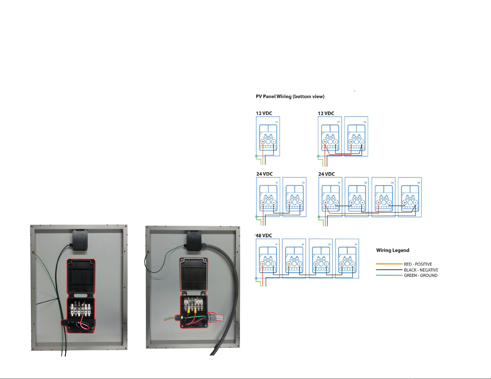
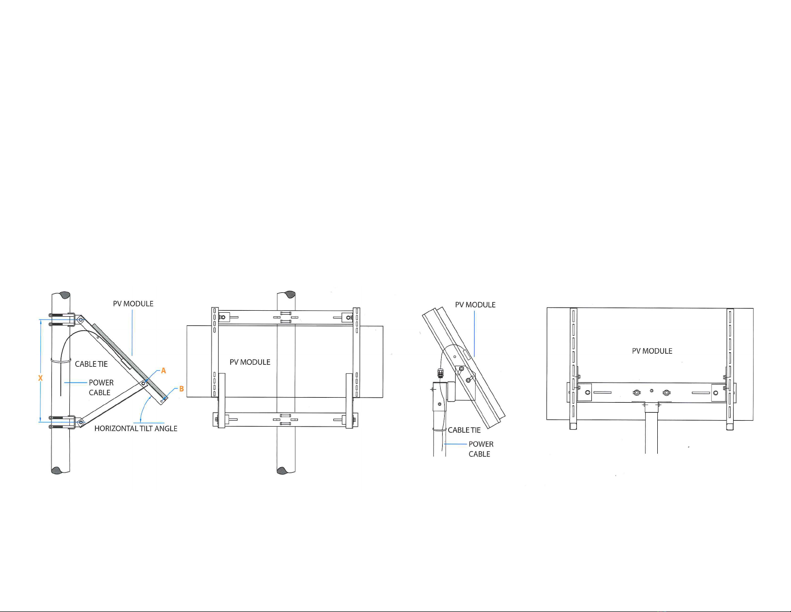
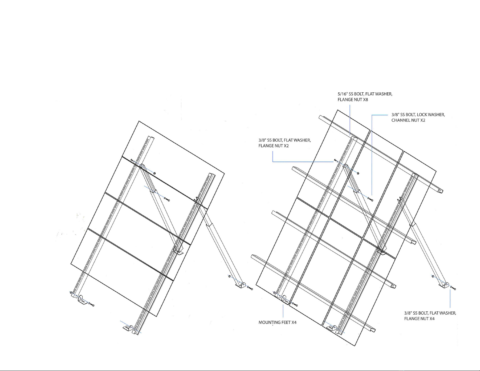
SunWize Power Ready Express User manual

The purpose of this guide is to assist you in setting up your
system quickly and eciently.
Quick Start
Sunwize Power Ready Express
Important! Prior to eld installation
Determine and ll in the information below. Refer to http://
www.ngdc.noaa.gov/geomag-web/#declination to determine
required information using site Lat./Long. or zip code. See
page 7 for detailed instructions.
Array tilt angle
Magnetic declination
See inside for list of required tools and additional materials.
For technical support call 866-827-6527Share your installation photo:
email to marketing@sunwizepower.com
Document # 310002

PV Modules
PV-Module mount
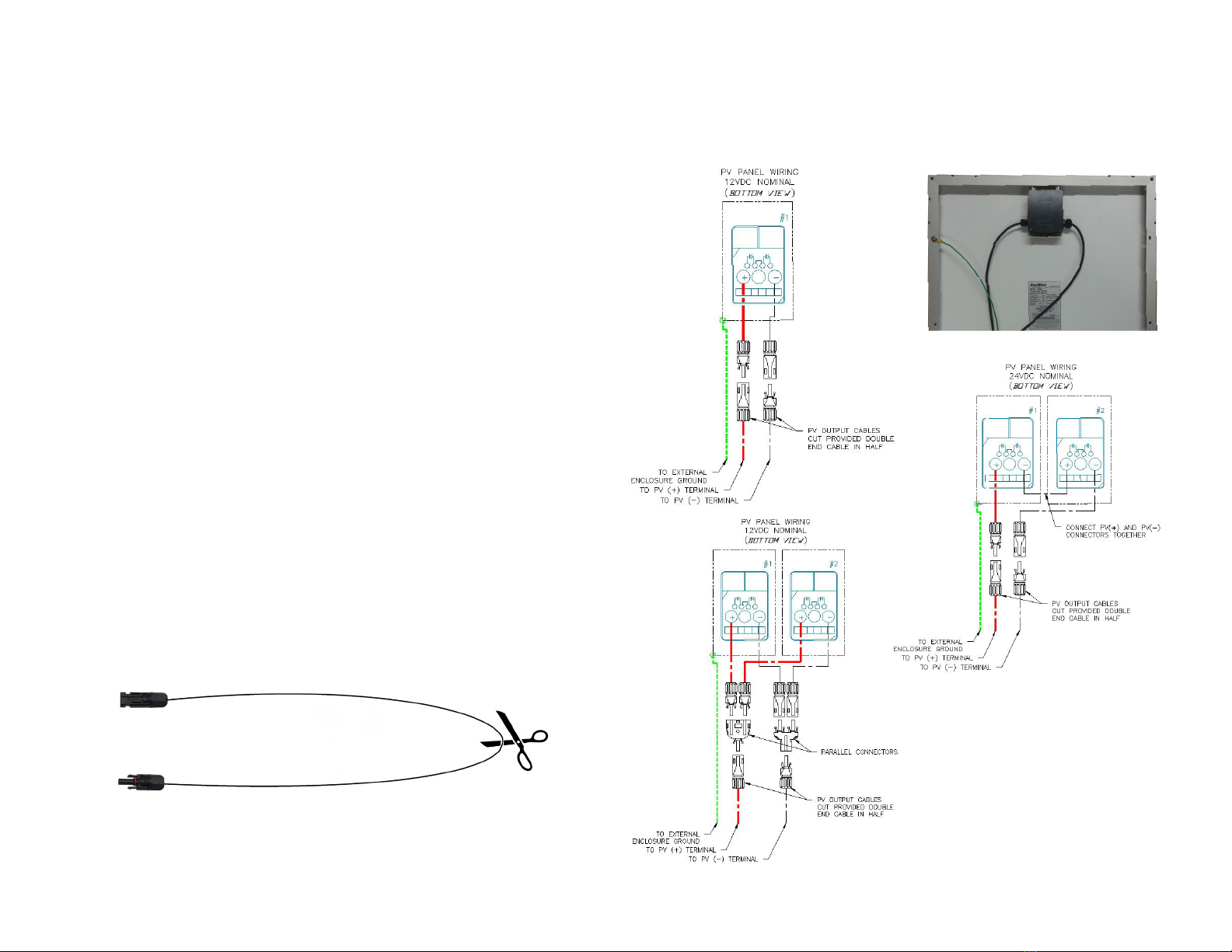
PV-Module output conductor kit
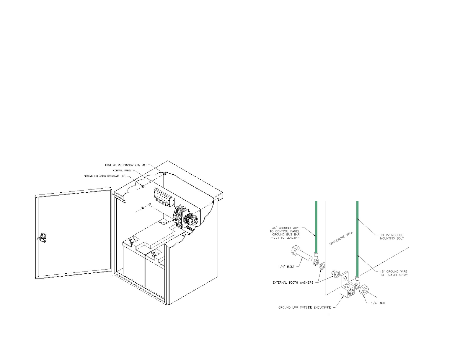
Enclosure
Enclosure mounting brackets (if required)
Batteries and battery cables
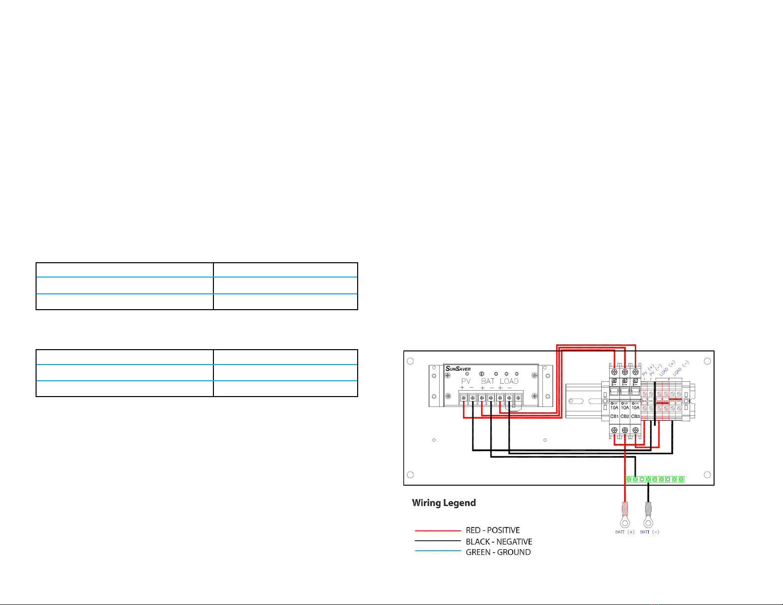
Control Panel
Installation Kit
(Optional) I/O Accessory Panel
System Parts List
You will need to supply these parts (not included):
Galvanized steel pole - 2”-8” sch 40 (if required)
Load wire - 18-6 AWG
Load conduit - 1/2” KO provided
Equipment grounding - 14-2 AWG lug provided, ground per local electrical code
Chest style only: Battery enclosure anchor bolts - 1/2” dia. (4 per enclosure)
Ground mounting only: Array mount anchor bolts - 1/2” dia. (4 per mount)
UV resistant cable ties
You will need these tools:
Wide, medium, and narrow at head and Phillips screwdrivers
Socket driver set and open end wrenches (3/8” - 3/4”)
5/32” Allen Wrench
3/16” Allen wrench
Magnetic compass
Tape measure
Grease pencil, chalk, scribe, or other marker
Digital multi-meter
Digital clamp on Amp meter (optional)
Photovoltaic (PV) modules generate electricity when exposed to light. Modules pose a
shock hazard and risk of serious injury or death if instructions and safety precautions are
not followed carefully. Cover the glass faces of the modules with opaque material while
working on the system to stop the production of electricity. Avoid touching the terminals
and isolate wire end until all connections are complete.
Batteries can explode or severely burn if the terminals are shorted to the opposite polar-
ity. A single point system ground is required per NEC A.690. It is recommended to tie the
battery negative (-) terminal to the equipment chassis at the time of installation. Always
observe proper polarities when making electrical connections to the modules, batteries,
and controller.

Side of Pole Mount
Attach top of array structure to pole at desired maximum height using supplied band
clamps or u-bolts per the manual provided with the mount.
Top of Pole Mount
Attach array with the gimbal to the top of the pole per the manual provided with the mount.
1aPV Array Installation: Pole Mount
Images for reference only

Ground Mount
1. Turn array to face South.
2. Assemble per the manual provided
with the mount.
1bPV Array Installation: Ground Mount
For Reference Only

Side of Pole Mount Enclosure
1. Mount upper mounting bracket at desired height of enclosure on the pole using U-bolts
or band clamps.
Ground Mounted Enclosure
1. Install the base mounting pads at the desired location using 1/2 inch concrete fastening
hardware. Refer to the chart for dimensions and the diagram for enclosure mounting hole
locations.
2. Check alignment and tighten bolts.
2Enclosure Installation
Install the lower mounting bracket, Spacing should be measured from the upper
bracket as follows:
Model Xinches/mm
WF2 or WF4 battery enclosure 23/584.2
F1 or F2 battery enclosure 12.7/327
F4 battery enclosure 24.1/612
F4 (tall) battery enclosure 39.1/993.14
2. Hang top of enclosure on top bracket - slip the tabs on either end of the mounting
bracket under the tabs on the top of the back of the enclosure.
3. Attached lower bracket to enclosure using the round carriage bolts.
M-series enclosure with
integrated mounting bracket

Side of Pole Mount Enclosure (Chest Enclosure Same)
1. Remove second set of supplied nuts from mounting studs located on the side wall of the enclosure
2. Adjust rst set of nuts on each stud to the same distance from enclosure wall leaving enough stud exposed for control panel and second nuts.
3. Install control panel and second set of nuts as shown below.
4. (Optional) If your system comes with an I/O panel, mount it to the side studs of the enclosure using the same procedure.
5. Verify all breakers are in the OFF (open) position.
6. Ground the control panel to the enclosure (see grounding below).
7. Install Batteries in enclosure (Do not connect wires yet).
3Control Panel Installation
Grounding
Set all circuit breakers in enclosure to OFF (open)
Install ground kit (provided) per gure below. Use wire rated for outdoor use per local
codes and size per NEC A.690 for system earth grounding. Verify system neutral bonding
is per local code.

PV Array Wiring with Quick Connectors
Set circuit breakers to OFF (open) and remove fuses in enclosure (if provided).
1. Route the output conductors from the PV panel to the enclosure. Secure the conductors
to the PV panel frame or the mounting surface using wire ties or other restraining hard-
ware (not provided). Install the cord grip tting to the rear of the enclosure using the 1/2
inch knock out provided.
2. Inside the enclosure, mate the PV array PV(+) conductor to the controller PV(+) termi-
nal block. Mate the BLACK PV(-) conductor to the controller PV(-) terminal block. Mate the
PV array GREEN GND conductor per instructions in grounding section.
3. For parallel connections use provided PV output parallel connectors (see gure right).
Note: If your system comes with a Combiner I/O Panel, see the wiring diagram included
with the combiner panel.
4Electrical Installation Single module with quick connectors
ground wire connects to mounting bolt at
module
Two modules with quick connectors and parallel
connectors
ground wire connects to mounting bolt at module
Two modules with quick connectors
ground wire connects to mounting bolt at
module
Quick Connector Cable Prep
Cut the Quick connector cable in two so both pieces can reach the appropriate module
quick connector and the appropriate termination point on the control panel or I/O panel.

4aElectrical Installation
PV Array Wiring with Tray Cable
Set circuit breakers to OFF (open) and remove fuses in enclosure (if provided).
1. Route the output conductors from the PV panel to the enclosure. Secure the conductors
to the PV panel frame or the mounting surface using wire ties or other restraining hard-
ware (not provided). Install the cord grip tting to the rear of the enclosure using the 1/2
inch knock out provided.
2. Inside the enclosure, mate the PV array PV(+) conductor to the controller PV(+) termi-
nal block. Mate the BLACK PV(-) conductor to the controller PV(-) terminal block. Mate the
PV array GREEN GND conductor per instructions in grounding section.
3. For all connections use correct interconnect cables and tray cable (see gure right).
Note: Congurations on the right are with 12V modules. For 24V modules the array volt-
age will be double the value shown for the conguration.
Tray Cable Conduit
For more than two strings, use a combiner I/O Panel and refer to
the diagram included with the panel for wiring instructuions.

Battery Wiring
For 12V systems
Each 12V battery is in parallel with the next. Connect the RED jumper from BAT 1 POSITIVE (+)
terminal to the BAT 2 POSITIVE (+) terminal and the BLK jumper from BAT 1 NEGATIVE (-) terminal
to the BAT 2 NEGATIVE (-) terminal. Repeat this pattern for each battery.
For 24V systems
Each pair of 12V batteries are in series and form one string. Connect the BLK jumper from BAT
1 NEGATIVE (-) terminal to the BAT 2 POSITIVE (+) terminal. Repeat this pattern for each series
string.
Each series string must be connected in parallel to complete the bank wiring. Connect the RED
jumper from BAT 1 POSITIVE (+) terminal to the BAT 3 POSITIVE (+) terminal, and the BLK jumper
from BAT 2 NEGATIVE (-) terminal to the BAT 4 NEGATIVE (-) terminal. Repeat this pattern foe each
parallel pair.
For 48V systems
Each quadruple set of 12V batteries are in series and form one string. Connect the BLK jumper from
BAT 1 NEGATIVE (-) terminal to the BAT 2 POSITIVE (+) terminal, BAT 2 NEGATIVE (-) terminal to
the BAT 3 POSITIVE (+) terminal, BAT 3 NEGATIVE (-) terminal to the BAT 4 POSITIVE (+) terminal.
Each series string must be connected in parallel to complete the bank wiring. Connect the RED
jumper from BAT 1 POSITIVE (+) terminal to the BAT 5 POSITIVE (+) terminal and the BLK jumper
from BAT 4 NEGATIVE (-) terminal to the BAT 8 NEGATIVE (-) terminal. Repeat this pattern for each
parallel pair.
Final Connection
Inside the control/battery enclosure, connect the controller RED BAT (+) wire to the battery bank
POSITIVE (+) terminal. Connect the controller BLK BAT (-) wire to the battery bank NEGATIVE (-)
terminal.
4bElectrical Installation
I/O Panels
For I/O Panel wiring, refer to the diagram provided with the panel.

Conrm all connections, ttings, and fasteners are secure and the PV array
surface is clean and facing South.
5Test the PV System
12V systems 21VDC (open circuit voltage)
24V systems 42VDC (open circuit voltage)
48V systems 84VDC (open circuit voltage)
Measure Voltages (Conrm all breakers are o before measuring)
Measure PV array voltage from the PV(+) terminal to the PV(-) terminal in the
enclosure.
Measure battery voltage from either the BAT(+) terminal block to the BAT(-)
terminal block or the BANK(+) to the BANK(-) to verify that they are approximately:
12V systems 12-13V
24V systems 24-26V
48V systems 48-52V
Set breakers to the ON (closed) position
On the charge control panel
1. Set the BAT(+) CB2 input breaker
2. Set PV(+) CB1 input breaker
3. Set the LOAD (+) CB3 output breaker
Conrm that the controller status LEDs function properly.
On the charge control panel, measure the voltage from the LOAD(+) ter-
minals to the LOAD(-) terminals which should be the same as the battery
voltage.
Verify both the PV and battery polarity is positive. If negative, reverse wiring
to the system and check again.

1. Turn the Power Ready System OFF.
A. Turn the PV breaker (CB1) OFF
B. Turn the Battery breaker (CB2) OFF
C. Turn the Load breaker (CB3) OFF
D. Connect your equipment to the terminal blocks on the control panel.
2. Turn the Power Ready System ON.
A. Turn the Battery breaker (CB2) ON
B. Turn the PV breaker (CB1) ON
C. Turn Load breaker (CB3) ON
D. Conrm the Power Ready System is providing power to the load.
6Connect Your Equipment

For optimum performance, your PV array should face true south in the Northern Hemisphere (and true north
in the Southern Hemisphere). However, when determining direction using a magnetic compass, indicated
bearings will vary from true bearings because of the dierence between the location of the true and magnetic
north poles. This angular dierence varies with location on the globe and is called the “declination.”
• Locate your using the web site below. (Great accuracy is not critical).
• Using the magnetic declination from the web site calculate true South. For example, the declination for
Washington, D.C., is
Approximately -11º; for Chicago, IL, -3º; and for Los Angeles, CA, +14º.
• Determine magnetic south at your site using a magnetic compass.
• If the local declination found in step 2 is negative, true south is that number of degrees added to
magnetic south. For example, at Washington, D.C., true south is the same as 180º + 11º = 191º
indicated. If the local declination found in step 2 is positive, true south is that number of degrees
subtracted from magnetic south. For example, at Los Angeles, true south is the same as 180º –
14º = 166º indicated.
• Orient your array in the direction of true south (or north if applicable) as determined above.
• The Internet site http://www.ngdc.noaa.gov/geomag-web/#declination will calculate magnetic variation from an input
of latitude and longitude, or Zip code.
For optimum performance, your PV array should set to a specic tilt angle. To determine the desired tilt angle
of the array, us the latitude from step one above.
Take this value and add the factor based on the table below. This will provide the optimum worst
case performance with the minimum amount of annual adjustment, based on the winter months
(Northern hemisphere).
Latitude range between 90 – 45° SET TO 60°
Latitude range between 40 – 25° +15°
Latitude range between 25 – 15° +5°
Latitude range between 10 – 0° SET TO 15°
7Calculate Installation Tilt and Azimuth
Table of contents