Sunwoda Atrix basic-5 Series User manual

User Manual
Atrix basic-5/10/15/20 Series
Residential energy storage systems
Version:V1.0


Content
1 Safety precaution ........................................................................................................................ 3
1.1 Storage and installation environment ........................................................................... 3
1.2 Battery safety guidelines ............................................................................................... 3
1.3 Warning signs and stickers ............................................................................................ 3
1.4 Emergency handling ...................................................................................................... 4
1 Product Description .................................................................................................................... 5
1.1 Product Introduction ..................................................................................................... 5
1.2 Product appearance description ................................................................................... 6
2 Installation Guide ........................................................................................................................ 7
2.1 Installation site requirements ....................................................................................... 7
2.1.1 Environmental requirements ............................................................................ 7
2.1.2 Physical installation requirements .................................................................... 8
2.1.3 Preparation of installation tools ...................................................................... 10
2.1.4 Unboxing guide ............................................................................................... 10
2.2 Installation steps ......................................................................................................... 11
2.2.1 Installation step ............................................................................................... 11
3 Electrical connection ................................................................................................................. 15
3.1 Grounding ................................................................................................................... 15
3.1.1 Connector installation ..................................................................................... 15
3.1.2 Guide of electrical connection ........................................................................ 17
4 System commissioning .............................................................................................................. 23
4.1 System power on ......................................................................................................... 23
4.2 System power off ........................................................................................................ 24
4.3 System configuration ................................................................................................... 24
5 Maintenance and troubleshooting ........................................................................................... 27
5.1 Routine maintenance .................................................................................................. 27
5.2 Fault checklist .............................................................................................................. 27
6 Warehouse storage guidelines .................................................................................................. 28
6.1 Packaging guidelines ................................................................................................... 28
6.2 Storage ........................................................................................................................ 29
7 Dispose of used batteries .......................................................................................................... 29
8 Detailed parameter ................................................................................................................... 30

3
1 Safety precaution
Read the manual carefully and operate in accordance with the safety precautions. Refer to local
safety regulations on items not covered in this manual. Electrical installation, maintenance must
be performed by professional / qualified personnel.
1.1 Storage and installation environment
Handle the product gently, prevent from dropping
Avoid open flame; keep away from flammables, explosives or corrosive chemicals
Choose cool and dry place for storage and installation
Prevent from water or humid intrusion
Prevent from accidental access (children and animals)
Do not step on the product packaging
Do not place any foreign objects on top of the battery pack
Do not store the battery pack upside down
1.2 Battery safety guidelines
Prevent from electrostatic discharge
Wear insulating gloves when handling batteries.
Do not energize auxiliary power during installation
Check the polarity carefully before switching on the system
Defected or damaged batteries shall not be charged or discharged
Use the product only with inverters authorized by Sunwoda Energy, or consult
Sunwoda Energy's product engineers. For compatible list inverters, please visit:
https://www.sunwodaenergy.com/download.
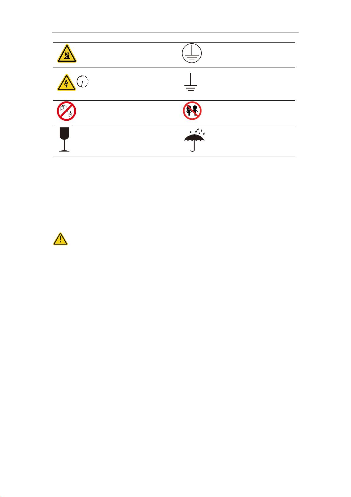
1.3 Warning signs and stickers
Warning generic hazard
DO not mix with domestic
Warning
High Voltage -
Electrical shock hazard Please recycle
No flame
This side up
No stepping on
User manual
4
Warning
High temperature
Protective Earth
(connector)
Warning
High Voltage
Wait 5 min till fully discharged
Protective Earth
(general identification)
Do not short circuit
(cut off power)
Keep away from children
Fragile
Do not get wet
1.4 Emergency handling
Wear personal protective equipment (PPE) such as goggle, facemask, insulated gloves and boots.
Evaluate the situation before taking remedy action. When it is safe to do so, disconnect external
AC or DC power connection.
Damaged or deformed battery enclosure
Risk of chemical leakage (i.e. electrolyte) and internal short-circuit.
Warning
Deformed or severely damaged battery pack can lead to piercing of cell pouch (chemical leakage)
or internal short-circuit (thermal runaway). The damaged battery pack can release toxic gas. Keep
away from it.
In case of accidental skin contact, wash the skin thoroughly with soap and seek medical advice. For
eye contact, wash under running water (~15 minutes) and require immediate medical attention.
Fire hazard
If the fire is not from the battery or not spread to the battery, use FM-200 or CO2 fire extinguisher
to put out the fire.
If the battery pack catches fire, do not attempt to put out the fire and evacuate immediately.
Seek medical in case of inhalation of pungent and toxic fumes.
Keep damaged batteries isolated and call your local fire department. Contact service for further
support.
Note:
1. If a fire occurs during battery charging, disconnect the battery pack circuit breaker and cut off
the power supply for charging under safe conditions.
2. If the battery string does not catch fire, extinguish the fire before the battery string catches fire.
3. If the battery pack catches fire, do not attempt to extinguish the fire. Evacuate immediately.
5 m in

5
Water damage
Risk of electric shock and internal short-circuit. In case of splash or water spillage, when it is safe
to do so, dry the product. If any part of the battery system is submerged, keep away from water.
Do not reuse the submerged battery. Contact a service for support.
1 Product Description
This document mainly introduces the product, installation, commissioning, maintenance,
troubleshooting, packaging, and transportation of the Atrix basic energy storage system.
1.1 Product Introduction
• This product is a lithium battery energy storage system based on the chemical composition of
Lithium Iron Phosphate (LFP), and adopts a module parallel design.
• A single system consists of a data display box (optional) and multiple battery modules, and
supports up to 4 battery modules in parallel.
• The battery energy storage system can be used with the inverter, and the communication adopts
CAN .
• The system supports up to 2 single systems connected in parallel, which can be expanded to
40kWh.
• The battery management system provides data collection, status monitoring and control to
ensure safe and reliable operation of the system.
• The system adopts IP20 protection design to support indoor use.
System Diagram
WiFi
Internet
GPRS
APP
APP
Products within the dotted line are provided by SUNWODA ENERGY
DC Power cable
Signal cable
Wireliss communication
Atrix
basic
Optional
6
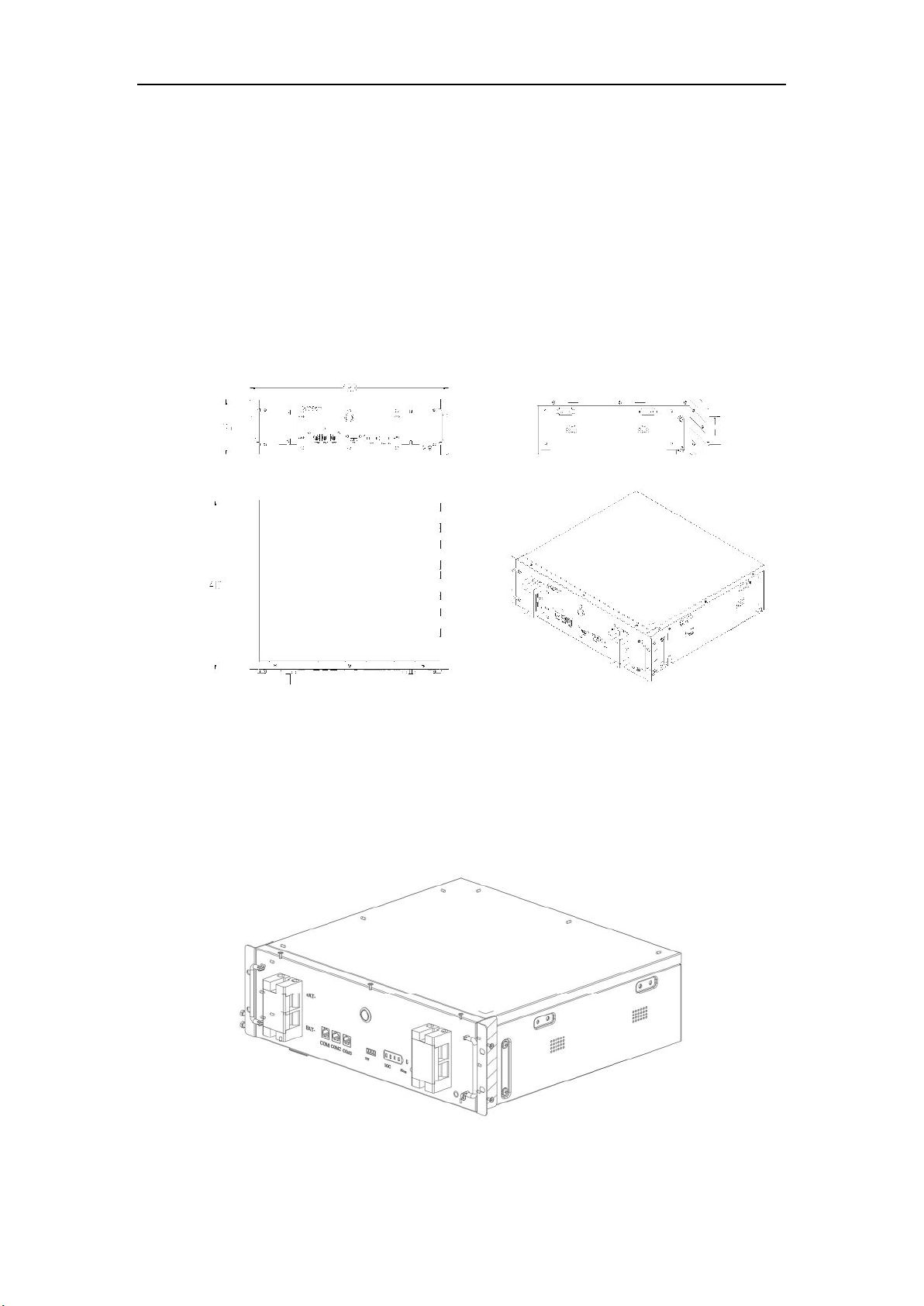
1.2 Product appearance description
Product size chart:
The battery module size diagram and effect diagram are shown in the following figure:
Size: W*D*H=443*410*135 mm
Weight: 45kg
Dimensions of module
7
Battery module diagram
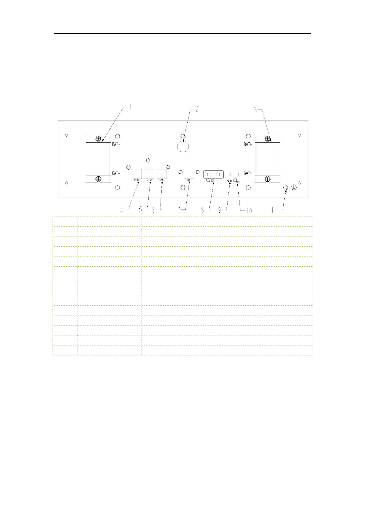
Product Front Panel Definition:
NO Item Function Note
1 .BAT- Battery output negative interface
2 POWER Battery module switch button
3 BAT+ Battery output positive interface
4 COM1 Communication interface with PCS CAN
5 COM2 Automatic addressing and internal CAN
communication interface
6 COM3 Automatic addressing and internal CAN
communication interface
7 SW One-key open interface
8 SOC Battery module SOC indicator LED light
9 Alarm Battery module fault LED light
10 Run Battery module running LED light
11 PE Battery module ground hole
2 Installation Guide
2.1 Installation site requirements
2.1.1 Environmental requirements
a. Ambient temperature: -10℃~+50℃ (recommended: 10℃~35℃ or 50℉~95℉).
b. Ambient humidity: 10-95%.
c. Altitude <= 4000 meters.
d. For indoor installation
• Avoid direct sunlight

8
• Avoid rain and snow
• Avoid flood-prone locations
• Install under shed if possible
• 3 feet of clearance from doors, windows, driveways, or other batteries
• Keep away from heating equipment.
• Protection against corrosive chemicals
• Prevent water from spilling
e. Consider locations with ventilation fans, smoke, heat or combustible gas detectors.
Warning!
Use of Atrix basic outside of the temperature range may cause irreversible damage to it
Note: If Atrix basic is used below 10 degrees or above 40 degrees, the charging and discharging
current of Atrix basic may decrease.
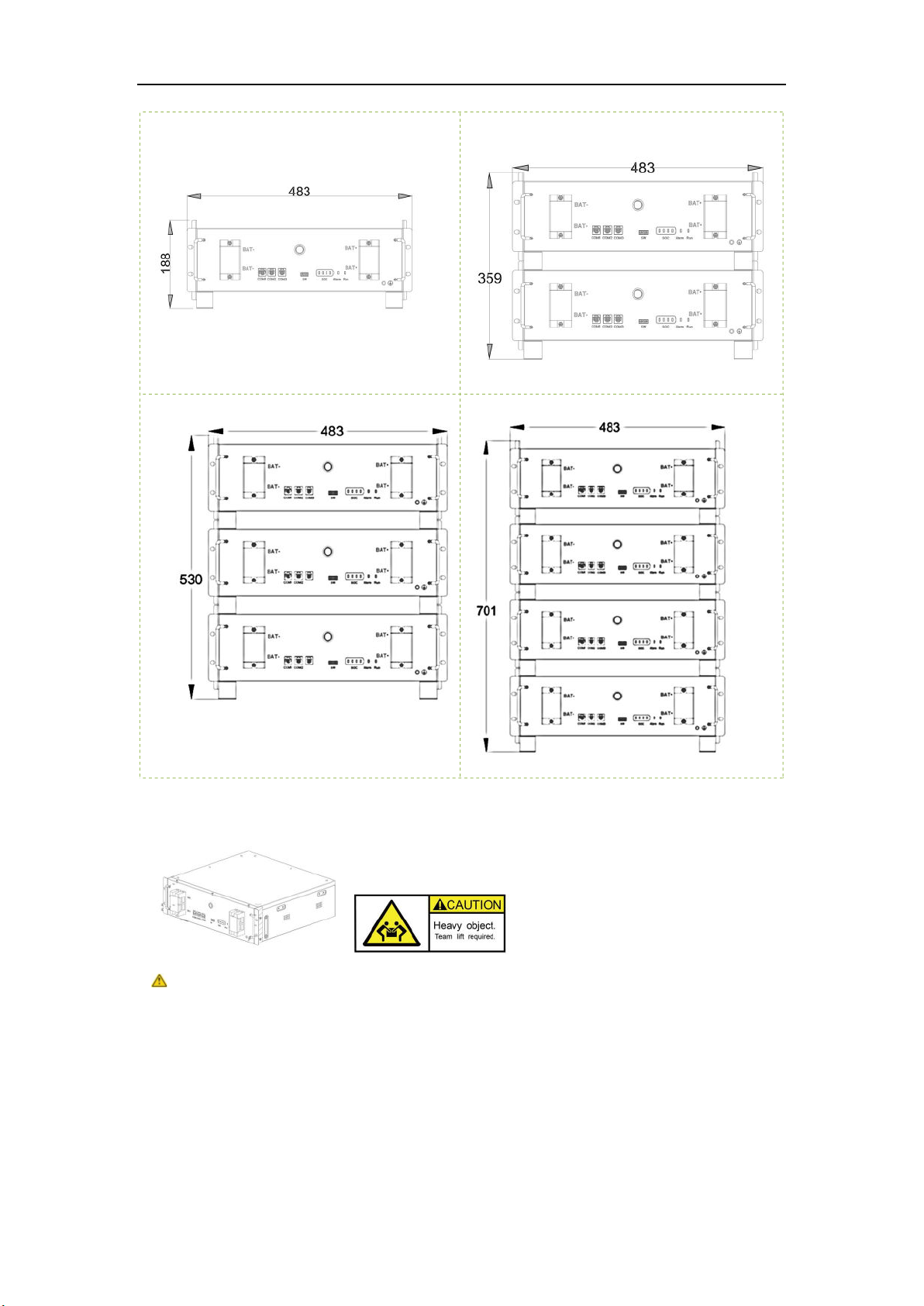
2.1.2 Physical installation requirements
This simple bracket is optional. Assuming that the client has a cabinet or bracket designed to meet
the standard 19inch and 3U height installation, it is not necessary to choose this suggestion and
ignore the following installation methods.
a. Product installation dimensions
BATT
Indoor
BATT
Outdoor
9
Atrix basic-5:
Atrix basic-10:
Atrix basic-15:
Atrix basic-20:
b. Weight
45kg (99.2lbs)
For 2 persons
This manual suits for next models
3
Table of contents
Other Sunwoda Batteries Pack manuals


Popular Batteries Pack manuals by other brands


IOGear
IOGear GBP24V Series user manual

Inventus Power
Inventus Power PROTRXion S-12V100-TRX-HD user manual

Clas Ohlson
Clas Ohlson PW-290A quick start guide

EINHELL
EINHELL MULTI-Ah Power X-Change Plus Original operating instructions

Samsung
Samsung EB-U3300 quick start guide

ECTIVE
ECTIVE LC Series instruction manual