VEGA POWER Power Cell PCW050050N Manual

MODEL : PCW050050N
V-2

HANDLING GUIDE
SAFETY INSTRUCTIONS
INTRODUCTION
SPECIFICATIONS
DEVICE
OVERVIEW
COMPONENTS
INSTALLATION
MULTIPLE CELL CONNECTION
DEVICE SETUP
PRODUCT APPLICATION
WARRANTY DISCLAIMER
02
04
07
08
09
12
13
14
17
18
21
24

STORAGE
Place battery according to signs on packing case. Do not put battery upside down or sidelong.
Store batteries in a place free from direct sunlight and rain.
Keep batteries at least two meters away from a heat source (such as a radiator).
Avoid contacting with corrosive and organic substances (including gas exposure).
Batteries with deficiencies should be separated from normal batteries by setting wall between or
placing in difference fire protection zones.
Ambient temperature ranges between 20°C to 45°C. Relative humidity ranges between 10%
RH-70% RH.
Keep the storage area dry, clean and well ventilated.
In case of storage over six months, batteries should be recharged in the following steps.
TRANSPORTATION
Before transportation, press POWER button for two seconds and five LED lights flicker for three
times to power off battery.
During transportation, put battery flat or stand position, do not lean on the floor to avoid
possible crash.
Maintain temperature between 20°C to 45°C during the transportation.
Prohibit mixing up with explosive, inflammable or toxic objects.
Use van-type vehicle including container and metallic van-type vehicle.
Do not pile up foreign objects on the top of battery. Four batteries at most can be piled up.
Maintain original packaging and keep labels complete and recognizable.
Prevent from direct sun exposure, rain, condensation and mechanical damages.
POWER CELL HANDLING GUIDE
Identify batteries that need recharging;
Ensure batteries in power-off mode. Refer to Quick Guidance to complete the installation and
wire connection;
Set “CV=55V,CC=50A” and start recharging;
Recharge until LED2 flicks;
Leave circuit open and rest battery for five minutes. Check battery voltage. If voltage is not
less than 52 V, the recharging succeeds;
1.
2.
3.
4.
5.

POWER CELL HANDLING GUIDE
BEFORE CONNECTING
Do not put battery upside down or sidelong.
After unpacking, please check product and packing list first, if product is damaged or lack of
parts, please contact with the local retailer.
Before installation, be sure to cut off the grid power and make sure the battery is in the
turned-off mode.
Wiring must be correct, do not mistake the positive and negative cables, and ensure no
short circuit with the external device.
It is prohibited to connect the battery with AC power directly.
The embedded BMS in the battery is designed for 48VDC, please DO NOT connect battery in
series.
It is prohibited to connect the battery with different type of battery.
Please ensure the electrical parameters of battery system are compatible to inverter.
Battery system must be well grounded and the resistance must be less than 1 ohms.
Please ensured the electrical parameters of battery system are compatible to related
Equipment (Inverter).
Keep the battery away from water and fire.
DURING OPERATION
If the battery system needs to be moved or repaired, the power must be cut off and the battery
is completely shut-down.
It is prohibited to connect the battery with different type of battery.
It is prohibited to put the batteries working with faulty or incompatible inverter.
It is prohibited to disassemble the battery (QC tab removed or damaged).
In case of fire, only dry powder fire extinguisher can be used, liquid fire extinguishers are
prohibited.
Please do not open, repair or disassemble the battery except staffs from Pylontech or authorized
by Manufacturer. We do not undertake any consequences or related responsibility which
because of violation of safety operation or violating of design, production and equipment safety
standards.

SAFETY PRECAUTIONS
It is very important and necessary to read the user manual carefully (in the accessories) before
installing or using battery. Failure to do so or to follow any of the instructions or warnings in this
document can result in electrical shock, serious injury, or death, or can damage battery,
potentially rendering it inoperable.
If the battery is stored for long time, it is required to charge them every six months, and the SOC
should be no less than 90%.
Battery needs to be recharged within 12 hours, after fully discharged.
Do not expose cable outside.
All the battery terminals must be disconnected for maintenance.
Please contact the supplier within 24 hours if there is something abnormal.
Do not use cleaning solvents to clean battery.
Do not expose battery to flammable or harsh chemicals or vapors.
Do not paint any part of battery, include any internal or external components.
Do not connect battery with PV solar wiring directly.
The warranty claims are excluded for direct or indirect damage due to items above.
Any foreign object is prohibited to insert into any part of battery.
RISKS OF FIRE
Do not expose battery to direct sunlight.
Avoid contact with conductive objects such as wires.
Keep battery away from fire source, inflammable, explosive and chemical materials.
Do not dispose of batteries in a fire. The batteries may explode.
RISKS OF ELECTRIC SHOCK
Do not touch battery with wet hands.
Keep battery away from children and animals.
A battery can present a risk of electric shock and burns by high short-circuited current.
Battery installation and wire connection must be operated by professionals.

RESPONSES TO EMERGENCIES
RISKS OF DAMAGE
Keep distance to water source.
Do not subject battery to high voltage.
Place battery on a flat surface.
Do not place any foreign object on top of the battery nor step on the battery.
Battery-connected PCS should have reinforced insulation.
WET BATTERIES
If battery became wet or has been submerged in water, do not access it. Immediately contact the
manufacturer for technical assistance. Do not dispose of batteries in a fire. The batteries may
explode.
LEAKING BATTERIES
If the battery pack leaks electrolyte, avoid contact with the leaking liquid or gas. Electrolyte is
corrosive and contact may cause skin irritation and chemical burns.
Evacuate the
contaminated area,
and seek medical
attention immediately.
Rinse eyes with flowing
water for 15 minutes, and
seek medical attention
immediately.
Induce vomiting, and
seek medical attention
immediately.
Wash the affected area
thoroughly with soap and
water, and seek medical
attention immediately
Inhalation Eye contact Swallow Skin contact

RESPONSES TO EMERGENCIES
FIRE
In case of fire, only dry powder fire extinguisher can be used, liquid fire extinguishers are
prohibited. Battery may catch fire when heated above 150°C. Please implement the following
actions.
Extinguish fire before the battery catches fire. ABC or carbon dioxide extinguisher is
recommended.
If the fire is too strong to put out, move battery to a safe place before it catches fire.
If battery is on fire, evacuate people first before seeking help from professional fire protection
personnel.
If battery catches fire during charging, turn off the breaker between battery and power
conversion system when safety can be guaranteed.
If the battery catches fire, it will produce noxious and poisonous gases. Do not approach.
QUALIFIED INSTALLER
This manual and the tasks and procedures described herein are intended for the use of skilled
workers only. A skilled worker is defined as a trained and qualified electrician or installer who has
all of the following skills and experience.
Knowledge of the functional principles and operation of on-grid/ off-grip systems.
Knowledge of the dangers and risks associated with installing and using electrical devices and
acceptable mitigation methods.
Knowledge of the installation of electrical devices.
Knowledge to adherence to this manual and all safety precautions and best practices.

INTRODUCTION
INTRODUCTION
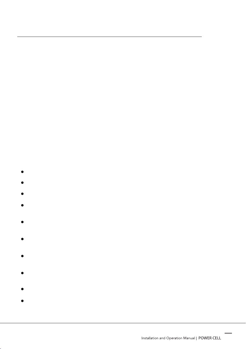
POWER CELL, lithium iron phosphate battery pack is a household renewable energy
storage solution designed and developed by Vega Innovations Pvt Ltd, Sri Lanka. It is a
low-voltage DC battery pack with an nominal voltage of 51.2 V and maximum capacity
of 5 kWh. Which operates with hybrid and off-grid 48 V inverters to facilitate energy
storage requirements of home and solar applications.
POWER CELL integrate seamlessly with your modern home with wall mountable
enclosure. For ease of installation, it comes with quick disconnecting sockets to ease the
process of integration.
POWER CELL supports parallel connection to expand capacity, which can meet various
capacity requirements up to 80 kWh. It has a built-in smart battery management system
(BMS), which can monitor and manage battery pack conditions including voltage, current
and temperature. Furthermore it’s equipped with battery cell balancing capability to
optimize the capacity and an interface to communicate with the inverter.
FEATURES
Compatible with established 48V inverters both hybrid and off-grid in the market.
Minimalist enclosure design to seamlessly blend with your modern home.
Brand new grade A battery cells with 3.2V of voltage and 100 Ah of capacity.
Battery cells has the lithium iron phosphate (LFP) chemistry offering longer cycle life
and safety performance.
Battery cells are assembled with cell protecting insulation/cushioning materials that
can facilitate proper insulation and expansion while charging and discharging.
Battery cells are in contact with the enclosure through thermal transfer material to
remove excessive heat.
In-built battery management system with cell monitoring capabilities to ensure a
stable and safe flow of power to you home.
LCD screen that offers real time voltage, temperature, current and status
information of cell and pack level.
Expansion capability up to 80 kWh by connecting 16 battery packs in parallel.
Short circuit protection and manual disconnecting capability through the MCB.
07

BASIC SPECIFICATIONS AT 250C
* To prolong the battery life time. (15% - 90% SOC) ** Please refer the chart
08

09

POWER / RESET
BATTERY V+ (RED)
BATTERY V+ (RED)
DIP SWITCH
RS485 PORT
RS485 PORT
CAN PORT
SOC INDICATORS
Alarm INDICATORS
10

[-] BATTERY TERMINAL (BLACK)
[-] BATTERY TERMINAL (BLACK)
PRESSURE RELEASE VALVE
EARTH POINT
MCB
11

[ W - Wall mount | R - Rack mount ]
[ W - Wall mount | R - Rack mount ]
12
OVERVIEW

13

INSTALLATION
REQUIRED TOOLS FOR INSTALLATION
INSTALLATION LOCATION
14
If the ambient temperature is outside the operating range, the battery pack stops operating to
protect itself. The optimal temperature range for the battery pack to operate is 20°C to 45°C.
Frequent exposure to harsh temperatures may deteriorate the performance and life of the
battery pack.
Safety Shoes
Multimeter
Screw driver Wire stripper Crimper Hammer drill
Tape measure Pencil Cable wrench
Safety Goggles Insulated Gloves Hydraulic plier
Make sure that the installation location meets the following conditions:
The installation site must be suitable for the size and weight of the battery.
Must be installed on a firm surface to sustain the weight of battery.
The area is water proof and free from conductive dust and corrosive gas.
There are no flammable or explosive materials in proximity.
The ambient temperature is within the range from 20°C to 45°C.
The temperature and humidity is maintained at a constant recommended level. Do not install
battery in highly humid area such as bathroom.
There is minimal dust and dirt in the area.
Ensure direct contact between battery shell and ambient air. Do not cover or shield battery to
avoid poor cooling.

INSTALLATION
15
WALL
1
1POWER CELL
UP BRACKET
DOWN BRACKET
BOLT
ANCHOR BOLT
WALL BRACKET
2
3
4
5
6
2
3
4
5
6
In order to avoid electrical shock or other injury, inspect existing electronic or plumbing
installations before drilling holes. The battery is heavy, please handle with care to avoid damage
to the product or injury to the installer.
Falling equipment can cause serious or even fatal injury: never mount the Power Cell on the
bracket unless you are sure that the wall bracket is firmly mounted on the wall after thorough
checking.

INSTALLATION STEPS
INSTALLATION
16
Choose suitable firm wall (Concrete/ Brick) with thickness greater than 150 mm
Drill 6 holes on the wall according to Power Cell mounting template (Included in the box).
Secure Anchor bolts (Included in the box) with a hammer in to holes properly. Do not position
screws flush to the wall - leave 10 to 15 mm exposed.
Place the wall mount with the right orientation as shown in the Power Cell mounting template
and secure it with nuts given with anchor bolts.
Secure UP and DOWN battery mounts with bolts (Included in the box).
Hang battery mounts assembled Power Cell on the Wall mount properly.
Connect earth cable to the earth point.
Having confirmed fixed installation, plug power cables into battery terminals (red positive
terminal and black negative terminal).
Plug CAN network cable into the network ports of power conversion system and battery.
Please refer Device Setup page.
Note: Some power conversion systems doesn’t have built in CAN communication. In such a
situation, Please ignore the above step.
If you are connecting multiple batteries, plug RS485 network cables into the relevant network
ports (RS485). Please refer Device setup page.
PRE-INSTALLATION CHECKS
Check exterior package: before opening package, check for damages like holes, cracks or
other traces on exterior packing case. If any abnormality is detected, do not open the package
and contact your distributor.
Check deliverables: after opening package, check if deliverables are complete. If there is any
part missing or damaged, please contact your distributor.
Check and confirm the battery is powered off and breaker is open before any further step.

MULTIPLE POWER CELL CONNECTION
[+] BUS BAR[-] BUS BAR
JUNCTION BOX
CONFIGURATION TYPE 01
CONFIGURATION TYPE 02
17
Following configurations can be followed to connect two or more Power Cells with your
inverter setup for capacity expansion. You can expand the capacity of the battery bank up to
80 kWh by connecting 16 Power Cell in parallel. If the maximum battery power input of your
inverter setup is more than 6 kWh, It is recommended to follow the configuration type 01.
Otherwise configuration type 02 is recommended.

DEVICE SETUP
RS485 PORT
RJ45CABLE
RS485 PORT
RS485 NETWORK CABLE RS485 NETWORK CABLE
CAN PORT
CAN NETWORK CABLE
18
After connecting power cables to
the battery from power
conversion system, CAN network
cable and RS485 network cables
have to be connected as above.
Some power conversion systems
doesn’t have built in CAN
communication. In such a
situation, no need to connect a
CAN network cable from the
power conversion system to the
battery.
POWERCELL that you are
connecting to the inverter
through a RJ45 cable to its CAN
port is defined as the master
pack. Rest of the packs are
defined as slave packs.
To set up RS485 communication
dip switches have to be
configured according to FIG 1.0.

DEVICE SETUP
INDICATOR LIGHTS
There are 6 lights to indicate several operating status of the Power Cell. First 4 lights indicate the SOC
level according to the table bellow.
5th light is the alarm indication. If it is blinking in red colour, there is a warning which can be checked
through the LCD screen. If it stays in red colour, battery pack is in a state of abnormal temperature,
over current or short circuit.
6th light is the battery turn-on status indication. It may stay illuminated or blink in green colour.
19
Table of contents
Other VEGA POWER Batteries Pack manuals