User Manual
1
1Safety instruction
Before transportation, storage, installation, operation, use, or maintenance of equipment, please
carefully read and properly store this manual and strictly follow the safety precautions required by
the manual content for operation. The safety precautions mentioned in this manual are only a
supplement to local safety regulations.
The "danger", "warning", "caution", and "instructions" in the manual do not represent all safety
precautions that should be followed. You are also required to comply with relevant international,
national, or regional standards, as well as industry practices. Our company does not assume any
responsibility for violating safety operation requirements or violating safety standards for the design,
production, and use of equipment.
The equipment shall be used in an environment that meets the requirements of the design
specification; otherwise, equipment failure, equipment function abnormality, or component damage
may be caused, which is not within the scope of equipment quality assurance. Otherwise, our
company shall not be liable for compensation for potential personal injury, property damage, etc.
All operations, such as transportation, storage, installation, operation, use, and maintenance,
should comply with applicable laws, regulations, standards, and normative requirements. It is not
allowed to study the internal implementation logic of the device in any way, obtain the source code
of the device software, infringe intellectual property rights, or to disclose the results of any device
software performance testing.
Our company shall not be liable for any of the following situations or their consequences:
● Equipment damage caused by earthquake, flood, volcanic eruption, debris flow, lightning strike,
fire, war, armed conflict, typhoon, hurricane, tornado, extreme weather, force majeure,
● Not operating within the usage conditions specified in this manual,
● The installation and usage environment do not comply with relevant international, national, or
regional standards,
● Failure to follow the operating instructions and safety warnings in the product and documentation;
● Unauthorized disassembly, modification of products, or modification of software codes;
● The materials and tools you provide do not meet the requirements of local laws, regulations, and
relevant standards.
● Damage caused by negligence, intent, gross negligence, improper operation, or non-company
reasons by you or a third party.
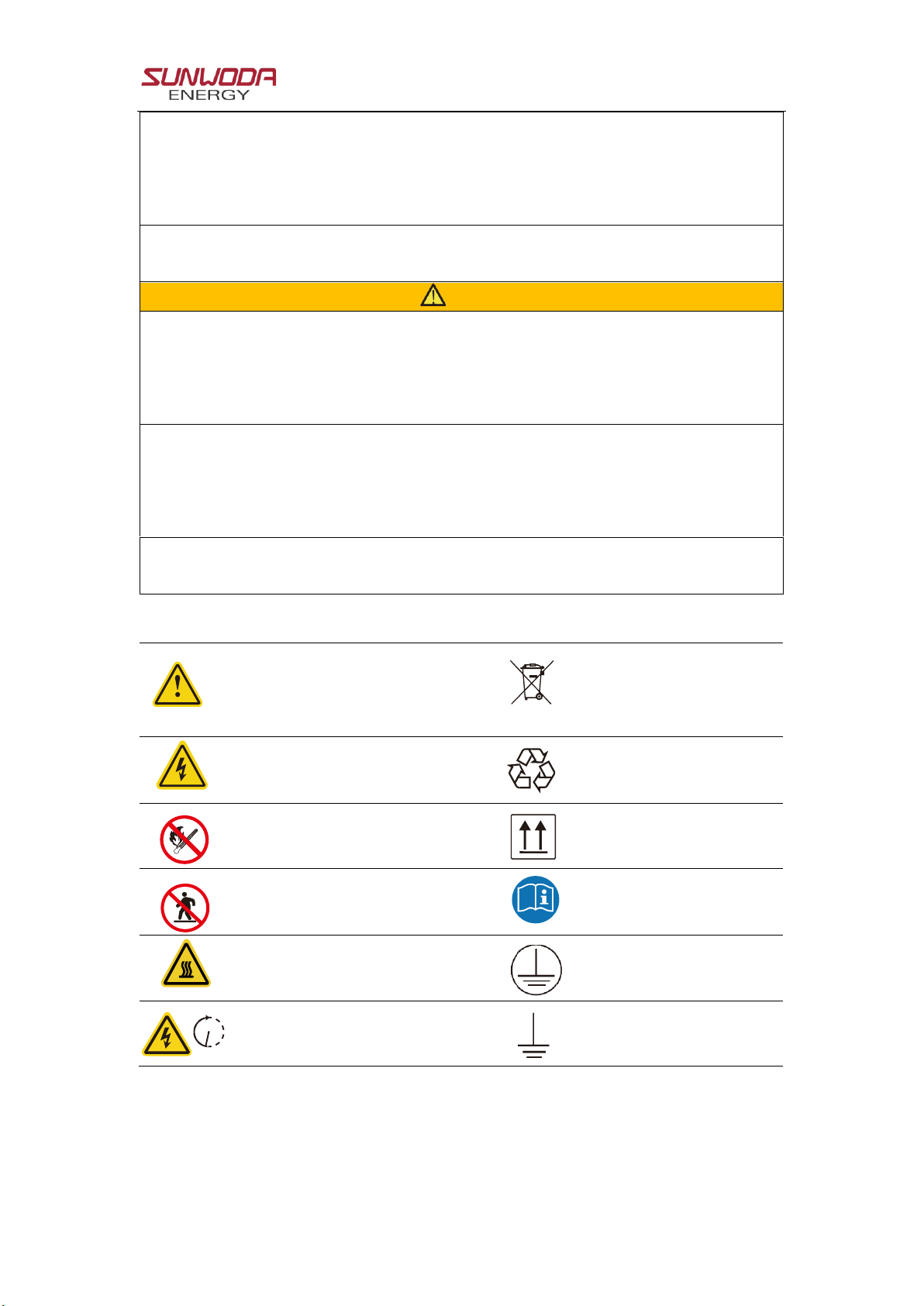
1.1 Safety precaution
1.1.1 Personal safety