Super 15.11 AR User manual

IDROPULITRICI AD ALTA PRESSIONE
HIGH PRESSURE WATER CLEANERS
MANUALE D’USO E MANUTENZIONE
INSTRUCTIONS MANUAL
SUPER
Ed. 05/01

QUADRO COMANDI
CONTROL BOARD
2
SUPER
1INTERRUTTORE MAGNETO-TERMICO, IG
MAGNETO-THERMAL SWITCH, IG
2MANOMETRO
MANOMETER
3INTERRUTTORE BRUCIATORE, IB
BURNER SWITCH, IB
4MANOPOLA DI REGOLAZIONE TERMOSTATO, TR
THERMOSTAT SETTING KNOB, TR
5RUBINETTO DETERGENTE (solo modelli IP)
DETERGENT TAP (IP model only)
6SPIA MANCANZA ACQUA (solo modelli Fermo-macchina)
LACK OF WATER WARNING LIGHT (Total Stop model only)
7SPIA MANCANZA DETERGENTE (solo modelli Fermo-macchina)
LACK OF DETERGENT WARNING LIGHT (Total Stop model only)
8SPIA MANCANZA GASOLIO (solo modelli Fermo-macchina)
LACK OF GASOIL WARNING LIGHT (Total Stop model only)
70
30
50
90
I
0
C
0
I
H2O
1
2
54 3
8
6
7
COSTRUTTORE BIEMMEDUE S.p.A.
MANUFACTURER Via Industria, 12
12062 Cherasco (CN) - ITALIA
Tel. 0172 / 48.61.11 - Fax 0172 / 48.82.70
MODELLI SUPER 15.11 AR, SUPER 15.15 AR, SUPER 20.15 AR, SUPER 15.15 IP, SUPER 15.21 IP,
MODEL SUPER 20.15 IP, SUPER 150 IP, SUPER 150S IP, SUPER 200 IP
Prima di usare il generatore, si prega di leggere con attenzione tutte le istruzioni d’uso riportate di seguito e di seguirne scrupolosamente le indicazioni.
Il costruttore non è responsabile per danni a cose e/o persone derivanti da uso improprio dell’apparecchio.
Before using the water cleaner, read and understand all instructions and follow them carefully.
The manufacturer is not responsible for damages to goods or persons due to improper use of units.
Ed. 05/01

DESCRIZIONE
Le idropulitrici della serie SUPER sono macchine professionali per
la pulizia e il lavaggio con acqua ad alta pressione e alta temperatura.
L’acqua è sospinta dalla pompa ad alta pressione, pompa A.P., at-
traverso il circuito idraulico sino alla serpentina di riscaldamento dove
un bruciatore alimentato a gasolio produce il calore necessario a riscal-
darla. Dosi regolabili del detergente contenuto nell’apposito serbatoio
possono essere miscelate all’acqua e vengono erogate con acqua in al-
ta pressione per i modelli IP e con acqua in bassa pressione per i mo-
delli AR. Manovrando la lancia e premendo la leva dell’impugnatura au-
tomatica, l’operatore dirige il getto d’acqua verso la superficie da pulire
o da sgrassare. Se durante l’operazione di lavaggio si rilascia la leva
dell’impugnatura automatica, il getto d’acqua si interrompe immediata-
mente, il bruciatore si spegne e la pompa A.P. ricircola l’acqua con mo-
dalità che dipende dal modello, Bypass, B.P., o Fermo-Macchina, F.M.
(si vedano le istruzioni del paragrafo “Interruzione del lavaggio”).
La versione F.M. è equipaggiata con un’apparecchiatura elettronica
per il controllo automatico delle operazioni di avviamento e spegnimen-
to della pompa A.P. e del bruciatore; tre spie di controllo segnalano
tempestivamente l’eventuale mancanza di gasolio, acqua o detergente
(si veda il paragrafo “Spie di segnalazione”).
Attenzione
Le principali caratteristiche tecniche dell’idropulitrice
che avete acquistato sono riportate in una etichetta ade-
siva posta sulla parete laterale del quadro elettrico.
RACCOMANDAZIONI GENERALI
Si raccomanda di:
• leggere con attenzione le istruzioni contenute nel presente ma-
nuale e seguirle scrupolosamente;
• non depositare materiali facilmente infiammabili nelle vicinanze
dell'apparecchio (la distanza minima deve essere pari a 3 m);
• utilizzare l’idropulitrice all’aperto o in un locale ben ventilato di-
sponendola nelle vicinanze di un quadro elettrico con caratteristiche di
alimentazione elettrica conformi a quelle dichiarate;
• non usare cavi elettrici di prolunga;
• non rivolgere il getto d’acqua verso l’idropulitrice o verso qualsia-
si altra parte in tensione elettrica;
• non utilizzare acque sporche o sabbiose, nè prodotti chimici cor-
rosivi o infiammabili
• non rivolgere il getto d’acqua verso persone o animali, nè verso
parti alimentate elettricamente;
• controllare l’apparecchio prima della messa in funzione e sorve-
gliarlo regolarmente durante l'uso impedendo l'avvicinamento di bam-
bini e/o animali;
• disinserire l’interruttore di sezionamento al termine di ogni eser-
cizio d'uso.
ISTRUZIONI PER L’INSTALLAZIONE
RIMOZIONE DELL’IMBALLO
Per rimuovere l’imballo usato per la spedizione si deve:
• eliminare la reggetta plastica di fissaggio al basamento in legno,
• sfilare verso l’alto la scatola in cartone,
• togliere le assi fissate sul basamento in legno che impediscono il
movimento delle ruote della macchina e
• spingere lentamente l’dropulitrice facendola scendere dal basa-
mento.
Attenzione
Non tentare mai il sollevamento manuale: il peso ecces-
sivo potrebbe produrre danni fisici rilevanti.
COLLEGAMENTI ELETTRICI
L’impianto elettrico dell’idropulitrice è predisposto per il collegamen-
to a linee elettriche di alimentazione del tipo trifase, 50 Hz, 400 V, ma può
essere predisposto anche per linee trifase, 50 Hz, 230 V (si vedano le
istruzioni del paragrafo “Variazione della tensione di alimentazione”).
Attenzione
La linea elettrica di alimentazione deve essere provvista
di messa a terra e di interruttore magneto-termico con
differenziale.
Le caratteristiche di alimentazione sono quelle descritte dalle due
etichette adesive applicate sul serbatoio detergente: prima di collegare
il cavo di alimentazione elettrica, si deve controllare che corrispondano
a quelle dell’impianto elettrico fisso.
VARIAZIONE DELLA TENSIONE DI ALIMENTAZIONE
Le macchine sono predisposte di serie per il collegamento a linee
elettriche trifase, 50 Hz, 400 V. Se per esigenze di collegamento ad im-
pianti esistenti si deve modificare la disposizione dell’impianto elettrico
dell’idropulitrice da 400 V a 230 V o viceversa, si deve:
• sostituire l’interruttore magneto-termico e la bobina di minima
tensione, avendo cura di regolare il relè termico al valore indicato nella
tabella delle caratteristiche tecniche.
• collegare le barrette della morsettiera motore come indicato negli
schemi elettrici allegati al presente manuale;
• sostituire l’etichetta adesiva con una indicante il collegamento al-
la tensione selezionata.
PREPARAZIONE DELLA LANCIA
La confezione contiene:
• il tubo per alta pressione, AP, già collegato all’impugnatura auto-
matica e alla semilancia fissa,
• la semilancia mobile, già preparata con l’ugello acqua da utilizzar-
si e, solo per i modelli AR, la testina portaugello regolabile.
Dopo aver avvitato la semilancia fissa su quella mobile, si deve col-
legare il tubo AP al tubo uscita acqua sull’idropulitrice avvitando il rac-
cordo ad attacco rapido.
COLLEGAMENTO ALLA RETE IDRAULICA
Utilizzando il raccordo portagomma già avvitato sul tubo ingresso
acqua dell’idropulitrice, si deve collegare un tubo in gomma con diame-
tro interno pari a 19 mm.
Inoltre, la tubazione di adduzione dell’acqua alla idropulitrice deve
essere priva di incrostazioni e impurità che potrebbero compromettere
il buon funzionamento dell’idropulitrice.
Il regolare funzionamento dell’idropulitrice si ottiene se la pressio-
ne di alimentazione è di almeno 1,5 - 2 bar: per pressioni inferiori la
quantità d’acqua in arrivo non è sufficiente e la pompa A.P. può aspira-
re aria.
SERBATOIO GASOLIO
Il serbatoio del combustibile deve essere riempito solo con gasolio
pulito, evitando accuratamente l’introduzione accidentale di acqua o di
qualsiasi altra impurità.
SERBATOIO DETERGENTE
Dopo aver scelto fra la gamma dei prodotti disponibili quello più
adatto al lavaggio da effettuare, si deve diluire il detergente con acqua
secondo le prescrizioni consigliate e introdurre la miscela nel serbatoio
detergente.
Attenzione
Nell’operazione di riempimento dei serbatoi, non si deve
superare il livello massimo indicato per evitare versa-
menti di liquidi durante la manovra della macchina.
ISTRUZIONI PER L’UTILIZZAZIONE
AVVIAMENTO E LAVAGGIO
Per l’avviamento si deve procedere come segue:
• aprire il rubinetto della rete idraulica;
• avviare l’idropulitrice premendo il tasto nero “I” dell’interruttore
magneto-termico (1).
3
ITALIANO

4
Attenzione
L’interruttore magneto-termico è provvisto di una bobina
di minima tensione; tale dispositivo impedisce l’aggan-
cio dell’interruttore se la tensione di alimentazione ha
un valore inferiore a quello atteso e ne provoca automa-
ticamente lo sgancio nel caso in cui la tensione di ali-
mentazione diminuisca sensibilmente, anche se solo per
brevi periodi.
• premere la leva dell’impugnatura automatica e dirigere il getto
d’acqua verso la superficie da pulire.
• se si desidera effettuare il lavaggio con acqua calda:
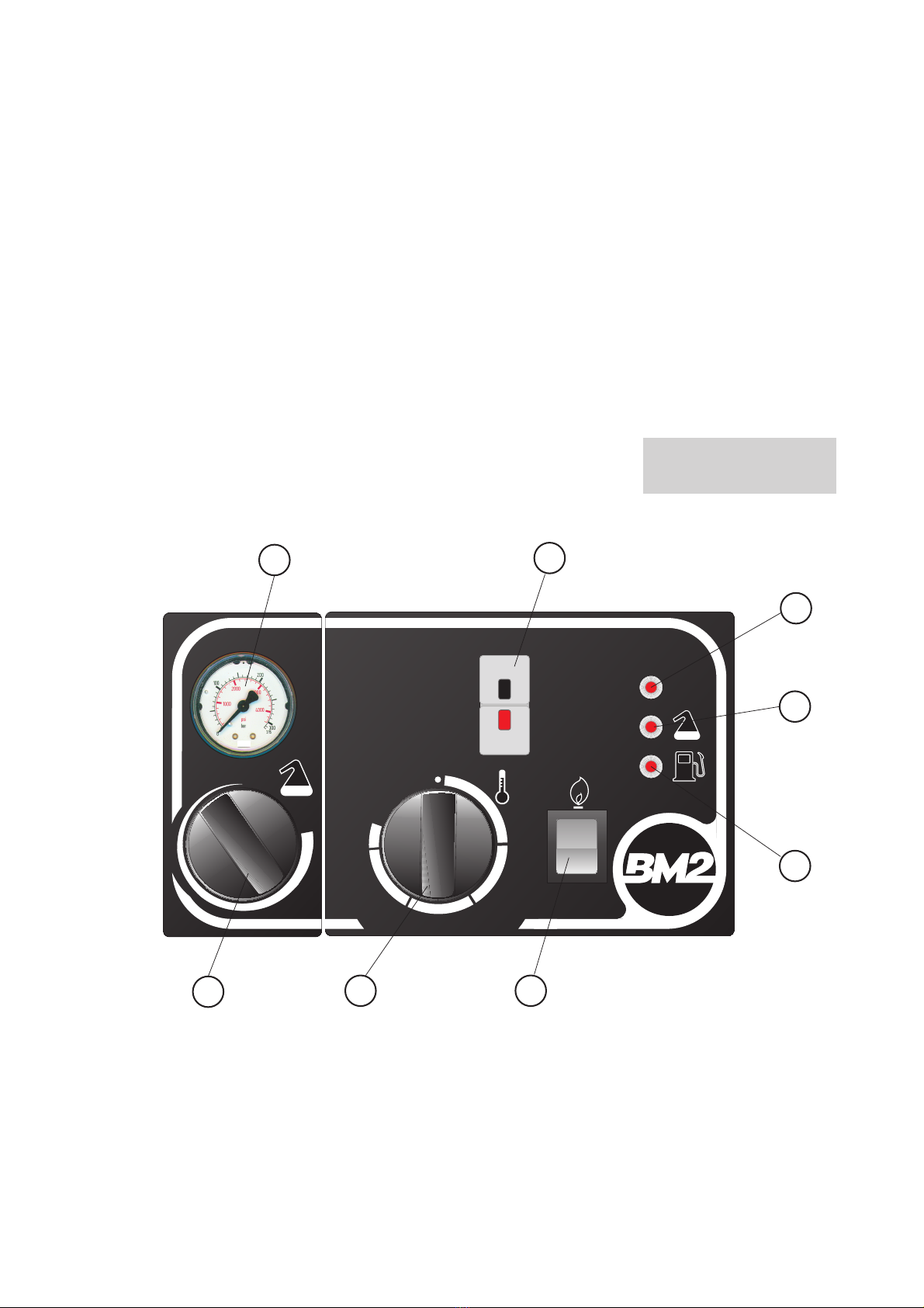
• premere l’interruttore bruciatore (3) nella posizione ;
• ruotare la manopola (4) del termostato sino a raggiungere il
valore di temperatura desiderato.
• se si desidera effettuare il lavaggio con iniezione di prodotto de-
tergente:
• Modelli IP: aprire il rubinetto dosatore detergente e regolare la
quantità di prodotto secondo le necessità del lavaggio da effettuare.
Attenzione
Si consiglia di controllare che, al termine dell’uso, il ru-
binetto dosatore detergente (5) sia stato chiuso a fondo,
poichè anche attraverso modesti trafilamenti si può ave-
re aspirazione del detergente, svuotamento del serbatoio
detergente e infine aspirazione d’aria attraverso la pom-
pa A.P.
• Modelli AR: ruotare in senso orario la testina portaugello rego-
labile (posizione ON); la quantità di detergente può essere pre-regolata
aprendo o chiudendo il dosatore detergente posto sul circuito idraulico
subito dopo la valvola di sicurezza. Al termine si deve ruotare in senso
antiorario la testina portaugello regolabile (posizione OFF).
INTERRUZIONE DEL LAVAGGIO
Se si rende necessario interrompere il lavaggio per un breve inter-
vallo di tempo é sufficiente rilasciare la leva dell’impugnatura automati-
ca; immediatamente il getto d’acqua si interrompe, il bruciatore si spe-
gne e la pompa A.P. ricircola l’acqua con un modo di funzionamento
che dipende dal modello:
• Bypass, B.P., la pompa A.P. ricircola continuamente l’acqua sino
a quando la leva dell’impugnatura automatica viene nuovamente pre-
muta;
• Fermo-macchina, F.M., dopo circa 40 - 50 secondi la pompa
A.P. si arresta completamente.
Attenzione
Per i modelli bypass il periodo di sosta non deve essere
superiore a 5 minuti, trascorsi i quali la testata della
pompa può scaldarsi sino al danneggiamento delle guar-
nizioni di tenuta delle valvole (leggere il paragrafo “In-
convenienti di funzionamento, cause e rimedi”)
L’idropulitrice B.P. o F.M. riprende automaticamente il normale
funzionamento premendo la leva dell’impugnatura automatica: il getto
d’acqua riprende e il bruciatore si riaccende.
ARRESTO DEL FUNZIONAMENTO
Per arrestare il funzionamento dell’idropulitrice, si deve:
• se il bruciatore è ancora acceso
• ruotare in senso antiorario la manopola (4) del termostato sino
a raggiungere la posizione di fondo corsa,
• lasciar funzionare a freddo la macchina per almeno 2 minuti
per raffreddare e risciacquare il circuito idraulico,
• premere l’interruttore bruciatore (3) nella posizione “0”;
• premere il tasto rosso “0” dell’interruttore magneto-termico (1).
PRECAUZIONI CONTRO IL GELO
Durante la stagione invernale l’idropulitrice non deve essere espo-
sta al gelo, se non durante il normale funzionamento; è quindi opportu-
no al termine dell’uso, dopo aver spento il bruciatore e prima di arre-
stare completamente il funzionamento, chiudere il rubinetto dell’alimen-
tazione idraulica e lasciar funzionare l’idropulitrice sino al completo
svuotamento del circuito idraulico.
Nel caso di soste prolungate a bassa temperatura si consiglia di
usare un prodotto antigelo. Dopo aver svuotato il circuito idraulico, si
mette in funzione l’idropulitrice facendo aspirare direttamente il liquido
antigelo attraverso il tubo aspirazione acqua e attraverso il tubo aspira-
zione detergente sino al completo riempimento del circuito idraulico.
SPIE DI SEGNALAZIONE (VERSIONE F.M.)
Come già descritto, le idropulitrici della versione F.M. sono equi-
paggiate con una scheda elettronica di controllo e spie per la segnala-
zione della mancanza di gasolio, acqua o detergente.
In particolare:
• Spia gasolio: quando il livello di gasolio raggiunge il valore mini-
mo (si veda il paragrafo “Inconvenienti di funzionamento, cause e rime-
di”),la spia (8) si accende e il bruciatore si arresta mentre la pompa
A.P. continua a funzionare;
• Spia acqua: quando il livello di acqua raggiunge il valore minimo
(si veda il paragrafo “Inconvenienti di funzionamento, cause e rimedi”),
la spia (6) si accende mentre pompa e bruciatore si arrestano; dopo
aver ripristinato il livello di acqua, per riavviare la macchina si deve agi-
re direttamente sull’interruttore magneto-termico (1) premendo prima il
tasto rosso “0” (arresto) e poi quello nero “I” (avviamento);
• Spia detergente: quando il livello di detergente raggiunge il valore
minimo, la spia (7) si accende mentre pompa e bruciatore si arrestano;
dopo aver ripristinato il livello di detergente, per riavviare la macchina
si deve agire direttamente sull’interruttore magneto-termico (1) pre-
mendo prima il tasto rosso “0” (arresto) e poi quello nero “I” (avvia-
mento).
DISPOSITIVO ANTICALCARE (ACCESSORIO DISPONIBILE SOLO PER I
MODELLI IP)
Il dispositivo anticalcare, da utilizzarsi solo quando l’acqua é di du-
rezza elevata, limita la formazione di depositi calcarei nella serpentina di
riscaldamento, introducendo piccole quantità di liquido anticalcare nella
vaschetta dell’acqua. E’ sufficiente riempire l’apposito contenitore con il
prodotto anticalcare prescelto: il dosatore funziona automaticamente
quando l’idropulitrice é in funzione.
DISPOSITIVO PER IDROSABBIATURA (ACCESSORIO DISPONIBILE
PER TUTTI I MODELLI)
Applicando all’idropulitrice il dispositivo per idrosabbiatura é pos-
sibile lavare e pulire superfici ricoperte da ruggine, pitture o incrosta-
zioni tenaci.
Il dispositivo per idrosabbiatura é di facile applicazione (si veda la
figura seguente): é sufficiente sostituire la lancia di lavaggio con la lan-
cia per sabbiatura (1) e inserire il tubo aspirazione sabbia (2) nel reci-
piente (3), avendo cura di utilizzare sabbia asciutta e di qualità adatta
all’uso (sabbia al quarzo o sabbia silicea).
Avviando l’idropulitrice, la sabbia (a) viene aspirata, miscelata al-
l’acqua (b) e proiettata verso la superficie da trattare, liberandola dai re-
sidui e dalle incrostazioni.
ITALIANO

5
MANUTENZIONE
Attenzione
Tutte le operazioni descritte in questo paragrafo devono
essere eseguite solo da personale professionalmente
qualificato.
Per il regolare funzionamento dell’apparecchio è necessario effet-
tuare periodicamente le seguenti operazioni, avendo cura di escludere
la linea elettrica di alimentazione dell’idropulitrice prima di iniziare.
Attenzione
Prima di iniziare l’ operazione si deve:
• Arrestare la macchina secondo le indicazioni del para-
grafo “Arresto”,
• Disinserire l'alimentazione elettrica agendo sull’inter-
ruttore di sezionamento posto sul quadro elettrico di ali-
mentazione
• Chiudere il rubinetto della linea idraulica di alimenta-
zione e svitare il raccordo portagomma del tubo ingresso
acqua.
POMPA AD ALTA PRESSIONE, POMPA A.P.
Il livello di olio nella pompa deve essere periodicamente controlla-
to utilizzando l’apposita asta di controllo livello; l’olio deve essere sosti-
tuito dopo le prime 50 ore di funzionamento e successivamente ogni
500 ore di lavoro utilizzando olio SAE 20/30 antischiuma (capacità olio:
1,2 l per i modelli IP; 0,24 per il modello 15.11 AR; 0,48 l per i modelli
15.15 AR e 20.15 AR).
FILTRO ACQUA
Il filtro, che è disposto subito dopo il raccordo di entrata acqua,
deve essere pulito frequentemente e rimontato con cura per evitare
aspirazione di aria.
BRUCIATORE E FILTRO
Periodicamente si deve pulire l’ugello gasolio e controllare le rego-
lazione e lo stato degli elettrodi: l’ugello gasolio deve essere sostituito
ogni 200 ore e gli elettrodi ogni 500 ore.
POMPA E FILTRO GASOLIO
Periodicamente la pompa gasolio deve essere smontata e ripulita
degli eventuali residui. Il filtro gasolio deve essere sostituito ogni 100
ore di funzionamento.
CAMERA DI COMBUSTIONE
Ogni 200 ore di funzionamento la camera di combustione deve es-
sere completamente smontata e pulita. Dopo aver smontato il coper-
chio superiore ed estratto il boccaglio, si sfila la serpentina e con l’au-
silio di una spazzola metallica e di un aspiratore si elimina la fuliggine e
ogni eventuale residuo della combustione.
DISINCROSTAZIONE
Periodicamente si deve effettuare il lavaggio disincrostante del cir-
cuito idraulico per eliminare i depositi calcarei che tendono a formarsi
ostruendo in particolar modo il passaggio nella serpentina di riscalda-
mento.
Per svolgere tale operazione si deve utilizzare il detergente disin-
crostante prescritto dal costruttore (rivolgersi al Servizio Assistenza
Tecnica per ulteriori chiarimenti). Il lavaggio disincrostante consiste
nel:
• chiudere il rubinetto dell’alimentazione idraulica e versare la dose
consigliata del liquido disincrostante:
• nella vaschetta dell’acqua per i modelli IP;
• in un recipiente di medie dimensioni per i modelli AR; nel me-
desimo recipiente si deve immergere anche il tubo di aspirazione del-
l’acqua dopo averlo svitato dal rubinetto di alimentazione idraulica;
• svitare il tubo A.P. dall’impugnatura automatica della lancia di la-
vaggio e, dopo aver applicato all’estremità libera un filtro in tela per
trattenere le parti calcaree, immergerlo nella vaschetta dell’acqua o nel
recipiente;
• avviare l’idropulitrice (è sufficiente il funzionamento della sola
pompa A.P.) e lasciarla funzionare per almeno 20 minuti;
• al termine della disincrostazione, si toglie il tubo A.P. dalla va-
schetta o dal recipiente e si rimuove il filtro in tela eliminando le parti
trattenute dal filtro; dopo aver ripristinato il collegamento alla rete
idraulica (modelli AR), si riapre il rubinetto dell’alimentazione idraulica
e si avvia l’idropulitrice lasciando fuoriuscire il getto d’acqua dal tubo
A.P. senza lancia di lavaggio sino a quando il circuito idraulico sia stato
completamente risciacquato.
Il lavaggio disincrostante deve essere svolto ogni 100 ore di fun-
zionamento se l’acqua è caratterizzata da valori medi di durezza totale
(25 - 30 gradi francesi ), ogni 50 - 60 ore di funzionamento se l’acqua
ha durezza totale maggiore.
TRASPORTO E MOVIMENTAZIONE
TRASPORTO DEL PRODOTTO IMBALLATO
L’imballo è stato progettato per poter essere facilmente movimen-
tato con mezzi meccanici (carrello elevatore, carro ponte, etc.): è suffi-
ciente controllare che i punti di presa siano quelli predisposti sul basa-
mento in legno.
Se necessario, più imballi possono essere sovrapposti: si deve co-
munque rispettare l’indice di sovrapponibilità riportato sull’imballo me-
desimo, avendo cura di allineare i colli ed evitare la formazione di pile
instabili.
MOVIMENTAZIONE
La movimentazione e il trasporto devono essere svolti afferrando
la macchina per la maniglia anteriore e facendola scorrere sulle ruote.
Attenzione
Non tentare mai il sollevamento manuale dell’idropulitri-
ce: il peso eccessivo potrebbe produrre danni fisici rile-
vanti.
Attenzione
Prima di spostare l’apparecchio si deve:
• Arrestare la macchina secondo le indicazioni del para-
grafo”Arresto”,
• Disinserire l’alimentazione elettrica rimuovendo la spi-
na e
• Chiudere il rubinetto dell’alimentazione idraulica e svi-
tare il tubo ingresso acqua.
ITALIANO

6
Inconveniente di funzionamento Causa Rimedio
• Verificare le caratteristiche della
alimentazione elettrica
• Verificare i collegamenti elettrici
• Fusibile bruciato (solo F.M.) • Sostituire il fusibile bruciato
• Verificare le caratteristiche della
alimentazione elettrica
• Verificare i collegamenti elettrici
• Controllare che l’ugello acqua
corrisponda a quello dichiarato di serie
• Pulire l’ugello acqua
• Regolare la valvola bypass
• Ugello della lancia intasato • Pulire l’ugello
• Ugello non adatto al tipo di macchina • Sostituire l’ugello
• Valvola bypass non tarata o sporca • Procedere alla pulizia e alla taratura
della valvola
• Anello di tenuta lato corpo pompa
usurato
• Controllare e/o sostituire l’anello di
tenuta
• Alta percentuale di umidità nell’aria • Sostituire l’olio con frequenza doppia
rispetta a quella prescritta
• Guarnizioni usurate • Sostituire le guarnizioni
• Aspirazione d’aria lungo il tubo di
entrata acqua
• Controllare che il tubo di entrata
acqua e il tappo del filtro acqua siano
ben serrati
• Rubinetto detergente aperto e
serbatoio deter
g
ente vuoto
• Riempire il serbatoio detergente e
chiudere il rubinetto deter
g
ente
• Valvola bypass bloccata • Smontare la valvola e pulirla
• Guarnizioni della pompa consumate • Sostituire le guarnizioni
• Valvole di aspirazione e/o di mandata
della pompa otturate, sporche o usurate
• Controllare le superfici di chiusura
delle valvole e pulirle
• Avviamento della macchina senza aver
scaricato completamente l’aria dal
circuito
• Togliere la lancia di lavaggio e lasciar
funzionare la pompa A.P. per alcuni
secondi
• Cuscinetti usurati • Sostituire i cuscinetti
• Motore ventilatore MV senza
alimentazione elettrica
• Controllare l’interruttore bruciatore IB
e i colle
g
amenti elettrici
• Motore e/o condensatore difettosi • Controllare il condensatore e il
motore
• Pressione di mandata dell’acqua molto
bassa
• Controllare la voce “Il getto d’acqua è
regolare, ma con valori di pressione
molto bassi”
• Pressostato non funzionante • Sostituire il
p
ressostato
• Termostato non funzionante • Sostituire il termostato
• Il getto d’acqua è regolare, ma con
valori di pressione molto bassi
• L’olio della pompa A. P. presenta
tracce di acqua
• La pompa funziona con pulsazioni
irregolari, variazioni di pressione e
rumorosità
• Il bruciatore non si avvia
(il ventilatore non funziona)
• Alimentazione elettrica interrotta o
insufficiente
• Durante il funzionamento la macchina
si ferma e il pulsante dell’interruttore
magnetotermico (1), si sgancia
• Alimentazione elettrica interrotta o
insufficiente
• Intervento del relè termico a causa di
eccessivo assorbimento di corrente
• L’idropulitrice non si avvia (premendo
l' interruttore nero dell' interruttore
magnetotermico (1), il pulsante non
rimane agganciato)
INCONVENIENTI DI FUNZIONAMENTO, CAUSE E RIMEDI
ITALIANO

7
Inconveniente di funzionamento Causa Rimedio
• Gasolio esaurito • Riem
p
ire il serbatoio
g
asolio
• Filtro
g
asolio intasato • Pulire e/o sostituire il filtro
g
asolio
• Giunto di accoppiamento
motore/
p
om
p
a
g
asolio danne
gg
iato • Sostituire il giunto
• Pom
p
a
g
asolio usurata • Sostituire la
p
om
p
a
• Ugello gasolio sporco o rovinato
• Pulire l’ugello con aria compressa o
con gasolio ed eventualmente
sostituirlo
• Scintilla d’accensione debole o
mancante
• Controllare gli elettrodi e/o il
trasformatore d’accensione
• Elettrovalvola gasolio non funzionante • Pulire e/o sostituire l’elettrovalvola
• Elettrodi d’accensione sporchi o mal
re
g
olati • Pulire e regolare gli elettrodi
• Infiltrazioni d’aria nelle tubazioni di
as
p
irazione del
g
asolio
• Controllare il serraggio di tutti i
raccordi
• Guarnizioni usurate • Sostituire le guarnizioni
• Pistone usurato • Sostituire il pistone
• Guarnizione O.R. ta
pp
o usurata • Sostituire la
g
uarnizione O.R.
• Perdite di olio tra testata e corpo
p
om
p
a
• Anelli di tenuta lato corpo pompa
usurati • Sostituire gli anelli di tenuta
• La portata di combustibile è
insufficiente
• Pulire l’ugello gasolio e/o il filtro
g
asolio
• La pressione del flusso di gasolio è
insufficiente • Tarare la pompa gasolio o sostituirla
• La serpentina di riscaldamento è
intasata da incrostazioni calcaree
• Seguire le istruzioni del paragrafo
“Disincrostazione”
• Pulire il filtro ac
q
ua
• Controllare l' impianto idraulico di
alimentazione e seguire le istruzioni del
paragrafo "Spie di segnalazione" per l'
avviamento
• L' acqua di alimentazione arriva con
pressione insufficiente
• Controllare l' impianto idraulico di
alimentazione e seguire le istruzioni del
paragrafo "Spie di segnalazione" per l'
avviamento
• La spia mancanza detergente (7) si
accende e l' idropulitrice si arresta
(solo F.M.)
• Il detergente è esaurito
• Riempire il serbatoio detergente e
seguire le istruzioni del paragrafo "Spie
di segnalazione" per l'avviamento
• La spia mancanza gasolio (8) si
accende e il bruciatore si arresta (solo
F.M.
)
• Il gasolio è esaurito • Riempire il serbatoio gasolio (il
bruciatore si avvia automaticamente)
• L' acqua di alimentazione non arriva
alla vaschetta
• La spia mancanza acqua (6) si
accende e l' idropulitrice si arresta
(solo F.M.)
• Perdite di acqua tra testata e corpo
pompa
• Pur regolando il termostato alla
massima temperatura, l’acqua è tiepida
• Il bruciatore si avvia (il ventilatore
funziona), ma non si accende la fiamma
ITALIANO
INCONVENIENTI DI FUNZIONAMENTO, CAUSE E RIMEDI

DESCRIPTION
SUPER water cleaners are suitable for the professional use where a
high temperature and high pressure washing isneeded.
Water is pushed forward by a high pressure pump, H.P. pump,th-
rough the hydraulic circuit up to the heating coil heated by a gasoil bur-
ner. It's equipped with internal detergent tank whose quantity can be
regulated, mixed with water and delivered at high pressure (models IP)
or low pressure (models AR). The operator points the water jet at the
surface to be cleaned or degreased operating the lance and pulling
theautomatic handle lever. If the automatic handle lever is realesed, wa-
ter jet will stop immediately, the burner will stop and the pump H.P. will
recycle water according to model, Bypass, B.P or Total Stop T.S. (see."
washing stoppage").
Model T.S. is equipped with an electronic device for automatic
control of the H.P. pump and burner switching on and turning off;three
warning lights will immediately show a lack of water, gasoil or deter-
gent (see."Warning lights")
Attention
The water cleaner main technical features aredetailed
on an adhesive nameplate placed on the electric switch-
board sidewall.
GENERAL ADVICE
• Follow the instructions in this manual carefully
• Do not place inflammable materials near the machine (min.di-
stance 3mt.)
• Use the water cleaner outdoors or in a well ventilated place. An
electric switchboard with suitable characteristics should be near the
machine.
• Do not use electrical extensions
• Do not point the water jet at the water cleaner or at other electri-
cal parts
• Do not use dirty or sandy water nor inflammable, chemical or
corrosive products
• Do not point the water jet at people, animals or electrical parts
• Check the machine before use and don't let animals or children
near the machine
• After use make sure the disconnecting switch is off.
INSTALLATION
PACKAGING REMOVAL
To remove packaging used for shipment:
• remove the plastic strap used to fix the machine to the wooden
base
• lift the carton box up
• remove the boards fixed on the wooden base which lock the
wheels and
• push slowly the water cleaner down the base
Attention
Never try to lift the machine manually. Doing so could re-
sult in physical injury.
ELECTRICAL CONNECTIONS
The water cleaner electrical equipment can be connected to three-
phase power mains, 50 Hz,400 V, but can be also equipped to fit three-
phase power mains, 50 Hz, 230 V (see. "Power supply voltagevaria-
tion").
Attention
The power mains must be earthed and have a magneto-
thermal switch with differential.
Power supply characteristics are detailed on the two
adhesive labels sticked on the detergent tank: before
connecting the powerlead, check that they correspond
to those of the fixed electrical plant.
POWER VOLTAGE VARIATION
All the water cleaners are fitted to be connected to three-phase
power mains, 50 Hz, 400 V. If the electric equipment should be chan-
ged to 230 V or vice-versa to fit other kind of power mains, the fol-
lowing operations must be carried out:
• replace the magneto-thermal switch and the minimum voltage
coil, setting the thermal relay to the value indicated in the technical fea-
tures scheme.
• connect the small bars of the motor terminal board as indicated
in the electrical schemes included in this manual.
• replace the adhesive label with another one showingthe selected
voltage.
LANCE PREPARATION
The pakaging contains:
• high pressure hose, H.P. already connected to the automatic
handle and to the fixed semi-lance.
• the mobile semi-lance, already prepared with the water nozzle to
be used and only for AR models, the adjustable nozzle head.
After screwing the fixed semi-lance on the mobile one, connect the
H.P. hose to the water exit connection on the water cleaner, screwing
the rapidconnection fitting.
WATER MAINS CONNECTION
Connect a rubber hose with 19 mm. internal diameter to the water
entrance pipe of the water cleaner by means of the hose coupling al-
ready screwed.
The hose from the water supply shall be fre of incrustation and im-
purities, which may compromise the proper functioning of the cleaner.
For the water cleaner to operate regularly, the feeding pressure
should beat least 1,5-2 bar: lower pressures may cause the H.P. pump
to suck air in.
GASOIL TANK
The fuel tank must be filled with clean gasoil only,avoiding acci-
dental introduction of water or any other impurity.
DETERGENT TANK
Choose the most suitable product to use. Dilute the detergent with
water according to suggested quantities. Introduce themixture into the
detergent tank.
Attention:
During filling operations, do not exceed the indicated-
maximum level to avoid pourings during machine opera-
tion.
INSTRUCTIONS FOR USE
SWITCHING ON AND WASHING
• open the water mains cock.
• switch the water cleaner on pressing the magneto-thermal switch
black key" I " (1).
Attention
The magneto-thermal switch is equipped with a minimum
voltage coil; this device prevent switching on if the
power supply voltage is lower than expected and it will
stop the machine in case of considerable voltage drop,
even if for short periods.
• pull the automatic handle lever and point the waterjet at the surfa-
ce to be cleaned.
• If you intend to use hot water:
• press the burner switch (3) to ;
• turn the thermostat knob (4) to reach the desired temperature.
• if you intend to use detergent:
• IP models: turn the detergent dispenser tap to set the suitable
quantity of product according to the type of washing.
8
ENGLISH

Attention
After use: check that the dispenser (5) tap is tightlyclo-
sed : even little leaks may cause detergent suction, de-
tergent tan kemptying and air suction through the AP
pump.
• AR models: turn clockwise the adjustable nozzle head(ON posi-
tion); the detergent quantity can be preset by opening or closing the
detergent dispenser on the hydraulic circuit after the security
valve.When finished, turn anticlockwise the adjustable nozzle head (OFF
position).
WASHING STOPPAGE
• If you want to stop washing for a while, just releasethe automatic
handle lever.The water jet will immediately stop, the burner cuts out
and the H.P. pump recycles water according to models:
• Bypass, BP, the pump recycles water continually up to the mo-
ment the automatic handle lever is pulled again;
• Automatic stop, FM, after about 40-50 seconds the H.P. pump
will completely stop.
Attention
Stoppage time must not be longer than 5 minutes in by-
pass models. After this time the pump head may heat up
and damage the valve seals (see."observed faults, cau-
ses and remedies")
The BP or TS water cleaner will automatically restart by pulling the
automatic handle lever: the water jet and the burner restart.
TURNING OFF
To turn the water cleaner off, you must:
• if the burner is still on:
• rotate anticlockwise the thermostat knob (4) up to the end,
• let the machine operate for at least 2 minutes to cool down and
rinse the hydraulic circuit,
• press the burner switch (3) to "0" position
• press the red key "0" of the magneto-thermal switch (1).
HINTS FOR FREEZING
During winter season the water cleaner must not be kept in the
cold except for normal operation; after use, turn off the burner
but,before stopping completely the machine, close the water mains
cock and let the water cleaner operate until the water in the hydraulic
circuit is expelled.
In case of long breaks at low temperatures it's advisable to use
anantifreeze product. Empty the hydraulic circuit then switch on the
water cleaner letting it suck the antifreeze through the water suction pi-
pe and through the detergent suction pipe to fill up completely the hy-
draulic circuit.
WARNING LIGHTS (F.M MODEL)
The water cleaners model T.S. are equipped with an electronical control
card and warning lights that will signal a lack of gasoil, water or detergent.
Precisely:
• Gasoil light: when gasoil level reaches its minimum value (see "obser-
ved faults, causes and remedies"), a light (8) switches on and the burner will
stop; to restart the machine, after refilling it with gasoil, directly work the
magneto-thermal switch (1) first pressing the red key "O" (turning off),then
the black one " I " (switching on).
• Water light: when water level reaches its minimum value (see "obser-
ved faults, causes and remedies"), a light (6) switches on and pump and
burner will stop while the hp pump goes on running; to restart the machine,
after refilling it with water, directly work the magneto-thermal switch (1) fir-
st pressing the red key "O" (turning off), then the black one " I " (switching
on).
• Detergent light: when the detergent level reaches its minimum value
(see "observed faults, causes and remedies"), a light (7) switches on and
pump and burner will stop; to restart the machine, after refilling it with de-
tergent, directly work the magneto-thermal switch (1) first pressing the red
key "O" (turning off),then the black one " I " (switching on).
DESCALING DEVICE (ONLY AVAILABLE FOR IP MODELS)
The descaling device must be used only in case of hardwater. It li-
mits scale formations in the heating coil introducing small quantities of
descaler into the water tub. It's enough to fill the suitable container with
the chosen descaler: the dispenser will work automatically when the
water cleaner is operating.
WATER SANDBLASTING DEVICE (OPTIONAL FOR EVERY MODEL)
Connecting the water sandblasting device to the water cleaner
could result useful to wash and clean rusty or covered with hardscales
or painting surfaces.
It's easy to connect (see picture below) : just replace the washing
lance with the sandblasting one (1) and introduce the sandsuction pipe
(2) into the container (3), using dry, quality sand suitable for this use
(quartz sand or siliceous sand).
When the water cleaner is started, the sand (a) is sucked, mixed to
water (b) and addressed towards the surface to be treated,freeing it
from scales.
MAINTENANCE
Attention
The following operations must be carried out by qualified
personnel only.
To keep the machine perfectly efficient it's necessaryto check it out
periodically. Please disconnect the electrical supply before starting any
operation.
Attention
Before starting to operate:
• Stop the machine as instructed before ("Turning off")
• Disconnect the electrical supply turning off the discon-
necting switch on the electrical switchboard
• Close the water mains cock and unscrew the hose cou-
pling of the water entrance pipe.
HIGH PRESSURE PUMP , H.P. PUMP
The oil level in the pump must be checked out periodically by
means of the proper dip stick. Oil must be replaced afterthe first 5O
working hours, afterwards every 500 working hours using ANTIFOAM
SAE 20/30 oil (oil capacity: 1,2 l for IP models; 0,24 l for 15.11 AR mo-
del; 0,48 l for 15.15 AR and 20.15AR models).
WATER FILTER
The filter, which is placed after the water entrance connection, mu-
st be frequently cleaned and carefully reinstalled to avoid airsuction.
BURNER AND FILTER
Periodically clean the gasoil nozzle and check setting and condition
of the electrodes : the gasoil nozzle must be replaced every 200 hours
and the electrodes every 500 hours.
9
ENGLISH

GASOIL FILTER AND PUMP
Periodically remove the gasoil pump and clean it.Replace the ga-
soil filter every 100 working hours.
COMBUSTION CHAMBER
Every 200 working hours, the combustion chamber must be com-
pletely removed and cleaned.
Remove the upper lid, remove the nozzle, take the coil off and eli-
minate the soot and the combustion waste products with a metallic
brush and a vacuumcleaner.
DESCALING
It's advisable to carry over a descaling washing of the hydraulic
circuit periodically to eliminate the scales which might obstruct the
passage in the heating coil.
To carry out this operation, use the descaler recommended by the
manufacturer (call the Assistance Service for information). Descaling
washing must be carried out as follows:
• close the water mains cock and pour the recommended dose of
descaler:
• into water tub for IP models;
• in a medium size container for AR models; unscrew the water
suction pipe from the water mains cock and dip it in the container too;
• unscrew the H.P. pipe from the automatic handle of the washing
lance and dip it into the water tub or into the container after placing a
cloth filter to itsfree ending to keep scales;
• start the water cleaner (H.P. pump alone may operate) and let it
operatefor about 20 minutes;
• at the end of descaling, take the H.P. pipe out of the tub or out of
the container, remove the cloth filter eliminating the scales. Reconnect
to the water mains(models AR), open the water supply cock and start
the water cleaner letting the water jet come out from the H.P. pipe
without washing lance until the hydraulic circuit has been completely
rinsed.
Descaling washing must be carried out every 100 working hours if
water is characterized by medium total hardness values (25-30French
degrees), every 50-60 working hours if water presents a higher total
hardness.
TRANSPORTING AND MOVING THE WATER CLEANER
The packaging can be easily moved mechanically (platformtruck,
overhead crane etc.). Just check that grip points are those preset on
the wooden base.
Packagings can be laid one on top of the other after reading the in-
structions and warnings placed on the packaging itself. Do not in any
case form unstable piles.
MOVING
To move the water machine use front handles and let it run on its
wheels.
Attention
Never try to lift the water cleaner manually. Doing so
could result in physical injury.
Attention
Before moving the machine:
• Turn it off as indicated before
• Disconnect electricity by pulling out the plug and
• Close the water supply cock and unscrew the water en-
trance pipe.
10
ENGLISH
OBSERVED FAULTS, POSSIBLE CAUSES AND REMEDIES
Observed fault Causes Remedies
• Check power supply characteristics
• Check electrical connections
• Burnt fuse (TS only) • Replace de fuse
• Check power supply characteristics
• Check electrical connections
• Check that the water nozzle corresponds to the
declared stock one
• Clean the water nozzle
• Adjust the bypass valve
• Clogged lance nozzle • Clean the nozzle
• Wrong nozzle • Replace the nozzle
• Bypass valve not calibrated or dirty • Clean and calibrate the valve
• Pump body side sealing ring worn out • Check and/or replace the sealing ring
• High moisture percentace in the air • Replace oil twice in comparison with prescribed
frequency
• Worn out seals • Replace seals
• Air suction in the water entrance pipe • Check that the water entrance pipe and the
water filter tap are tightly closed
• Detergent tap open and empty detergent tank • Fill the detergent tank and close the tap
• Blocked bypass valve • Remove the valve and clean it
• Pump seals worn out • Replace the seals
• Inlet/delivery valves obstructed, dirty or worn
out
• Check closure surfaces of the valves and clean
them
• The machine is started without discharging the
air completely from the circuit
• Disconnect the washing lance and let the H.P.
pump work for a few seconds
• Worn out bearings • Replace the bearings
• The water jet is regular but its pressure values
are very low
• The water cleaner won't start (pressing the
black key of the magneto-thermal switch (1) )
• Electrical supply interrupted/insufficient
• During operation the machine stops and the
magneto-thermal switch (1) switches off
• Electrical supply interrupted/insufficient
• Thermal relay intervention for excessive current
absorption
• The pump works with irregular pulsations,
pressure variations and noise
• H.P. pump oil shows water traces

11
ENGLISH
Observed fault Causes Remedies
• MV fan motor with no electrical supply • Check the burner switch IB and electrical
connections
• Faulty motor and/or capacitor • Check the capacitor and the motor
• Very low water delivery pressure • Check the point "the water jet is regular but its
pressure values are verylow"
• Manostat out of order • Replace the manostat
• Thermostat out of order • Replace the thermostat
• Consumed gasoil • Fill the gasoil tank
• Gasoil filter clogged • Clean and/or replace the gasoil filter
• Motor/gasoil pump coupling damaged • Replace the coupling
• Gasoil pump worn out • Replace the pump
• Gasoil nozzle dirty or spoiled • Clean the nozzle with compressed air or with
gasoil or replace it
• Weak/no ignition spark • Check the electrodes and/or the ignition
transformer
• Gasoil electro-valve out of order • Clean and/or Replace the electro-valve
• Gasoil flow pressure is insufficient • Clean and adjust the electrodes
• Air infiltrations in the gasoil suction pipes • Check the tightening of all nipples
• Worn out seals • Replace seals
• Worn out piston • Replace the piston
• Worn out tap O.R. seal • Replace O.R. seal
• Oil leaks between head and pump body • Pump body side sealing rings worn out • Replace the sealing rings
• Fuel delivery is insufficient • Clean the oil nozzle and/or the gasoil filter
• Gasoil flow pressure is insufficient • Calibrate the gasoil pump or replace it
• The heating coil is obstructed with scales • Follow the instructions of the paragraph
"Descaling"
• Clean the water filter
• Check the water supply plant and follow the
instructions of the paragraph"Warning lights" for
switchin
g
on
• Feeding water comes with insufficient pressure
• Check the water supply plant and follow the
instructions of the paragraph"Warning lights" for
switchin
g
on
• Lack of detergent warning light (7) lights up and
the water cleaner stops (TS only) • Consumed detergent
• Fill the detergent tank and follow the
instructions of the paragraph"Warning lights" for
switchin
g
on
• Lack of gasoil warning light (8) lights up and
and the water cleaner stops (TS only) • Consumed gasoil • Fill the gasoil tank and follow the instructions of
the paragraph"Warning lights" for switching on
• Feeding water doesn't come to the tub
• The burner won't start (the fan doesn't work)
• Lack of water warning light (6) lights up and the
water cleaner stops (TS only )
• The burner starts up (the fan is working) but the
flame doesn't light up
• Water leaks between head and pump body
• Water is warm even if thermostat is set to
maximum temperature

12
123456789
135
TR
IG 400 V
24 6
MP
MV
IT
RST
EV
PR
IB
PE
PA
3~ 400V 50Hz
MV MOTORE VENTILATORE
FAN MOTOR
IT TRASFORMATORE ALTA TENSIONE
HIGH VOLTAGE TRANSFORMER
EV ELETTROVALVOLA
ELECTRO-VALVE
PR PRESSOSTATO
MANOSTAT
TR TERMOSTATO
THERMOSTAT
IG INTERRUTTORE MAGNETO-TERMICO
MAGNETO-THERMAL SWITCH
MP MOTORE POMPA
PUMP-MOTOR
IB INTERRUTTORE BRUCIATORE
BURNER SWITCH
PA DOSATORE ANTICALCARE (A RICHIESTA SOLO PER MODELLI IP)
DESCALER DISPENSER (OPTIONAL FOR IP MODELS ONLY)
SCHEMA ELETTRICO - WIRING DIAGRAM
SUPER IP / AR
Modello by-pass
Bypass Model

13
123456789
135
TR
IG 230 V
24 6
MP
MV
IT
RST
EV
PR
IB
PE
PA
3~ 230V 50Hz
MV MOTORE VENTILATORE
FAN MOTOR
IT TRASFORMATORE ALTA TENSIONE
HIGH VOLTAGE TRANSFORMER
EV ELETTROVALVOLA
ELECTRO-VALVE
PR PRESSOSTATO
MANOSTAT
TR TERMOSTATO
THERMOSTAT
IG INTERRUTTORE MAGNETO-TERMICO
MAGNETO-THERMAL SWITCH
MP MOTORE POMPA
PUMP-MOTOR
IB INTERRUTTORE BRUCIATORE
BURNER SWITCH
PA DOSATORE ANTICALCARE (A RICHIESTA SOLO PER MODELLI IP)
DESCALER DISPENSER (OPTIONAL FOR IP MODELS ONLY)
SCHEMA ELETTRICO - WIRING DIAGRAM
SUPER IP / AR
Modello by-pass
Bypass Model
TO CHANGE THE POWER VOLTAGE SEE PAGE 8
“POWER VOLTAGE VARATION”
PER CAMBIO TENSIONE DI ALIMENTAZIONE VEDI PG. 3
“VARIAZIONE DELLA TENSIONE DI ALIMENTAZIONE”

14
MV MOTORE VENTILATORE
FAN MOTOR
EV ELETTROVALVOLA
ELECTRO-VALVE
PB PRESSOSTATO BRUCIATORE
BURNER MANOSTAT
PF PRESSOSTATO FERMO-MACCHINA
TOTAL STOP MANOSTAT
IB INTERRUTTORE BRUCIATORE
BURNER SWITCH
IG INTERRUTTORE MAGNETO-TERMICO
MAGNETO-THERMAL SWITCH
TM TELERUTTORE
TELE-CONTACTOR
MP MOTORE POMPA
PUMP MOTOR
TA TRASFORMATORE AUSILIARIO
AUXILIARY TRANSFORMER
FU FUSIBILE
FUSE
AP APPARECCHIATURA DI CONTROLLO
CHECKING EQUIPMENT
TR TERMOSTATO
THERMOSTAT
IT TRASFORMATORE ALTA TENSIONE
HIGH VOLTAGE TRANSFORMER
SA SPIA MANCANZA ACQUA
WATER LACK LIGHT
SD SPIA MANCANZA DETERGENTE
DETERGENT LACK LIGHT
SG SPIA MANCANZA GASOLIO
GASOIL LACK LIGHT
PA INDICATORE DI LIVELLO ACQUA
WATER LEVEL INDICATOR
PD INDICATORE DI LIVELLO DETERGENTE
DETERGENT LEVEL INDICATOR
PG INDICATORE DI LIVELLO GASOLIO
GASOIL LEVEL INDICATOR
N.B. DOSATORE ANTICALCARE 230 V DA
COLLEGARSI AI MORSETTI 4 - 5
N.B. DESCALER DISPENSER 230 V TO BE
CONNECTED TO BINDING CLAMPS 4 - 5
SCHEMA ELETTRICO - WIRING DIAGRAM
SUPER IP
Modello Fermo Macchina
Total Stop Model

15
PER CAMBIO TENSIONE DI ALIMENTAZIONE VEDI PG. 3
“VARIAZIONE DELLA TENSIONE DI ALIMENTAZIONE”
TO CHANGE THE POWER VOLTAGE SEE PAGE 8
“POWER VOLTAGE VARATION”
MV MOTORE VENTILATORE
FAN MOTOR
EV ELETTROVALVOLA
ELECTRO-VALVE
PB PRESSOSTATO BRUCIATORE
BURNER MANOSTAT
PF PRESSOSTATO FERMO-MACCHINA
TOTAL STOP MANOSTAT
IB INTERRUTTORE BRUCIATORE
BURNER SWITCH
IG INTERRUTTORE MAGNETO-TERMICO
MAGNETO-THERMAL SWITCH
TM TELERUTTORE
TELE-CONTACTOR
MP MOTORE POMPA
PUMP MOTOR
TA TRASFORMATORE AUSILIARIO
AUXILIARY TRANSFORMER
FU FUSIBILE
FUSE
AP APPARECCHIATURA DI CONTROLLO
CHECKING EQUIPMENT
TR TERMOSTATO
THERMOSTAT
IT TRASFORMATORE ALTA TENSIONE
HIGH VOLTAGE TRANSFORMER
SA SPIA MANCANZA ACQUA
WATER LACK LIGHT
SD SPIA MANCANZA DETERGENTE
DETERGENT LACK LIGHT
SG SPIA MANCANZA GASOLIO
GASOIL LACK LIGHT
PA INDICATORE DI LIVELLO ACQUA
WATER LEVEL INDICATOR
PD INDICATORE DI LIVELLO DETERGENTE
DETERGENT LEVEL INDICATOR
PG INDICATORE DI LIVELLO GASOLIO
GASOIL LEVEL INDICATOR
N.B. DOSATORE ANTICALCARE 230 V DA
COLLEGARSI AI MORSETTI 4 - 5
N.B. DESCALER DISPENSER 230 V TO BE
CONNECTED TO BINDING CLAMPS 4 - 5
SCHEMA ELETTRICO - WIRING DIAGRAM
SUPER IP
Modello Fermo Macchina
Total Stop Model

[bar] 150 150 200 150 150 200 150 150 200
[l/min] 11 15 15 15 21 15 15 21 15
Potenza - Power [HP] 4 5,5 7,5 5,5 7,5 7,5 5,5 7,5 7,5
Velocità - Speed [rpm] 2.800 2.800 1.450 1.450 1.450 1.450 1.450 1.450 1.450
Numero di fasi - Number of phases 333333333
Tensione - Voltage [V] 230 / 400 230 / 400 230 / 400 230 / 400 230 / 400 230 / 400 230 / 400 230 / 400 230 / 400
Frequenza - Frequency [Hz] 50 50 50 50 50 50 50 50 50
[A] 14 / 9 18 / 11 25 / 16 18,5 / 11 25 / 16 25 / 16 18,5 / 11 25 / 16 25 / 16
Bypass Bypass Bypass Bypass Bypass Bypass Fermo macchina
Total sto
p
Fermo macchina
Total sto
p
Fermo macchina
Total sto
p
Bassa pressione
Low
p
ressure
Bassa pressione
Low
p
ressure
Bassa pressione
Low
p
ressure
Alta pressione
Hi
g
h
p
ressure
Alta pressione
Hi
g
h
p
ressure
Alta pressione
Hi
g
h
p
ressure
Alta pressione
Hi
g
h
p
ressure
Alta pressione
Hi
g
h
p
ressure
Alta pressione
Hi
g
h
p
ressure
[°C] 95 95 95 95 95 95 95 95 95
[W] 4480 6160 8380 6010 8380 8380 6010 8380 8380
Delavan GPH 60° B 1,5 1,5 1,5 1,5 1,5 1,5 1,5 1,5 1,5
1/8" MEG 2504 2505 2504 2505 2507 2504 2505 2507 2504
[l] 16 16 16 16 16 16 16 16 16
[l] 16 16 16 16 16 16 16 16 16
[dBA] 78 80 78 76 78 76 76 78 76
[mm] 700 x 1000 x 940 700 x 1000 x 940 700 x 1000 x 940 700 x 1000 x 940 700 x 1000 x 940 700 x 1000 x 940 700 x 1000 x 940 700 x 1000 x 940 700 x 1000 x 940
[kg] 140 150 150 150 160 150 150 160 150
SUPER
15/11 AR
Motore - Motor
Temperatura max acqua - Max. water temperature
Alimentazione elettrica
Power supply
CARATTERISTICHE TECNICHE
TECHNICAL DIAGRAM
Taratura relé termico 230/400 V - Thermal relay calibration 230/400 V
Pressione acqua - Water pressure
Tipo circuito idraulico - Hydraulic circuit type
Erogazione detergente - Detergent delivery pressure
Portata acqua - Water output
Peso - Weight
Potenza elettrica totale - Total electrical power
Ugello gasolio - Gasoil nozzle
Ugello acqua - Water nozzle
Livello sonoro a 1 m - Noise level at 1 m
Serbatoio detergente - Detergent tank
Serbatoio gasolio - Gasoil tank
Dimensioni, L x P x A - Dimensions, L x W x H
SUPER
15/15 AR
SUPER
20/15 AR
SUPER
15/15 IP
SUPER
15/21 IP
SUPER
20/15 IP
SUPER
150 IP
SUPER
150S IP
SUPER
200 IP
This manual suits for next models
8
Table of contents
Languages:
Popular Pressure Washer manuals by other brands

Parkside
Parkside PHD 100 B2 translation of original operation manual

Craftsman
Craftsman 580.752901 Operator's manual

Briggs & Stratton
Briggs & Stratton 020545-01 Operator's manual

Aussie
Aussie RAPTOR 12 Operator's instruction manual

Nilfisk-Advance
Nilfisk-Advance SC UNO Series Instructions for use

Craftsman
Craftsman MGP-762500A owner's manual

Ryobi
Ryobi RY80935 Series Operator's manual

Hyundai
Hyundai HY210HPW-3 instruction manual

Century 400
Century 400 NINJA Warrior NWCU2250N operating instructions

Xstream
Xstream X-HW13008GENNG Operation manual

Ryobi
Ryobi RPW190BL-G operating instructions

Spitwater
Spitwater SHW88 Operating and maintenance manual