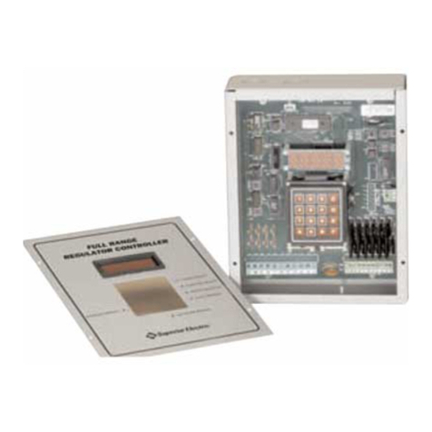
Superior Electric STABILINE WHR32 Series User manual

213709-103 Rev. E
EC99719
INSTRUCTIONS
for
STABILINE ®
Automatic Voltage Regulators
WHR32*T*** Series
Three Phase
208Y/120 X 240Y/138 Volt
Individual Phase Control
This manual also covers units with options that change the beginning of the model number to one of the following:
WHR62*T, WHR92*T, WHRS32*T, WHRS62*T, or WHRS92*T.
Superior Electric reserves the right to make engineering changes on all its products. Such refinements may affect
information given in the instructions. Therefore, USE ONLY THE INSTRUCTIONS THAT ARE PACKED WITH THE
PRODUCT.
WARNING: High voltages are present inside this unit during operation, Do not operate this unit unless all
covers are in place. Installation and servicing should only be done by qualified personnel.

2

3
TABLE OF CONTENTS
SECTION PAGE
SECTION PAGE
1.0 INSPECTION............................................... 3
1.1 UNPACKING........................................ 3
2.0 DESCRIPTION ............................................ 3
2.1 GENERAL............................................ 3
2.2 STANDARD MODEL NUMBER SYSTEM 4
2.3 THEORY OF OPERATION................... 5
3.0 INSTALLATION........................................... 5
3.1 TRANSPORTING THE REGULATOR .. 5
3.2 MECHANICAL INSTALLATION............ 5
3.3 ELECTRICAL INSTALLATION ............. 5
4.0 START UP................................................... 5
5.0 OPERATION ............................................... 6
5.1 CONTROL MODULE ASSEMBLY........ 6
5.2 SETTING OUTPUT VOLTAGE AND
SENSITIVITY POTENTIOMETERS...... 6
5.3 REMOTE SENSING............................. 6
6.0 OPTIONS.................................................... 7
6.1 NON DESIGNATED OPTIONS............ 7
6.2 MODEL No. SPECIFIED OPTIONS..... 7
6.3 ALL-BUCK AND ALL-BOOST OPERATION 9
7.0 MAINTENANCE.......................................... 10
8.0 TROUBLESHOOTING................................ 10
9.0 RATING...................................................... 12
9.1 POWER RATINGS .............................. 12
9.2 VOLTAGE RANGE CHART................. 12
9.3 GENERAL SPECIFICATIONS ............. 13
10.0 REPLACEMENT PARTS ............................ 14
10.1 ORDERING......................................... 14
10.2 CONTROL MODULE ASSEMBLY ....... 14
10.3 POWER COMPONENTS..................... 14
10.4 REPLACEMENT BRUSH ASSEMBLY. 15
10.5 AUX. POWER MODULE...................... 15
11.0 SCHEMATIC............................................... 16
12.0 FLOOR MOUNT DIMENSIONS .................. 17
1.0. INSPECTION
1.1. UNPACKING
When unpacking the unit, examine it carefully for any
shipping damage. The "Damage and Shortage"
instructions packed with the unit outlines the procedure
to follow if any parts are missing or damaged.
2.0. DESCRIPTION
2.1. GENERAL
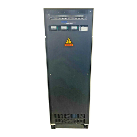
WHR32*T*** Series STABILINE®Automatic Voltage
Regulators are three phase, 208Y/120 X 240Y/138 volt,
fast acting electromechanical regulators. These WHR
Series voltage regulators regulate each line-to-neutral
voltage independently. These voltage regulators are
wye connected, have a solid state electronic control
section for each phase, and have a power section for
each phase consisting of one or more motor driven,
limited range POWERSTAT®Variable Transformers.
Units with a suffix, starting with a dash, at the end of the
model numbers are equipped with standard options.
Refer to the WHR model numbering system in the next
section for more details. See the enclosed rating charts
and unit nameplate for complete specifications.
Advantages of all WHR Series voltage regulators
include high efficiency (99% typical), high overload
capacity and low impedance. These voltage regulators
are insensitive to the load power factor or magnitude
within current rating, and have little to no effect on
system power factor. This means these regulators can
be used with any load type.

4
2.2. STANDARD MODEL NUMBER SYSTEM
The model number for each WHR Series voltage regulator identifies the various characteristics of that specific unit.
The following table explains the meaning of each character in a standard model number.
Typical Model Number WHR
S 3 2 W T F32
T -
CB
D M T 3 6 7
WHR Wide Range High Power Regulator
S Transient Voltage Suppression §
1 Single Phase (Parallel Connected)
2 Single Phase (Parallel Series connected)
3 Three Phase (wye in / wye or delta out)
6 Three Phase (delta in / delta out) §
9 Three Phase (delta in / wye or delta out) w/ zig-zag §
1 Nominal Voltage 120-127 (100)
2 Nominal Voltage 208 X 220-230-240 (277)
4 Nominal Voltage 380-400-415 X 480
6 Nominal Voltage 480 X 600
N Narrow Range
W Wide Range
S Single Control
D Double Control
T Triple Control
LNN Size Code (3 or 4 digits)
R Rack Cabinet
T Tall Cabinet
CB Input Circuit Breaker
CS Input Circuit Breaker w/ 120vac Shunt Trip
CR Input Circuit Breaker w/ 120vac Under voltage Trip Release
D Delayed Output
M Manual Bypass Switch
T Tropicalization Treatment
0 No Meter Options
1 Ammeter(s)
2 Frequency Meter w/ Alarm Contacts
3 Both 1 & 2 above
0 No Alarm Circuit Options
4 Input Voltage Range Alarm(s)
5 Phase loss/Phase reversal Alarm
6 Both 4 & 5 above
0 No Miscellaneous Options
7 Manual Raise / Lower Switch(s)
8 Soft Start
9 Both 7 & 8 above
§ Base model numbers (no options) as shown in catalog include the characters up to the hyphen (-) with the
exclusion of the TVS and Delta options.
• For lettered options not selected the letters and spaces are omitted from the model number.
• The last three numbers in the model number are all used unless all three are zero then they are omitted.

5
2.3. THEORY OF OPERATION
These units regulate AC voltage by automatically
adjusting POWERSTAT®Variable Transformers to
maintain constant output voltage.
Each of the three solid-state control units detects one
line to neutral output voltages and continually compares
it with output and accuracy settings selected by the
user. If any line to neutral voltage is out of
specifications, the control unit on that phase drives the
POWERSTAT variable transformer on that phase, by
means of a synchronous motor, to the required new
position.
3.0. INSTALLATION
3.1. TRANSPORTING THE REGULATOR
Due to its weight and size, proper lifting procedures
must be followed when transporting the unit and moving
it into the location where it is to be installed.
The proper method for moving these units is to place a
forklift under the base. A heavy frame is provided in this
area to allow lifting the unit in this manner without
damage. The 26 inch (559 mm) wide enclosures can
also be lifted by removing the top cover and using the
lifting eyes provided in the sides of the cabinet.
3.2. MECHANICAL INSTALLATION
The voltage regulator is designed for floor mounting.
When mounting the unit, allow a minimum clearance of
4 inches (100 mm) behind the unit for proper ventilation.
All internal components and wiring connections are
accessible through the front panels. A 3 foot (1000 mm)
area in front of the unit should be kept clear for
installation and service.
3.3. ELECTRICAL INSTALLATION
All WHR Series voltage regulators are designed to be
hard-wired to the input power and the load using copper
wire. When these units increase low input voltage to
give nominal output voltage, the input current is
substantially higher than the output current. Maximum
rated input and output currents for each unit are given
in the enclosed rating charts. Select a wire size that is
adequate to carry the maximum rated current as
specified by local and national code requirements.
The front panel(s) of the voltage regulator must be
removed to allow access to the input and load
terminals. To remove a panel, use a flat blade
screwdriver to release the ¼ turn fasteners, which hold
the front panel in place, and lift the panel off the base. A
full range of knockouts are provided in the base and the
rear panel of the unit for wire entry and exit.
The location of the power connections varies depending
on the options provided. On units with an input circuit
breaker, input connections are made directly to the
circuit breaker. On units without any options, the input
connections are located on the POWERSTAT variable
transformer. The input power connections are labeled
L1, L2, and L3 for the three hot lines. Load connections
are labeled T1, T2, and T3 for the hot lines and are
made to the POWERSTAT variable transformer on
units without any options.
In some cases the unit consists of more than one
enclosure. In these cases each enclosure will be
labeled “L” for input and “T” for output. In installing
multiple enclosure units refer to the second page of the
schematic supplied for point to point connections.
The input/output neutral is labeled NEUT. The input
neutral must be connected unless a zig-zag transformer
option is included.
WHR62 and WHR92 series have a zig-zag or neutral
generating transformer included. The input neutral
MUST NOT be connected to either of these series
units. The transformer in the WHR62 series is for
internal use only and no external neutral should be
connected. The zig-zag transformer in a WHR92 series
is designed to support the full rated output neutral of the
unit.
The ground terminals are a ground stud on the cabinet
wall, or a lug on the base, and must be connected to a
suitable earth ground to reduce the chance of electrical
shock.
4.0. START UP
Set the Output Voltage Range toggle switch on each
control module to either the 280Y/120 or the 240Y/138
volt position to match your application. Use the
240Y/138 volt position for 220Y/127 and 230Y/132 volt
systems. The Output Voltage Adjustment and the
Sensitivity potentiometers are set at the factory for
nominal output voltage and approximately 2% accuracy,
and should not be readjusted until the voltage regulator
is initially energized.
After all input and output connections are completed
and checked, place the front panel(s) in position and
tighten the fasteners.
Energize the regulator power source and, if provided,
place the voltage regulator's circuit breaker in the "ON"
position. The voltmeter should indicate the output
voltage, and the POWER pilot lamps and the
CONTROL pilot lamps should be lit. This indicates the
voltage regulator is operating properly.

6
5.0. OPERATION
5.1. CONTROL MODULE ASSEMBLY
5.1.1. General
The control modules contain the circuitry that senses
the output voltage and determine if correction is
needed. When correction is required this circuit sends a
raise or lower signal to the motor driven variable
transformers. To eliminate unauthorized tampering of
the control module the items marked (♦) below are
located behind the front panel.
5.1.2. Power Pilot Lamps (A1-LP1)
The POWER lamp on each control assembly lights
when power is present for the motor on that phase. This
indicates the voltage regulator is energized.
5.1.3. Control Pilot Lamps (A1-LP2)
The CONTROL lamp lights when the control assembly
sense voltage for that phase is energized. The control
sense voltage must be energized for automatic
correction of voltage changes to occur.
5.1.4. Analog Voltmeters (A1-M1)
These meters show the output voltages. There is one
meter for each phase. They sense line-to-neutral
voltage, and display line-to-neutral voltage and the
equivalent line to line voltage.
5.1.5. Output Voltage Range Toggle Switches
(A1-S1)♦
With these switches in the OFF position, the control
sense voltage for that phase is disconnected and the
control pilot lamp is not illuminated. In this position
automatic correction for voltage changes on that phase
will not take place and any change in input voltage will
be reflected in output voltage. The switches (one for
each phase) should be placed in the “208Y/120”
position to energize the control assembly sense voltage
and allow automatic correction of voltage changes.
5.1.6. Output Voltage Potentiometers ♦
These potentiometers set the line to neutral output
voltages, one for each phase. The adjustment range is
approximately ±10% of selected nominal output voltage.
5.1.7. Sensitivity Potentiometers ♦
These potentiometers adjust the voltage regulator’s
output accuracy and therefore set how much the output
voltage will change before the unit will correct. There is
a SENSITIVITY potentiometer for each sensed phase.
5.1.8. Fuses (A1-F1 to A1-F4) ♦
The four fuses located on the control module protect the
motor and sense power lines. If the POWER or
CONTROL lights are not lit, and all control settings are
proper, check for a blown fuse.
5.2. SETTING OUTPUT VOLTAGE AND
SENSITIVITY POTENTIOMETERS
Normally, the WHR Series voltage regulator should not
be operated without the front panel(s) of the cabinet in
place. However, during the initial operation of the
regulator, the front panels can be removed to allow
setting the OUTPUT VOLTAGE and SENSITIVITY
potentiometers.
5.2.1. Energize Regulator
On units equipped with a manual bypass switch ensure
it is in the REGULATOR position. Energize the
regulator power source and place the input circuit
breaker, if so equipped, in the "ON" position. The pilot
lamps should light, indicating that the voltage regulator
is energized and that the control unit is on. If necessary,
move the OUTPUT VOLTAGE RANGE switch on each
phase to the desired nominal output voltage position.
The voltmeters will indicate the output voltages.
5.2.2. Set Output
To adjust the output voltage on any phase turn the
OUTPUT VOLTAGE potentiometer, clockwise to
increase or counterclockwise to decrease, to the
desired output voltage as indicated on the voltmeter for
that phase.
5.2.3. Set Sensitivity
The sensitivity must be adjusted if the voltage regulator
hunts (any of the motor driven variable transformer
sections of the regulator continually cycles back and
forth) or if the regulator allows too great a change from
the set voltage before correction occurs.
Turning the SENSITIVITY control clockwise increases
the sensitivity to maximum (±0.75% to ±1% output
voltage accuracy). For maximum sensitivity, turn the
SENSITIVITY control on one phase clockwise to the
point where the POWERSTAT on that phase begins to
hunt. Turn the control counterclockwise (CCW) until the
hunting stops. Turn the control an additional 1/4 turn
CCW. Repeat for the other two phases.
5.2.4. Close
Replace the front cover(s).
5.3. REMOTE SENSING
Normally, these voltage regulators sense and regulate
each line to neutral voltage at the regulator's output
terminals, In some cases better control can be obtained
by regulating the voltage at another point, such as at
the end of long lines between the regulator and the
load. This is known as remote sensing.
If remote sensing is desired, move the wire connected
to terminal 6 to terminal 7 and the wire connected to
terminal 8 to terminal 9 on each control module terminal
panel. This will disconnect the control module sense
terminals from the output terminals of the regulator.
Connect remote sensing wires for each corresponding

7
line to neutral voltage (ex. 120 or 138 volts) to terminals
6 and 8 on the control modules.
Each line to neutral voltage that is sensed must be
connected to the control module that controls that
phase. If a control unit is not sensing the voltage it
controls, the POWERSTAT connected to that control
unit will drive to the end of its travel when it attempts to
correct the voltage it is not controlling. This will result in
incorrect output voltages.
6.0. OPTIONS
6.1. NON DESIGNATED OPTIONS
6.1.1. Auxiliary Power Modules (A2)
These modules are provided on units where a 120 volt
AC source is required to operate internal circuitry. The
output voltage of these modules is on terminals 1 and 2
of the terminal strip. If there is no output on these
terminals check the two fuses mounted on the same
bracket. The output of the auxiliary power modules are
used to operate fans, trip or hold on circuit breakers,
and on any other applications where 120 volts is
required.
6.1.2. Fans (B2)
On larger units fans are provided to help efficiently
remove heat generated in the cabinet. An auxiliary
power module supplies the fan operating voltage. If the
fans do not operate insure the auxiliary power module
output voltage is present.
6.2. MODEL NUMBER SPECIFIED OPTIONS
6.2.1. Circuit Breaker (CB1)
An input circuit breaker provides short circuit and
overload protection for the WHR Series Voltage
Regulators. Industrial circuit breakers with high
interrupting capacity are used. These breakers also
serve as an on/off switch for the regulator and any load
attached.
6.2.1.1. Shunt Trip (L1)
In unit where the model number designates the input
circuit breaker as “CS” the circuit breaker is equipped
with a shunt trip. A shunt trip causes the breaker to
open when voltage is applied to the shunt trip coil. The
trip coil is rated 120 volt, AC and is de-energized when
the breaker opens.
When alarm contact options and a circuit breaker trip
option are ordered together, the unit is furnished with
120 volt AC, auxiliary power module (A2) and the alarm
circuit contacts are wired to trip the input breaker. The
Shunt Trip Connections Diagram shows the typical
connections.
6.2.1.2. Under Voltage Trip (L1)
In unit where the model number designates the circuit
breaker as “CR” the circuit breaker is equipped with an
under voltage release coil. This coil allows the circuit
breaker to close when voltage is applied and opens the
breaker if the coil voltage is lost. The trip coil is rated
120 volt, AC. The coil voltage must be present in order
to close the circuit breaker.
6.2.1.3. Circuit Breaker Trip Coil & Alarm Contacts
When alarm contact options and a circuit breaker trip
option are ordered together, the unit is furnished with
120 volt AC, auxiliary power module (A2) and the alarm
contacts are wired to trip the input breaker. A
momentary switch is provided to override any alarm
activation that would trip the circuit breaker. This allows
turn on of the system and alarm options to reset. Hold
switch in while turning on the circuit breaker. Alarm
options include frequency meter, input voltage range
alarm, and phase loss / phase reversal alarm.
The following connection diagrams show typical shunt
trip and under voltage release circuits.
Shunt Trip Under Voltage Release
If you do not want the alarm contacts to trip the input
breaker, the unit can easily be re-configured.
Disable the alarms from tripping a shunt trip coil,
remove the 120 volts supplied by the auxiliary power
module to energize the coil. Removing the wires from
A2-TB1 terminals 1 and 2 that connect to the alarm
switches and TB2 does this. Do not disconnect any
other devices from this source.
Disable the alarms from tripping an under voltage trip
coil, by supplying the 120 volts directly to the coil
without going through the alarm contacts. Move the wire
on TB2-3 that comes from the auxiliary power module
to TB2-2 to accomplish this.
6.2.2. Delayed Output (A5, K2)
The delayed output option allows time for the power to
stabilize before energizing the load. This is
accomplished by adding a contactor and timer to the
regulator. When the regulator is initially energized: the
timer starts. After the preset time delay the contactor
automatically closes energizing the load. The time delay
is field adjustable from approximately 5 to 30 seconds

8
and factory adjusted to approximately 10 seconds when
shipped.
6.2.3. Manual Bypass Switch (S3)
This two-position switch, in the REGULATOR position,
provides conditioned power from input source through
the regulator to the load. In the BYPASS position the
input power and load are disconnected from the
regulator’s circuits and connects together directly. THIS
IS A NON-LOAD BREAK SWITCH AND INPUT
POWER MUST BE OFF BEFORE OPERATING. On
three phase units the neutral is not switched.
Caution: This switch is designed to provide
unconditioned power to the load if a fault condition
occurs. It does not remove all live power from the
enclosure. The manual bypass switch does not bypass
the input circuit breaker or zig-zag transformer if so
equipped.
6.2.4. Ammeters (M1)
An analog ammeter displays load current for each
phase. Each meter indicates the load current within 2%
of the meters full range.
6.2.5. Frequency meter with alarm contacts (M2)
Frequency meter displays the source frequency and
provides alarm contacts for values outside the user's
settable limits. Lower and upper limit trip relays are
factory set at 45 Hz and 65 Hz respectively. If the
frequency becomes lower or higher than user selected
values, an output relay is energized. The relay is
equipped with a form “C” normally open / normally
closed contact available for customer use.
If a circuit breaker with a trip coil is ordered with the
frequency meter, the system is configured to
automatically trip the breaker when a limit is exceeded.
6.2.5.1. Frequency Meter Instructions
The frequency meter owner’s manual is included with
the literature sent with the unit. The user can change
the meters setting without storing them in memory. If
the user changed the factory settings, and did not select
the store option, the factory setting can be reinstated by
pressing both RECALL buttons at the same time. The
stored factory settings are shown in the table below.
To return the stored settings to the factory default, tap
the ENTER key to go to the next feature then use SET
and ADVANCE keys to change the setting to those
shown below. When the display shows Store, tap the
Enter key to lock the setting into memory. If no other
setting was stored after this procedure, pressing both
RECALL keys will return the meter to these settings.
Feature Setting
Func Freq
Scale A / SC 2.00000
Offset 000000.
Range FFFF.FF
Slope A Pos
Sp lo 000045
Sp hi 000065
Gate t 01.30
Conf 1 no setting required
Conf 2 no setting required
No store Store
A front and rear view of the frequency meter is shown
below with the N.O. alarm contacts in parallel. The
alarm contacts are connected to TB4 as follows:
1 – HI relay Com 4 - LO relay COM
2 – HI relay N.O. 5 - LO relay N.O.
3 – HI relay N.C. 6 - LO relay N.C.
Frequency Meter
6.2.6. Input Range Alarm (K1)
Input voltage range alarm closes a N.O. solid state
contact when the regulator is providing maximum
voltage correction. This option senses regulator motor
drive end of travel limit switch operation.
6.2.7. Phase Loss, Phase Reversal Alarm
Contacts (A3)
Provided for three phase units only, this option senses
the three phase voltage and operates a relay (form “C ”
normally open / normally closed contact) when any
phase voltage is lost, or if the voltage sequence of the
power is reversed.
If an input circuit breaker with a shunt trip is ordered,
the system is configured to automatically trip the
breaker when there is a phase reversal. The system
might not trip the breaker when there is a phase loss
because power to operate the shunt trip may not be
available.

9
Alarm circuit contacts provided with the Frequency Trip
Meter, Input Voltage Range Alarm and Phase Loss -
Phase Reversal options are rated 5 amps 240 volts AC.
6.2.8. Manual Raise / Lower Switches (A1-S2 &
A2-S3)
Manual raise / lower switches allow the user to disable
the automatic control unit and manually raise or lower
the output voltage using the motor drive. The man/auto
switch must be in the manual position for the
raise/lower switch to operate.
6.2.9. Soft Start
The soft start option controls the WHR Series Voltage
Regulator so that when power is applied the regulator’s
output voltage starts out approximately 10% low and
after a preset time delay, the output voltage ramps up to
the selected regulated output voltage.
When input power is lost, the soft start controls
automatically drives the POWERSTAT power module(s)
to the minimum output voltage position using the output
power from a small uninterruptible power supply (UPS).
The UPS then turns off automatically. For UPS care
and maintenance see the UPS manual.
When regulator power is restored, the load voltage will
be approximately 7% less than the input voltage on
narrow range WHR Regulators and 13% less than the
input voltage on wide range models. After a short time
delay, the regulator output voltage ramps up to the
selected, regulated output voltage.
6.3. ALL-BUCK AND ALL-BOOST OPERATION
All WHR Series regulators can be connected to provide
all-buck (unit will only lower the input voltage) or
all-boost (unit will only increase the input voltage)
operation. This feature can be used to shift the nominal
voltage or to correct input voltages that are always
extremely high or extremely low.
6.3.1. 4.4.1 All-Boost Operation
When connected for all-boost, the units will bring extra
low voltages up to nominal, but will not correct high
input voltages. Since operation in the all-boost mode
will increase the voltage and heating in the WHR
regulator, the rated load current, and in some cases the
maximum rated nominal input voltage, must be
reduced. Refer to the “All Buck and All Boost Rating
Chart” for the all-boost ratings. For all-boost operation
the input line to each POWERSTAT variable
transformer must be moved from terminal 2 to terminal
5.
6.3.2. 4.4.2 All-Buck Operation
When connected for all-buck operation, the units will
bring extra high input voltages down to nominal, but will
not correct low input voltages. Since all-buck operation
reduces the voltage in the regulator, the nominal input
voltage can be increased. The current ratings remain
the same. Refer to the “All Buck and All Boost Rating
Chart” for all-buck ratings. All-buck operation requires
moving the input line to each POWERSTAT Variable
Transformer from terminal 2 to terminal 4.
All Buck and All Boost Rating Chart
Standard Rating All Buck Operation All Boost Operation
(max output voltage = input voltage) (min output voltage = input voltage)
Maximum Nominal
Input Voltage
§
Minimum
Output
Voltage
(% of
Input)
† High
Input
Voltage
Range
(% of
Output)
Maximum Nominal
Input Voltage
§
Maximu
m Output
Voltage
(% of
Input)
‡ Low
Input
Voltage
Range
(% of
Output)
Current
De-rating
(% of
rated)
Voltage Range 50 Hz 60 Hz 50 Hz 60 Hz
208 X 240 Narrow 240 270 80% 125% 173 208 125% 75% 77%
Wide 260 300 67% 150% 173 208 150% 65% 72%
§ Selectable output voltage is a function of the control module and must remain within the limits specified in the unit rating charts.
† In all buck operation the input voltage range is from the selected output voltage to the 'high input voltage range'.
‡ In all boost operation the input voltage range is from the 'low input voltage range' to the selected output voltage.

10
7.0. MAINTENANCE
To ensure maximum life of the equipment, the following
should be part of an annual maintenance program.
Warning
De-energize unit before performing maintenance.
Voltages are present inside this unit which can
cause injury. Therefore, only personnel qualified to
service electrical equipment should perform
maintenance on this unit.
7.1. Vacuum the voltage regulator inside and out to
remove accumulated dirt, which could lead to
overheating or insulation failure.
7.2. Tighten all electrical connections, particularly all
power wiring to, and in, the unit.
7.3. Inspect all variable transformer brushes and
commutators for signs of wear or pitting. Replace as
required. See diagram below.
Do not attempt to clean a commutator with an
abrasive such as sandpaper or a file. This will ruin
the soft precious metal plating on the commutator and
will shorten the life of the unit. It is normal for
commutators to become black due to carbon brush
tracking. If a commutator is to be cleaned, use
denatured alcohol and a soft cloth.
7.4. Inspect the variable transformer drive belts,
sprockets, gears, cams, etc. for signs of slippage or
wear and adjust as required.
7.5. Check the variable transformer radiator(s) (the
die cast part that holds the brush assembly) for signs of
slippage, and see if all brushes driven by the same
motor are aligned with each other. The alignment of the
radiator and brushes depends on the setscrews that
hold the variable transformer center tube(s) to the shaft
and the setscrews that hold the radiator to the center
tube. Adjust and tighten as needed.
7.6. Lubrication of the WHR Series voltage regulator
is not required since it has been lubricated at the factory
for its lifetime.
8.0. TROUBLESHOOTING
WHR Series voltage regulators will provide long,
reliable service with little attention. Unless the unit is
overloaded, there is little likelihood of component
failure.
Warning
Voltages are present inside this unit which can
cause injury. Therefore, only personnel qualified to
service electrical equipment should perform
trouble-shooting procedures on this unit.
If the regulator fails to operate correctly, the following
checks will help locate and correct the problem. Refer
to the schematic, rating chart and replacement parts list
for further information.
8.1. Check the load connected to the voltage
regulator to be sure the unit's output current rating is not
being exceeded.
8.2. See if the POWER pilot lamps are on. If a lamp is
not on, there is no power to the voltage regulator, or
control module fuses F1 and F2 (POWER fuses) are
blown, or the lamp has burned out. Check the POWER
fuses (F1 and F2). Check the power input to the unit to
be sure the voltage is within the range specified for the
selected output voltage.
8.3. Check the output voltmeters. If a meter shows
zero output voltage, check the input line, control module
fuses F3 and F4 (CONTROL fuses), remote sense
wiring if applicable, and input connections. If so
equipped, check position of input circuit breaker and
manual bypass switch.
8.4. Check the CONTROL pilot lamps. If one is not lit,
check it's VOLTAGE RANGE switch to be sure it is on
and check for blown CONTROL fuses (F3 and F4). If
applicable, check the remote sense wiring.
8.5. If the motor hunts (cycles continuously), readjust
the SENSITIVITY control.
8.6. If a motor drives a POWERSTAT variable
transformer to one end of its travel, and the voltage
decreases when it should increase or increases when it
should decrease, check to see if the input and output
power connections to the voltage regulator are
reversed. If applicable, check the remote sense wiring.
8.7. If the unit has been reworked or repaired, check
to see if the leads driving the motor have been
reversed. A1-TB1-2 and A1-TB1-3 provide the motor
power to lower and raise the motor with A1-TB1-1 being
the common for both AC voltages.

11
8.8. If the motor continues to hum or buzz after the
OUTPUT VOLTAGE RANGE switch is turned off, the
solid-state switch controlling the motor may be
defective. De-energize the input line to the voltage
regulator, and replace the control board.
8.9. If the motor has driven to one end or does not
drive at all, check to ensure the motor drive is
functioning correctly. Refer to the unit's schematic
diagram to complete the following steps:
De-energize the input line to the voltage regulator;
place the OUTPUT VOLTAGE RANGE switch in the
center (off) position, and remove POWER fuses F1 and
F2 on each control module.
Apply 115 volts AC between terminals A1-TB1-1 and
A1-TB1-2 on the control module, or to the
corresponding terminals at the motor board terminal
strip (TB1). These nine junction terminal strips are
connected point-for-point. The motor should turn the
variable transformer counter clockwise (viewed from
top) so as to lower the output voltage until it reaches the
end of its travel, where the limit switch will prevent
further rotation in that direction.
Apply 115 volts between terminals A1-TB1-1 and
A1-TB1-3 should run the motor in the opposite direction
until a limit switch stops the motor at the end of travel.
If the motor operates successfully in this test the
problem may be with the control board.
8.10. Inspect the POWERSTAT Variable Transformer
brush(s) and commutator(s) for signs of wear or
damage. The brush assemblies on the variable
transformer section will not need replacement under
normal conditions. When excessive brush wear or
commutator damage occurs, it is usually the result of an
overload. If either condition exists, the POWERSTAT
Variable Transformer section or the brush must be
replaced or repaired. Check the load to be sure the
output current rating of the voltage regulator is not
being exceeded.
Do not attempt to clean a commutator with an
abrasive such as sandpaper or a file. This will ruin
the soft precious metal plating on the commutator
surface and will shorten the life of the unit. It is normal
for commutators to become black due to carbon brush
tracking. If a commutator is to be cleaned, use
denatured alcohol and a soft cloth.
8.11. Check the variable transformer radiator(s) (the
die cast part that holds the brush assembly) for signs of
slippage, and see if all brushes driven by the same
motor are aligned with each other. The alignment of the
radiator and brushes depends on the setscrews that
hold the variable transformer center tube(s) to the shaft
and the setscrews that hold the radiator to the center
tube. Adjust and tighten as needed.

12
9.0. RATING
9.1. POWER RATINGS
The WHR32*T*** Series ratings are shown below:
INPUT:
VOLTAGE: 208Y/120 X 240Y/138
FREQUENCY: 50/60 Hz X 60 Hz
CONNECTION: 3 Phase, 4 Wire, Wye
RANGE: -30% to +15% of Selected Output
OUTPUT:
VOLTAGE: 208Y/120 X 240Y/138
CONNECTION: 3 Phase, 3 or 4 Wire
Model Number
(base unit)
Rated Load Max.
Input
Amps
Amps kVA at
208 V 240 V
WHR32WTE31 42 15 - 60
WHR32WTF31 72 25 30 100
WHR32WTF32 144 50 60 200
WHR32WTF33 216 75 90 300
WHR32WTF34 288 100 120 400
WHR32WTF35 360 125 150 500
WHR32WTF36 432 150 175 600
WHR32WTF37 504 175 200 700
WHR32WTF38 576 200 225 800
WHR32WTF39 648 225 250 900
WHR32WTF65 720 250 300 1000
WHR32WTF66 850 300 350 1200
WHR32WTF67 1000 350 400 1400
WHR32WTF68 1150 400 450 1600
WHR32WTF96 1300 450 525 1800
WHR32WTF97 1500 525 600 2100
WHR32WTF98 1700 600 675 2400
WHR32WTF99 1900 675 750 2700
INPUT:
VOLTAGE: 208Y/120 X 240Y/138
FREQUENCY: 50/60 Hz X 60 Hz
CONNECTION: 3 Phase, 4 Wire, Wye
RANGE: -20% to +10% of Selected Output
OUTPUT:
VOLTAGE: 208Y/120 X 240Y/138
CONNECTION: 3 Phase, 3 or 4 Wire
Model Number
(base unit)
Rated Load Max.
Input
Amps
Amps kVA at
208 V 240 V
WHR32NTD31 30 10 13 37
WHR32NTE31 50 18 20 60
WHR32NTF31 80 28 33 100
WHR32NTF32 160 55 65 200
WHR32NTF33 240 85 100 300
WHR32NTF34 320 110 125 400
WHR32NTF35 400 140 150 500
WHR32NTF36 480 170 200 600
WHR32NTF37 560 200 225 700
WHR32NTF38 640 225 250 800
WHR32NTF39 720 250 300 900
WHR32NTF65 800 285 325 1000
WHR32NTF66 960 350 400 1200
WHR32NTF67 1120 400 450 1400
WHR32NTF68 1280 450 525 1600
WHR32NTF96 1450 525 600 1800
WHR32NTF97 1680 600 675 2100
WHR32NTF98 1900 675 750 2400
WHR32NTF99 2150 750 850 2700
9.2. VOLTAGE RANGE CHART
At the very extremes of the input range the output
voltage may become slightly higher or lower than would
otherwise be the case. This voltage range chart shows
the output voltages produced over the input range.

13
9.3. GENERAL SPECIFICATIONS
Electrical:
Output Accuracy Adjustable from 1% to 3%
Response Time 0.025 seconds at 60 Hz,0.030 seconds at 50 Hz
Load Capacity 100% rated continuous
200% rated 60 seconds
400% rated 3 seconds
600% rated 1 second
800% rated 0.5 second
1000% to 2500% 1/2 cycle inrush
Load Power Factor 0 lagging to 0 leading
Load Crest Factor 6 Max (I peak / I RMS)
Efficiency 99% typical, at full load
Heat Generated BTU (typical) = 35 x rated Kva
Harmonic Distortion Less than 1% added
Surge Withstand Capability 6000 volts per IEEE C62.41, location category B
Impedance 1% (typical) without transient suppression option
2% (typical) with transient suppression option
Transverse-Mode Noise
Attenuation
40 dB (typical) with transient suppression option
Environmental:
Service Conditions Units are housed in NEMA 1 ventilated enclosures, intended for indoor use
under usual service conditions.
Temperature
Operating Average ambient temperature for any 24 hour period not to exceed 30°C
(86°F), and maximum temperature not to exceed 40°C (104°F). Average
ambient temperature for any 24 hour period may be increased to 40°C
(104°F),and the maximum temperature may be increased to 50°C (122°F),if
the load is decreased to 90% of standard rating. Minimum temperature is
0°C (32°F).
Storage -40°C to +70°C (-40°F to +158°F)
Humidity (Operating and Storage)
Units without tropicalization 10 to 75% average relative humidity for any 7 day period, and maximum
relative humidity not to exceed 95% non-condensing.
Units with tropicalization 10 to 95% average relative humidity and maximum relative humidity not to
exceed 95% non-condensing.
Altitude
Operating Maximum Altitude Derating
6,600 Ft.(2,000 meters) No de-rating
10,000 Ft.(3,000 meters) load to 95%,ambient 30°C (86°F)
15,000 Ft.(4,500 meters) load to 90%,ambient 20°C (68°F)
Storage 50,000 Ft.(15,000 meters)max

14
10.0.
REPLACEMENT PARTS
10.1. ORDERING
Because this manual covers a full series of units it is
impractical to provide a full list of replacement parts. To
order a part not listed in this manual, provide the unit
model number, serial number, and date code.
Reference the part by schematic reference symbol,
description and part number if available.
10.2. CONTROL MODULE ASSEMBLY
The same control modules are used throughout this
standard WHR Series STABILINE
®
Automatic Voltage
Regulators and are shown below. Tropicalized units
have a similar control module but some of the parts are
specially treated and therefore have a different part
number.
FLOOR MOUNT CONTROL MODULE ASSEMBLY (A1)
Standard
Tropicalized
Reference Symbol
Part Description
Part Number
Part Number
A1 CONTROL MODULE 213243-003 213243-006
A1-A1 CONTROL BOARD 227412-001 227412-001-SM
A1-F1,F2,F3,F4 FUSE, 600V 104364-003
A1-LP1,LP2 LIGHT, INDICATOR, GREEN 227571-001
A1-M1 VOLTMETER 212917-004
A1-S1 SWITCH, ROCKER SPST ON/-/ON 227572-002
10.3. POWER COMPONENTS
The following parts differ depending on the model. Part number can be determined by the letter designations for
range and size code in the base model number. Ex. WHR32WTF33
Standard Unit
Part Number for Range & Size Code letters listed
Reference
Symbol Part Description
WTF WTE NTF NTE NTD
T1 POWERSTAT, VARIABLE
TRANSFORMER 212995-001 216973-001 216513-003 216973-002 216969-002
REPLACEMENT BRUSH ASSEMBLY 017702-011 017702-003 017702-011 017702-003 176012-001
T2 CHOKE, PARALLELING 006724-000 006724-000
Tropicalized Units only …
Part Number for Range & Size Code letters listed
Reference
Symbol Part Description
WTF WTE NTF NTE NTD
T1 POWERSTAT, VARIABLE
TRANSFORMER 218312-014 218312-008 218312-013 218312-009 218312-003
REPLACEMENT BRUSH ASSEMBLY 017702-013 017702-007 017702-013 017702-007 176003-003
T2 CHOKE, PARALLELING 006724-000 006724-000

15
10.4. REPLACEMENT BRUSH ASSEMBLY
Each POWERSTAT®Variable Transformer contains a durable brush assembly. These assemblies are designed to
reduce the need for attention or replacement, however, because these are moving parts that rely on contact friction
to operate properly, an annual inspection is suggested. Refer to the maintenance section of this manual for details.
The replacement brush assembly is listed along with its corresponding POWERSTAT Variable Transformer in the
power component section.
10.5. AUX POWER MODULE
There are two standard power modules used throughout this WHR Series of STABILINE®Automatic Voltage
Regulators. One is used for Line to Line connections and the other for Line to Neutral connection.
Line
-
Line
Line
-
Neut.
Reference Symbol
Part Description
Part Number
Part Number
A2 CONTROL POWER MODULE 217487-002 217487-001
A2-F1,F2 FUSE 104364-003 104364-003
A2-T1 TRANSFORMER, POWER 227602-001

16
11.0. SCHEMATIC (For reference only, use full size supplied with unit)

17
12.0. FLOOR MOUNT DIMENSIONS
Enclosures A through G
Note: All dimensions are inches [millimeters]

18
Enclosures A through G continues
Note: All dimensions are inches [millimeters]

19
Enclosures A through G continues
Note: All dimensions are inches [millimeters]

20
Enclosures DPLUS through GPLUS
Note: All dimensions are inches [millimeters]
Table of contents
Other Superior Electric Controllers manuals

Superior Electric
Superior Electric 9T92PVC2 Series User manual

Superior Electric
Superior Electric POWERSTAT FRM2000 Series User manual

Superior Electric
Superior Electric STABILINE WHR5206 User manual

Superior Electric
Superior Electric STABILINE WHR34 T Series User manual

Superior Electric
Superior Electric STABILINE WHR22 Series User manual

Superior Electric
Superior Electric WHR32 S Series User manual

Superior Electric
Superior Electric STABILINE WHR34 S Series User manual