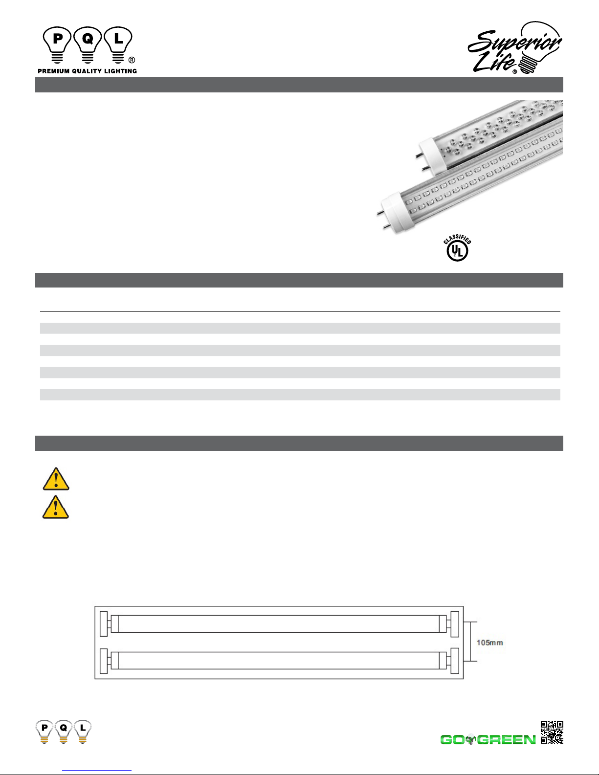
Superior Life T10 User manual

LED LINEAR T10
INSTALLATION INSTRUCTIONS
ORDERING
NOTE: Due to multiple input voltage integrated circuits, some items are not compatible with dimming devices.
These items may not be compatible with all electronic transformers
LM79
CERTIFIED
LM80
CERTIFIED
Key: SL = Superior Life®
WARNINGS
General Information
• Models were only evaluated for installation intended to replace a uorescent lamp
where it is necessary to modify the luminaire.
• These LED Tube Lamps are intended to retrot maximum four lamps, surface
mount, or Type IC recessed mount uorescent luminaires that use straight tubular
lamps.
• These lamps should be installed by a licensed electrician.
• These lamps work on line voltage and require all ballasts to be removed before the
lamp is to be installed in the luminaire.
• These lamps are to be used in indoor dry or damp location only. Not suitable for wet
location luminaire.
• Some lamps are not to be used with a light dimmer. The starters need to be
bypassed. (Items labeled dimmable can be used with dimming devices).
Always contact ground lead to luminaire where applicable.
WARNING: To reduce the risk of fire or electrical shock,do not expose this
apparatus to rain or moisture luminaire conversion, retrofit.
WARNING DO NOT OPEN: To reduce the risk of electrical shock, do not remove
cover and caps No user-serviceable parts inside. Refer servicing to qualified service personnel.
FOR USE ONLY WITH FLUORESCENT LUMINAIRES IDENTIFIED IN MANUFACTURER’ S INSTRUCTIONS
THIS PRODUCT MUST BE INSTALLED IN ACCORDANCE WITH THE APPLICABLE INSTALLATION CODE BY
A PERSON FAMILIAR WITH THE CONSTRUCTION AND OPERATION OF THE PRODUCT AND THE HAZARDS
INVOLVED.
These lamps can be used in any standard T8 or T10 lamp luminaire, allowing for it’s minimum spacing requirements
Maximum distance between lamps pin sockets
ITEM# DESCRIPTION BULB WATT CHIP COLOR LUMENS CRI VOLT BASE HOURS CASE
90679 LED 220 3’ 14WT10/4100K/NATURAL BRITE/CLEAR - SL® T10 14 SMD 4100K 1400 75 110-277V MED BI PIN 50,000 25
90692 LED 290 4’ 18WT10/CL/30K/120V/DIMMABLE - SL® T10 18 SMD 3000K 1650 75 120V MED BI PIN 50,000 25
90688 LED 290 4’ 18WT10/CL/40K/120V/DIMMABLE - SL® T10 18 SMD 4000K 1650 75 120V MED BI PIN 50,000 25
90632 LED 290 4’ 18WT10/5500K/CLEAR/VITA-BRITE® T10 18 SMD 5500K 1960 75 110-277V MED BI PIN 50,000 25
90639 LED 290 4’ 18WT10/5500K/CLEAR/VITA-BRITE® - DIMMABLE T10 18 SMD 5500K 1960 75 110-277V MED BI PIN 50,000 25
90640 LED 350 5’ 22WT10/4100K/NATURAL BRITE/CLEAR T10 22 SMD 4100K 2300 72 110-277V MED BI PIN 50,000 25
90648 LED 350 5’ 22WT10/5500K/CLEAR/VITA-BRITE® T10 22 SMD 5500K 2300 72 110-277V MED BI PIN 50,000 25
90643 LED 580 8’ 36WT10/4100K/NATURAL BRITE/CLEAR T10 36 SMD 4100K 3920 70 110-277V SINGLE PIN 50,000 25
PREMIUM QUALITY LIGHTING • www.PQLighting.com
0615
© 2015 PQL, Inc. • 2285 Ward Avenue • Simi Valley, Ca 93065 • 800.323.8107 • Fax: 877.619.7053

LED LINEAR T10
INSTALLATION INSTRUCTIONS
WARNING: Risk of re or electric shock. Retrot kit installation
requires knowledge of uorescent lighting luminaires electrical
systems. If not qualied, do not attempt installation. Contact a
qualied electrician.
WARNING: Risk of re or electric shock. The electrical rating of
this product is AC100V-277V, the installer must determine whether
they have AC100V-277V at the luminaire before installation.
WARNING: Risk of re or electric shock. Install this kit only in the
luminaires that have the construction features and dimensions
shown in the drawings.
WARNING: Risk of re or electric shock. Luminaires wiring,
ballasts, or other electrical parts may be damaged when drilling for
installation of retrot kit hardware. Check for enclosed wiring and
components.
WARNING: To prevent wiring damage or abrasion, do not expose
wiring to edges of sheet metal or other sharp objects.
WARNING: THE RETROFIT ASSEMBLY IS ACCEPTED AS A
COMPONENT OF A FLUORESCENT LUMINAIRE WHERE THE
SUITABILITY OF THE COMBINATION SHALL BE DETERMINED
BY CSA OR AUTHORITIES HAVING JURISDICTION.
WARNING: Risk of re or shock. Do not use this retrot kit in
luminaires employing shunted bi-pin lampholders.
Note: Shunted lamp holders are found only in uorescent
luminaires with Instant-Start ballasts. Instant-start ballasts can
be identied by the words “Instant Start” or “I.S.” marked on
the ballast. This designation may be in the form of a statement
pertaining to the ballast itself, or may be combined with the
marking for the lamps with which the ballast is intended to be
used, for example F40T12/IS.
IMPORTANT SAFETY INSTRUCTIONS
• Do not make or alter any open holes in an enclosure of wiring or
electrical components during kit installation.
• Not for use with dimmers; unless labeled dimmable.
• The end retrot luminaire has been modied and can no longer
operate the originally intended lamp.
• Caution-Risk of Electric Shock-Use in Dry and Damp Locations
Only.
• Risk of Electric shock-Do Not Use Where Directly Exposed To
Water.
• This device is not intended for use with emergency exit xtures
or emergency exit lights.
DANGER–RISK OF SHOCK–DISCONNECT POWER BEFORE INSTALLATION
INSTALL INSTRUCTIONS
1 Switch off power supply BEFORE COMMENCING WORK
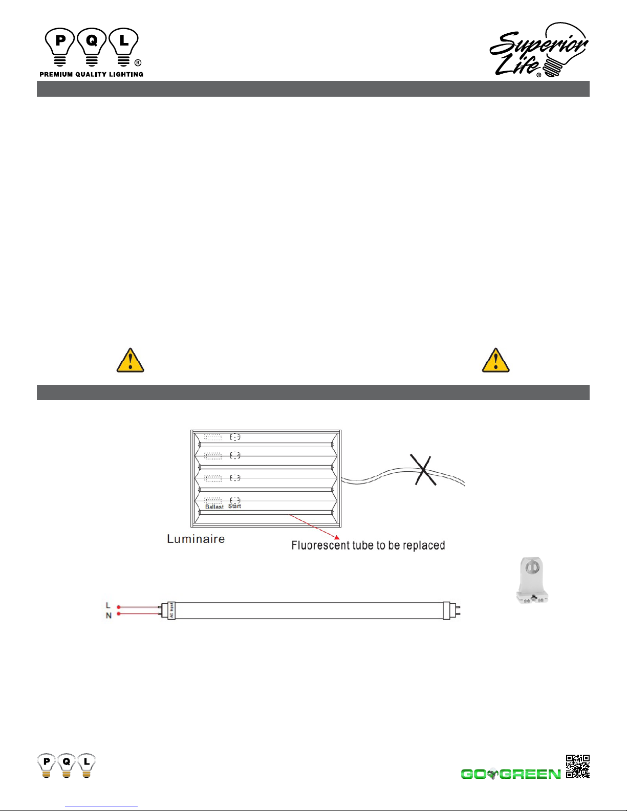
2 Luminaire Retrofit Steps
Note: 4’ 18WT10 Must be
installed using un-shunted
sockets Part# 210-13661-SNP
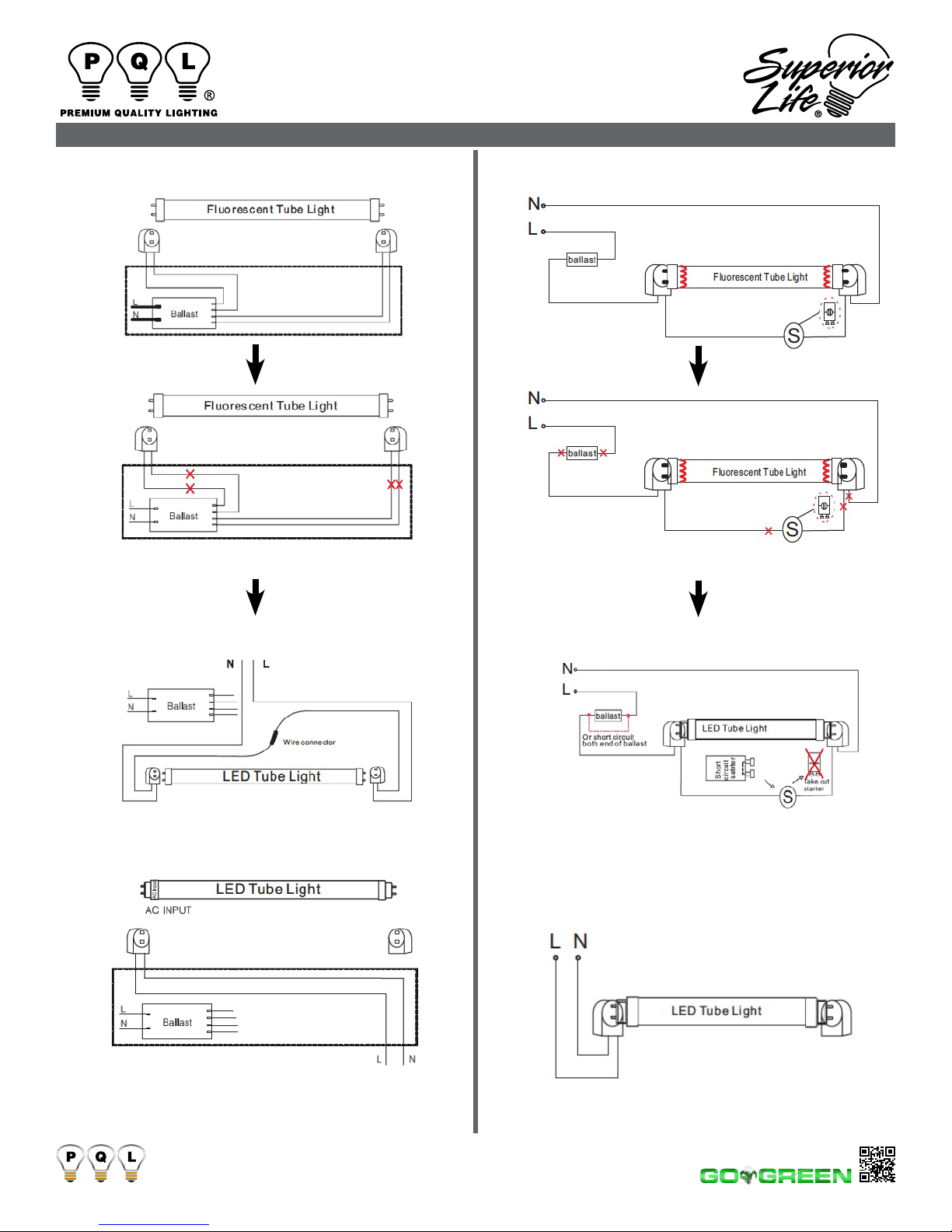
1) Principle of wire circuit
Input Voltage: AC100-277V 50/60Hz
2) Retrot Steps
Switch off power supply BEFORE COMMENCING WORK
1)Choose wires connect method from A, B, C, D options according to the ballast and lumunaire type.
2) Use the electric rubberized fabric or pressing wire cap to encase all the power supply cord parts
which were cut off, especially the end sides of power supply cord.
3) Afx included warning labels to xtures near lamp connection/sockets of xture so they are visible
to bulb installers.
4) Install LED tube Lighting.
5) Switch on power.
PREMIUM QUALITY LIGHTING • www.PQLighting.com
0615
© 2015 PQL, Inc. • 2285 Ward Avenue • Simi Valley, Ca 93065 • 800.323.8107 • Fax: 877.619.7053
WARNINGS

LED LINEAR T10
INSTALLATION INSTRUCTIONS
INSTALL INSTRUCTIONS
A. Retrofit Luminaire with Electronic Ballast
Two methods for wiring: Wiring Method 1 and Wiring Method 2.
1
2
Remove diffuser (if applicable) and uorescent lamp.
Cut all wires which connected to ballast.
3A Wiring Method 1 Installing the LED tube into the
xture with both sockets live.
3B Wiring Method 2 Connecting the side with “AC Input”
label into the holder with “L”& “N” wires. The tube will
not be damaged if installed in reverse.
Connect two wires to branch circuit L and N according
to the gure above.
OR
B. Retrofit Luminaire with Magnetic Ballast
Two methods for wiring: Wiring Method 1 and Wiring Method 2.
1
2
3A Wiring Method 1 Installing the LED tube into the
xture with both sockets live.
3B Wiring Method 2 Connecting the side with “AC Input”
label into the holder with “L”& “N” wires. The tube will
not be damaged if installed in reverse.
Connect two wires to branch circuit L and N according
to the gure above.
Remove diffuser (if applicable) and uorescent lamp.
Cut all wires which connected to ballast.
Note:
1. Must remove starter
2. Install short circuit starter
OR
PREMIUM QUALITY LIGHTING • www.PQLighting.com
0615
© 2015 PQL, Inc. • 2285 Ward Avenue • Simi Valley, Ca 93065 • 800.323.8107 • Fax: 877.619.7053

LED LINEAR T10
INSTALLATION INSTRUCTIONS
INSTALL INSTRUCTIONS
C. Retrofit with Two Lamps/One Ballast
Two methods for wiring: Wiring Method 1 and Wiring Method 2.
1
2
Remove diffuser (if applicable) and uorescent lamp.
Cut all wires which connected to ballast.
3A Wiring Method 1 Installing the LED tube into the
xture with both sockets live.
3B Wiring Method 2 Connecting the side with “AC Input”
label into the holder with “L”& “N” wires. The tube will
not be damaged if installed in reverse.
Connect two wires to branch circuit L and N according
to the gure above.
OR
D. Retrofit with 4 Lamps/One Ballast
Two methods for wiring: Wiring Method 1 and Wiring Method 2.
1
2
3A Wiring Method 1 Installing the LED tube into the
xture with both sockets live.
3B Wiring Method 2 Connecting the side with “AC Input”
label into the holder with “L”& “N” wires. The tube will
not be damaged if installed in reverse.
Remove diffuser (if applicable) and uorescent lamp.
Cut all wires which connected to ballast.
OR
Connect two wires to branch circuit L and N according
to the gure above.
PREMIUM QUALITY LIGHTING • www.PQLighting.com
0615
© 2015 PQL, Inc. • 2285 Ward Avenue • Simi Valley, Ca 93065 • 800.323.8107 • Fax: 877.619.7053

LED LINEAR T10
INSTALLATION INSTRUCTIONS
INSTALL INSTRUCTIONS
3. Install LED tube and Earth (Ground)
Ballast and Starter must be removed per instructions in step“ 2 Luminaire Retrot Steps”
4. Connect to power
5. Pin Rotated 0-90 degree
This luminaire has been modified and no longer operates Fluorescent Lamps.
**Afx included warning
labels to xtures near lamp
connection/sockets of xture
so they are visible to bulb
installers.
0615
© 2015 PQL, Inc. • 2285 Ward Avenue • Simi Valley, Ca 93065 • 800.323.8107 • Fax: 877.619.7053
PREMIUM QUALITY LIGHTING • www.PQLighting.com
Table of contents
Popular Lighting Equipment manuals by other brands

Viking
Viking BLK-1A Technical practice

ProLights
ProLights UNICO user manual

InoTec
InoTec CLS FUSION 7Ah Mounting and operating instructions

Commercial Electric
Commercial Electric MAGIC-L21-12 Use and care guide

Lightolier
Lightolier DX Series Specification sheet

Flowtoys
Flowtoys Full Vision Flower Stick quick start guide