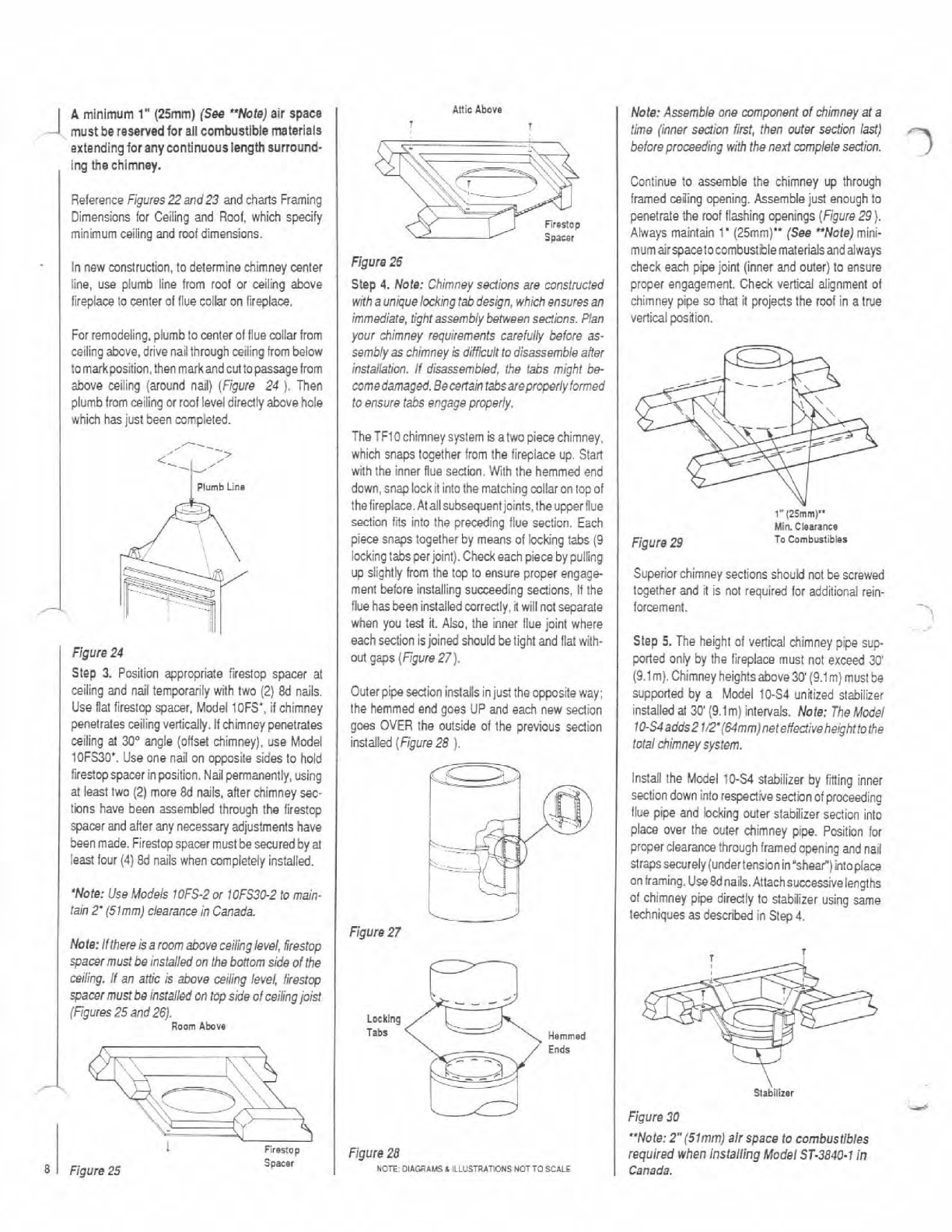
Nofe: Ifthereisaroomaboveceilinglevel,frestop
spacermustbe~nslalledon the bonomside ofthe
miling. Ifan altic is above ceiling level, lirestop
wacer must
be
installedon fopside of ceilingjoist
(Figures 25and26).
Room
Abova
%FR
.--
I
SreIlop
Spacer
8
Figure
25
AUic
Abovo
?
I
Figura26
Step
4.
Nola: Chimney sedions are mnst~cted
wilhauniquelockmgtabdesign, whichensuresan
immediate,tight assemblybehensect;ons. Plan
your chimney requirements careful) belore as-
sembly
as
chimney
k
difficultto disassembleah
installation. If disassembled, Vle tabs might be
mmedamaged.Becenalntabsareproperlyformed
to ensure tabs engageproperly.
The TFlO chimney system is atwopiecechimney.
which snaps together from the lireplace up. Stan
with the inner flue sedion. With the hemmed end
down,snap lock
it
into the matching collaron top ol
thetireplace.Atailsubsequentjoints,theupper
flue
section lits into the preading flue section. Each
piece snaps together by means of bckingtabs
(9
iockingtabsperjoint).Checkeachpiece by pulling
up slightly from the top to ensure proper engage
ment beforeinstallingsucceeding sedions, I1the
lluehasbeeninslalledmrredly,
I
willnot separate
when you test it. Also, the inner llue joint where
each sectionisjoined shouldbelight andllatwith-
out gaps (Figure27).
Outerpipesectioninstallsinjust the opposite way:
the hemmed end goes
UP
and each new sedion
goes OVER the outside of the previous sedion
installed(Figure28
).
A
minlmum 1" (25rnrn)
(Sm
"Note) air
spacs
mustberesewedfor allcornbustlblematerials
extendingfor anycontinuouslength surround-
Figure
n
-
-
Locking
Tabs
ing the chimney.
ReferenceFigures22and23 and chMs Framing
Dimensions lor Ceiling and Rwl, which spedly
minimum ceiling and root dimensions.
Innew mnstruction, to determine chimney center
line, use plumb line from rwl or ceiling above
lireplaceto center of flue colbr on lireplace.
Forremodeling,plumbto center ol lluecollar lrom
ceilingabove, drivenailthroughceilingfrombelow
tomarkposition,thenmarkandcut
topassagelrom
above ceiling (around nail) (Figure 24
).
Then
plumblromceilingor roofleveldiredlyabove hole
which has just been mmpieted.
2---_
,
plumb
line
Figure
28
NOTE:
DibGRbUSL
ILLUSTRAWNS
NOTTO
SCLLE
Figure
24
Step
3.
Position appropriate lirestop spacer at
ceiling and nail temporarily with two
(2)
8d
naiis.
Use llat lirestqspacer. Model IOFS',
il
chimney
penetralesceiling verlically. Ifchimneypenetrales
ceiling al
30"
angle (ollset chimney), use Model
10FS30'.Useone nail on opposite sides to hold
firedqspacer inpasition. Nailpermanently,using
at ieast two
(2)
more 8d nils, atier chimney sec-
tions have been assembled through the firestop
spacer and after any necessaryadjustments have
beenmade.Fireslopspacermust
be
searredbyal
least lour
(4)
8d nails when mmpleteiy installed.
'Note: UseModels IOFS-2or 10FS30-2to main-
tain
2'
(51mm) clearanceinCanada.
Note: Assemble one componentof chimney
at
a
tfme (innef sedion first, then outw
sec!ion
Id)
beloreproceedingwith the nextmmpletesection.
3
Continue to assemble the chimney up through
framed ceiling opening. Assemblejust enoughto
penetratethe rwlflashingopenings (Figure
29).
Always maintain
1'
(25mm)" (See "Note) mini-
mumairspacetocombustbiematerialsandalways
check each pipejoint (inner and outer)to ensure
proper engagement. Check vertical alignment ol
chimney pipe
so
that it projedsthe rwlin a true
verticalposi(ion.
.
1"
(ZSmrn)"
Min
Cloaranr*
Figure
29
To
Comburtib$s
Superiorchimney sections should not be screwed
together and it is not requiredlor addiiiond rein-
forcement.
-..
~ ~
Step
5.
The height of vertical chimney pipe sup-
ported oniy by the fireplace must not exceed
3B
(9.lm). Chimney
heightsabove30'(9.lm)must
be
supported by a Model 10-54 unitized stabilizer
installedal
30'
(9.lm) intervals. Note:
The
Modei
10-S4adds2
ln'(64mm)neteflecrivehe~htto
the
totalchimneysystem.
install the Model
10S4
stabilizer by iming inner
sectiondown into respeaivesedion01proceeding
llue pipe and bcking outer stabilizer section into
place over the outer chimney pipe. Posilbn for
properclearancethrough framedopening and nail
strapssecurely(undertensionin'shear") intoplace
on framing.
Use8dnails.Attachsuccessivelengths
ol chimney pipe diredly lo stabilizer using same
lechniques as described in Step
4.
\
Stabilizer
Figure30
"Note:
2"
(51mm) air space lo combusfibles
requiredwhen InstallingModelST-3840-1
in
Canada.