SuperOn SER-H410A User manual

1
○
SER-H410A
4CH H.264
DVR
User Manual
This document contains preliminary information and subject to change without prior notice.
SER-H410A v1.0

2
This symbol is intended to
alert the user to the presence
of unprotected “Dangerous
voltage" within the product's
enclosure that may be strong
enough to cause a risk of
electric shock.
This symbol is intended to
alert the user to the presence
of important operating and
maintenance (servicing)
instructions in the literature
accompanying the appliance.
WARNING
TO REDUCE THE RISK OF FIRE OR
ELECTRIC SHOCK, DO NOT EXPOSE
THIS APPLIANCE TO RAIN OR
MOISTURE.
NOTE: This equipment has been tested
and found to comply with the limits for a
class digital device, pursuant to part 15 of
the FCC Rules. These limits are designed
to provide reasonable protection against
harmful interference when the equipment is
operated in a commercial environment.
This equipment generates, uses, and can
radiate radio frequency energy and, if not
installed and used in accordance with the
instruction manual, may cause harmful
interference to radio communications.
Operation of this equipment in a residential
area is likely to cause harmful interference
in which case the user will be required to
correct the interference at his own expense.
Disposal of Old Electrical & Electronic Equipment (Applicable in the European
Union and other European countries with separate collection systems)
This symbol on the product or on its packaging indicates that this product shall not be treated
as household waste. Instead it shall be handed over to the applicable collection point for the
recycling of electrical and electronic equipment. By ensuring this product is disposed of
correctly, you will help prevent potential negative consequences for the environment and
human health, which could otherwise be caused by inappropriate waste handling of this
product. The recycling of materials will help to conserve natural resources. For more detailed
information about recycling of this product, please contact your local city office, your household
Caution
RISK OF ELECTRIC
SHOCK DO NOT OPEN
CAUTION: TO REDUCE THE RISK OF
ELECTRIC SHOCK, DO NOT REMOVE COVER
(OR BACK). NO USER SERVICEABLE PARTS
INSIDE. REFER SERVICING TO QUALIFIED
SERVICE PERSONNEL.

3
Table of Contents
CHAPTER 1 PACKING DETAIL AND INSTALLATION........................................................... 5
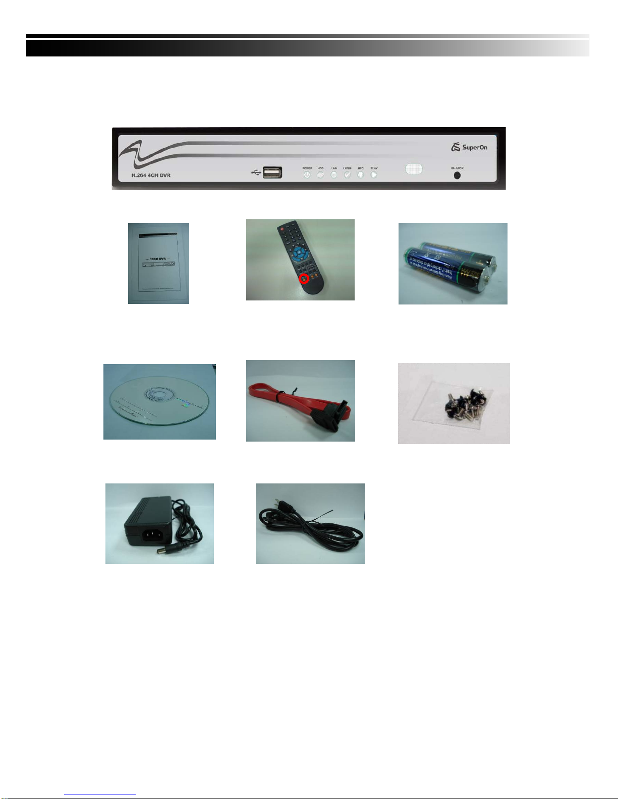
1-1 PACKING ..................................................................................................................... 5
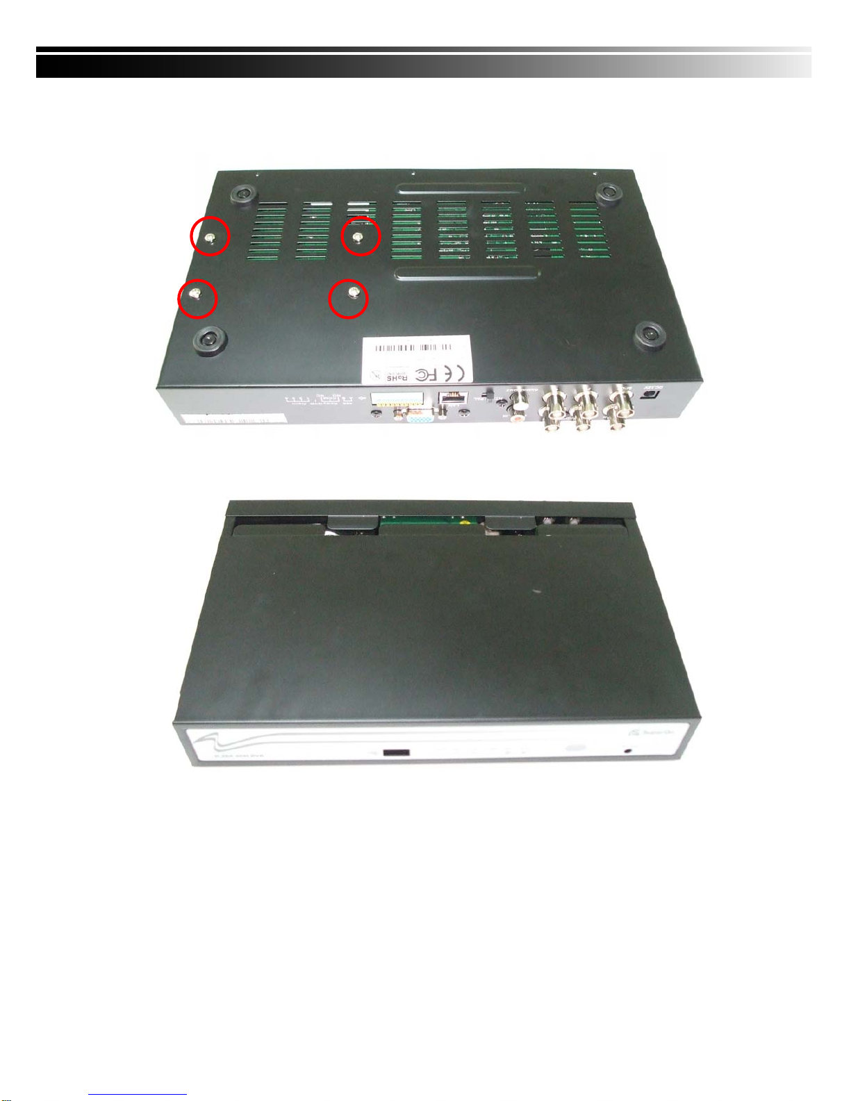
1-2 Hard Disk Installation................................................................................................... 6
CHAPTER 2 PANEL LOCATION............................................................................................... 8
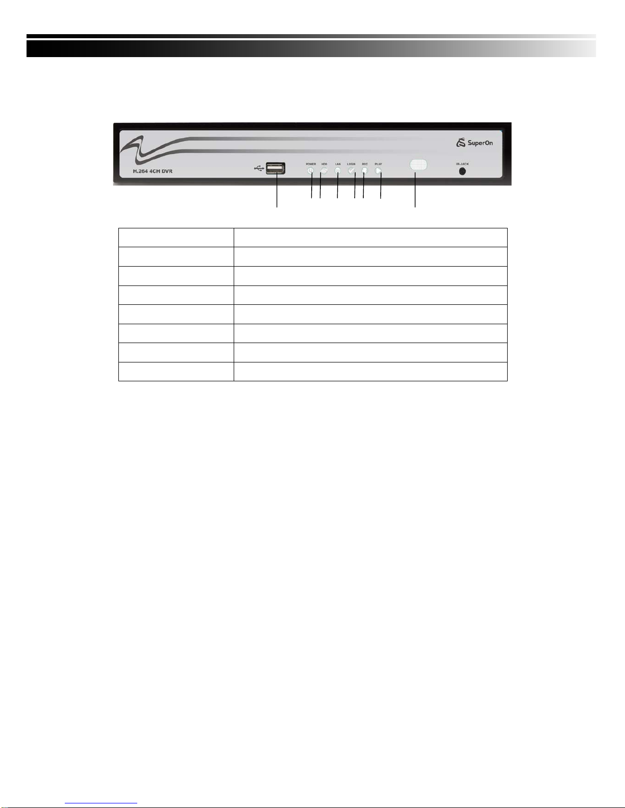
2-1 FRONT PANEL CONTROLS ....................................................................................... 8
2-2 4CH REAR PANEL CONNECTORS............................................................................ 9
CHAPTER 3 LIVE, PLAYBACK AND PTZ OPERATIONS ................................................... 10
3-1 LIVE Mode.................................................................................................................. 10
3-2 PLAYBACK Mode....................................................................................................... 13
3-3 PTZ Mode................................................................................................................... 15
CHAPTER 4 MAIN MENU SETUP....................................................................................... 17
4-1 RECORD SETUP....................................................................................................... 18
4-1.1 Quality & Frame Rate Setup _____________________________________ 19
4-2 EVENT SETUP .......................................................................................................... 19
4-2.1 MOTION SETUP ______________________________________________ 20
4-2.1.1 MOTION AREA SETUP
____________________________________________ 21
4-2.2 SENSOR SETUP______________________________________________ 22
4-3 SCHEDULE SETUP................................................................................................... 23
4-3.1 Schedule Record Setup_________________________________________ 23
4-3.2 Holiday Setup ________________________________________________ 24
4-4 CAMERA SETUP....................................................................................................... 24
4-5 ACCOUNT SETUP..................................................................................................... 25
4-5.1 Permission Setup______________________________________________ 26
4-6 NETWORKING SETUP ............................................................................................. 26
4-6.1 NETWORKING SETUP_________________________________________ 27
4-6.1.1 DHCP
____________________________________________________________ 27
4-6.1.2 LAN
______________________________________________________________ 27
4-6.1.3 ADSL
___________________________________________________________ 28
4-6.2 HTTP SETUP_________________________________________________ 28
4-6.3 DDNS Setup ________________________________________________ 29
4-6.4 Mail Setup__________________________________________________ 29
4-7 PTZ & RS485 SETUP................................................................................................ 30
4-8 SYSTEM SETUP ....................................................................................................... 31
4-8.1 DISPLAY SETUP______________________________________________ 32
4-8.2 DATE/TIME SETUP____________________________________________ 32
4-8.2.1 CHANGE DATE & TIME
__________________________________________ 33
4-8.2.2 TIME ZONE SETUP
_______________________________________________ 33
4-8.2.3 INTERNET TIME SETUP
___________________________________________ 34
4-8.3 BUZZER & RELAY SETUP ______________________________________ 34
4-8.4 SPOT SETUP ________________________________________________ 35
4-9 UTILITY SETUP......................................................................................................... 36
4-10 DIAGNOSTIC........................................................................................................... 37
CHAPTER 5 BACKUP & SEARCH....................................................................................... 38
5-1 BACKUP SETUP........................................................................................................ 38
5-2 SEARCH SETUP....................................................................................................... 39
5-2.1 EVENT SEARCH______________________________________________ 39
5-2.1.1 CRITERIA SETUP FOR EVENT SEARCH
____________________________ 40
5-2.2 TIME SEARCH _______________________________________________ 41
CHAPTER 6 NETWORK SURVEILLANCE.......................................................................... 42
6-1 AP Software Installation and Setup............................................................................ 42
6-2 AP Software Operation............................................................................................... 44
CHAPTER 7 SPECIFICAITONS........................................................................................... 46
CHAPTER 8 MOBILE APPLICATION INSTALLATION AND USAGE..................................... 48
8-1 Mobile Application Installation and Operation for Symbian System........................... 48
8-1.1 Mobile Application Installation ____________________________________ 48
8-1.2 Mobile Application Operation_____________________________________ 49

4
8-1.2.1 Add New Login DVR
______________________________________________ 49
8-1.2.2 Logging Onto the DVR
_____________________________________________ 49
8-1.2.3 Modify the Login Information of DVR
________________________________ 50
8-1.2.4 Delete the Login Information of DVR
________________________________ 50
8-1.3 Live Monitoring Operation _______________________________________ 51
8-1.3.1 Scroll the Image
___________________________________________________ 51
8-1.3.2 Image Quality Setup
________________________________________________ 51
8-1.3.3 Channel Display
____________________________________________________ 51
8-1.3.4 Size of Image
_____________________________________________________ 52
8-1.3.5 Rotate the image
___________________________________________________ 52
8-1.3.6 Alarm
_____________________________________________________________ 52
8-2 Mobile Application Installation and Operation for Windows Mobile System.............. 52
8-2.1 Mobile Application Installation ____________________________________ 53
8-2.2 Mobile Application Operation_____________________________________ 54
8-2.3 Operation under the LIVE monitoring. ______________________________ 54
8-2.3.1 Operation under the LIVE monitoring for Jrviewer
_____________________ 55
8-2.3.2 Operation under the LIVE monitoring for H264 Pocket
_________________ 56
CHAPTER 9 CMS INSTALLATION AND USAGE GUIDE....................................................... 57
9-1 CMS Installation......................................................................................................... 57
9-2 CMS LOGIN AND ENVIRONMENT........................................................................... 61
9-3 DVRs, Groups & Events............................................................................................. 62
9-3.1 View DVR
/
Group List _________________________________________ 62
9-3.2 View Event Logs ______________________________________________ 62
9-4 Local PC Information and Control.............................................................................. 63
9-5 Main Display............................................................................................................... 63
9-5.1 Audio Control_________________________________________________ 63
9-5.2 eMAP Display ________________________________________________ 64
9-5.3 PTZ Control __________________________________________________ 65
9-6 Operation Bar............................................................................................................. 66
9-6.1 User administration ____________________________________________ 67
9-6.2 DVR Administration ____________________________________________ 67
9-6.3 Group Administration___________________________________________ 68
9-6.4 eMap Administration ___________________________________________ 69
9-6.5 Remote Play _________________________________________________ 69
9-6.6 HDD Playback ________________________________________________ 70
9-6.7 File Playback _________________________________________________ 71
9-6.8 Event Playback _______________________________________________ 72
9-6.9 Snapshot Data________________________________________________ 73
9-6.10 Recording Data ______________________________________________ 73
APPENDIX I -DVR.NRT REGISTRATION............................................................................... 74
APPENDIX II Record Mode Comparison ................................................................................ 76

5
CHAPTER 1 PACKING DETAIL AND INSTALLATION
1-1 PACKING
1. DVR
3. IR Remote Controller
*Please press “DVR1”
button before operation
7. Screws x4
9. Power Cord
4. Batteries x2
2. Quick Start
6. SATA Cord x1
8. Power Adaptor
5. CD

6
1-2 Hard Disk Installation
Step 1) Remove the 3 screws from DVR as cycled below.
Step 2) Remove the front cover from DVR as indicated by the arrow.
Step 3) Place the HDD on the HDD plate and connect the power and the
SATA cables.

7
Step 4) Screw the bottom of the DVR as indicated as cycled.
Step 5) Place the bottom of DVR and screw.

8
CHAPTER 2 PANEL LOCATION
2-1 FRONT PANEL CONTROLS
○
1USB 2.0 Port Port for USB external devices.
○
2LED Display-Power DVR Power is on.
○
3LED Display - HDD Hard disk is in use.
○
4LED Display - LAN Connected to the internet.
○
5LED Display-LOGIN Remote user logged in.
○
6LED Display - REC DVR Recording.
○
7LED Display - PLAY DVR Playing back.
○
8IR Sensor Input sensor for the remote controller.
○
4○
6○
7○
8
○
1○
2○
3○
5

9
2-2 4CH REAR PANEL CONNECTORS
○
1DC 12V Socket for a DC 12V input.
○
2SPOT monitor BNC port to display full screen image of all installed cameras in
sequence.
○
3MAIN monitor BNC port for the main monitor.
○
4VIDEO IN 4 x BNC input ports for cameras
○
5AUDIO IN RCA input port for audio signal.
○
6AUDIO OUT RCA output for audio signal.
○
7NTSC/PAL Switch Switch between NTSC and PAL format.
○
8 LAN Network port.
○
9VGA VGA port.
⑩ EXTERNAL I/O EXTERNAL I/O port (see below for pin definition)
○
2○
6○
7○
8⑩
○
4
○
1③○
9○
5

10
CHAPTER 3 LIVE, PLAYBACK AND PTZ OPERATIONS
3-1 LIVE Mode
You can monitor all the channels, listen to audio signal and have some related operations under
LIVE mode. This paragraph describes the IR remote controller, mouse operation and on screen
graphical icons under LIVE mode.
Table 3-1.1 Functions of remote controller under LIVE mode
Button Description
REC Start/Stop recording.
PLAY Start playing back the most recently recorded segment.
LOCK Enable/Disable the Keypad function
1,2,3,4 Select the channel to monitor in full screen
FREEZE Turn on/off screen freeze function.
Switch to quad display.
Switch to 9-channel display. 4ch DVR doesn’t feature this function.
Switch to 13-channel display. 4ch DVR doesn’t feature this function.
Switch to 16-channel display. 4ch DVR doesn’t feature this function.
ENTER/MODE Switch to full screen, quad display.
MENU/ Enable/ Disable setup Menu.
BK-UP/ESC Enable/ Disable backup menu.
SRH Enable/ Disable search menu.
MUTE Switch channel 1 output audio / turn off LIVE audio
STATUS Enable/ Disable Status.
OSD Turn on/off the screen display
Zoom/Zoom - Enable/ Disable double screen size display. You can click on the channel
name for choosing a specific channel.
PIP/Zoom + Turn on picture-in-picture format. Click on the channel name can switch to
other channels.
PTZ Enable PTZ control.
AUTO InAUTO mode, all available channels will be cycled through in full screen.
DVR1,2,3,4 Switch DVR ID1~4

11
Table 3-1.2 Graphical icons that will display after right-clicking your mouse under LIVE mode.
Icon Description
Resting the cursor on this icon will bring up the following
four menu icons.
Main MENU
SEARCH menu
BACK-UP menu
PTZ mode
Turn on/off recording.
Playback.
Resting the cursor on this icon will bring up the following
five display icons.
FREEZE
PIP, picture in picture
ZOOM
AUTO sequence
LOCK
Full screen display
Quad display

12
Table 3-1.3 Description of on screen graphical icons in LIVE mode
Icon Description
Recording is on
LIVE Audio is on
LIVE Audio is off
Motion detected on the channel
Sensor triggered on the channel
Video loss detected on the channel
USB device detected
Remote user currently logging into DVR.
Timer recording is on.
Red:Timer is set and recording has been started.
White:Timer is set but recording has not yet been started.
AUTO-seq is on.
2X 2X zoom-in is on.
Freeze is on, screen is frozen.
LOCK is on.
PTZ control is on.
1~8
Remote control can be set from 1-8, meanwhile, ID of each
remote controller needs to match up with DVR to be able to
control it. (DVR default set up ID is 1.)

13
3-2 PLAYBACK Mode
Switch to PLAYBACK mode by pressing “PLAY” under the LIVE mode, the graphical icon
will show up on the upper center of the screen and the operation panel ( see below picture) will
show up at right lower corner of the screen. You can drag the panel by mouse to place it on
any location of your screen.
Table 3-2.1 Remote controller functions under the PLAYBACK mode
Button Description
ENTER / MODE Switch to full screen, quad, 9-channel or 16-channel display.
MENU / Turn on/off PAUSE.
PLAY Play back at normal speed.
/SLOW Play back at slower speed. The speed will be slowed to 1/2, 1/4, 1/8,
1/16 by each pressing of the button till the slowest limitation of 1/16 of
the normal speed. Current playback speed is shown in the upper
center of the screen.
/ Fast rewind. Each press increases the speed to the next level. There
are six speeds: 2x, 4X, 8X, 16X, 32X and 64X.
/ Fast forward. Each press increases the speed to the next level. There
are six speeds: 2x, 4X, 8X, 16X, 32X and 64X.
/ Stop playback.

14
Table 3-2.2 The mouse operation under the PLAYBACK mode.
Icon Description
「/ 」Fast rewind
「/ 」Fast forward
/ Play / pause
「▲/SLOW」,slow playback
「▼/ ■」stop
「▌▌」pause playback
Full screen display
Quad display

15
3-3 PTZ Mode
Switch to the PTZ mode by pressing “PTZ” button under the LIVE mode. The PTZ icon
will appear on upper left of the screen.
Table 3-3.1 Remote Controller functions under the PTZ mode
Button Description
/SLOW Move PTZ up.
/ Move PTZ down.
/ Move PTZ to the left.
/ Move PTZ to the right.
ZOOM + PTZ zoom-in.
ZOOM - PTZ zoom-out.
FOCUS + PTZ focus-in.
FOCUS - PTZ focus-out.
IRIS + PTZ iris-open.
IRIS - PTZ iris-close.
TOUR Activate PTZ pre-set tour. *
PRESET To go to a preset location, press PRESET and a number key. DVR will save
the current location.
PRESET +
NUMBER To go to a preset location, press PRESETand a number key. DVR will save
the current location.
PLAY +
NUMBER Move to a preset location, press PLAY and a number key. DVR will move to
the current location.
PIP Set current PTZ location as the start of the line-scan. *
FREEZE Activate line-scan. *
ZOOM Set current PTZ location as the end of the line-scan. *
*PTZ communication protocols from different brands aren’t compatible 100% sometimes.
Therefore, some of these functions may be unavailable.

16
Table 3-3.2 Mouse operation under the PTZ mode
Icon Description
Leave PTZ Mode, back to the LIVE mode.
Pre-set number N.(1~64)
Go to pre-set number N.
Set PTZ at N.
「TOUR」pre-set locations in order.
Set current location as the beginning for patrol
line scan.
「AUTO」auto patrol line scan.
Set current location as the end of patrol line s
can.
To move PTZ in 360。
PTZ zoom in; PTZ zoom out.
PTZ focus in; PTZ focus out.
PTZ IRIS open, PTZ IRIS close.
Below functions need specified PTZ support. Please see each PTZ s
et up.
AUX 1。
AUX 2
AUX 3
AUX 4
AUX 5
AUX 6
AUX 7
AUX 8
Customized「Backup」

17
CHAPTER 4 MAIN MENU SETUP
To enter the main menu and set up DVR, log-in account and user password are required.
The default password of the administrator is “123456”. Please check the “Account Setup” for
related setup of other log-in users.
Table 4-0.1 Some definitions of virtual keyboard.
Item Description
Switch between capital and small letters.
/ Switch between numbers and letters.
Press to cancel the setup, and re-choose the login
account.
Delete the last character.
Enter to identify the password. It will enter the set
up menu, If the password is verified.

18
Table 4-0.2 The operation of remote controller under the setting menu
Item Description
Switch to different options under one item
Switch to different items
MENU Save setup and back to LIVE mode
ESC Back to Upper level of the menu
ENTER Enter the menu, or display virtual keyboard
PS. The initialization of new-installed HD is required before recording, please refer to “4-9 UTILITY SETUP” for detail.
4-1 RECORD SETUP
Item Description
HDD FULL
Select STOP to stop recording or OVERWRITE to reuse the HDD
when HDD is full
「Stop」:Stop Recording
「Overwrite」:Start to overwrite that begin from the oldest data of
HDD, and continue to record.
Record Normal Enable/Disable normal recording
Pre Alarm Record Enable/Disable pre-event recording while motion or sensor is
triggered but not in the recording mode. This option decides if save
the pre-recording time 10 seconds data or not.
Audio Record Enable/Disable Audio recording.
Record Motion Enable/Disable recording while Motion is detected
Record Sensor Enable/Disable recording while Sensor is triggered
Video Preservation Setup the video preservation period. Recorded video will be
deleted automatically after expiry of preservation period.
Quality & Frame
Rate Setup
Setup the quality and frame rate for each channel under nor
mal recording and event recording type.

19
4-1.1 Quality & Frame Rate Setup
Item Description
Resolution Choose record resolution from : CIF / HD1(2CIF) / D1.
Record Type You can setup quality and FPS separately for record type.
No. Check/uncheck the box will enable/disable recording of that channel.
Quality Choose from Lowest/ Low/ Normal/ High/ Highest
FPS Choose recording frame rate.
4-2 EVENT SETUP
Item Description
Alarm Duration (Seconds) Set up alarm duration in seconds.
Drag the white bar or press ◀ ▶ to adjust value.
Motion Setup Enter to set up motion detection
Sensor Setup Enter to set up sensor detection

20
4-2.1 MOTION SETUP
Item Description
Motion Detection Check the box to Enable/Disable Motion Detection for all
channels.
Motion Popup Check the box to Enable/Disable popup screen function for all
channels. When motion is detected in LIVE mode, the
detected channel image will pop up in full screen display.
1~4 You can setup independently for each channel.
Selected Channel Turn Check the box to Enable/Disable motion detection for each
channel.
Object Size
Drag the white bar or press ◀ ▶ to set up Object Size
from value 1 to 15 for each channel. The lower value
you set the higher sensitivity it will be.
Sensitivity Drag the white bar or press ◀ ▶ to set up Sensitivity from
value 1 to 15 for each channel. The lower value you set
the higher sensitivity it will be
Motion Area Setup Enter to setup motion detection area
Table of contents
Popular DVR manuals by other brands

JVC
JVC SR-DVM700ER instructions

KGuard Security
KGuard Security Aurora Series user manual

Menzel MVSS
Menzel MVSS MZ3H-6AHD-2IPC user manual

ERNITEC
ERNITEC DigiOpG2 EDNS3000 Series Installation, programming, & user manual

XENO
XENO XDR5K4 Setup and user's manual

D-Link
D-Link mydlink DNR-202L Quick install guide

Prodigy
Prodigy PD-DVR4CD-500 Installation & operation

Speco
Speco D8WRSM Assembly instruction

Shining Technology
Shining Technology CitiDISK DV FW1256C Quick use guide

Speco
Speco DVR-16TS Series owner's manual

Sony
Sony SVR-3000 - Digital Network Recorder Upgrade instructions

DSE
DSE MV Series installation manual