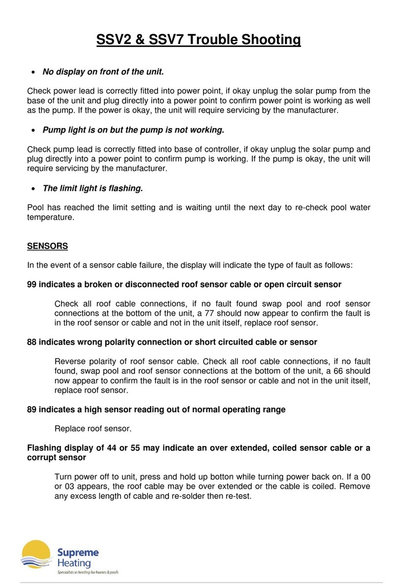
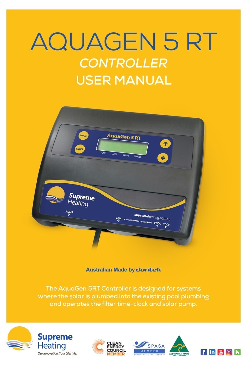
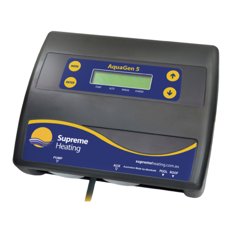
Supreme Heating Aqua-Gen 3BR Service manual

Aqua-Gen 3BR INSTRUCTIONS
INSTALLATION INSTRUCTIONS
CONTROLLER:
Find a suitable location to mount the control box*radio note. The controller must be installed out of direct
weather and no closer than 3m from the waters edge. Lift up the two mounting tabs and use two
appropriate screws to mount the control box to the wall, keeping in mind that the power cable is 1.8m
long and should be plugged directly into a general power outlet, not into an extension lead. Do not drill
through the box.
SOLAR PUMP:
The solar pump plugs into the left side 240Vac socket marked as PUMP.
TEMPERATURE SENSOR:
The pool temperature sensor must be fitted into the suction line of the solar pump, as close to the pool
as practical, preferably in a position out of direct sunlight. It is recommended that a 14.5mm hole be
drilled in the PVC pipe, this can be carried out using a Dontek PD01 grinding drill or a small pilot hole
can be drilled and a 14.0mm drill-bit used spinning in a counter clockwise direction to minimise the
chance of shattering pipe. Insert the grommet into the pipe and gently push in the black sensor barb.
The green sensor plug is to be fitted to the plug socket marked POOL, in some cases there is some
benefit to cable tie 30cm of wire from the pool temperature sensor to the pipe and insulate this section
(some ambient differences can travel up the tinned copper wire and affect the sensor reading).
All temperature sensor cables must NOT be run parallel to power cables and should never be
cable tied to power cables. All cable run lengths should be less than 50m if possible. Cable ties
should be used to fasten the sensor cable to the cold water inlet pipe making sure that the ties are
approximately 10mm from PVC fittings. Cable ties should be tightened only firm, over tightening can
cause breaks in the outer PVC if not careful. If the cable is to be run under ground a conduit must be
used to protect the wire and there is to be no cable joins within, conduit ends must be sealed to
prevent water ingress. Any excess cable should be removed and re-fitted ensuring that the wire
ends are tinned with solder.
REMOTE TEMPERATURE ROOF SENSOR:
The roof temperature sensor must be fitted into a small piece of solar collector or equivalent and
attached to the roof. The best location is within an arms length of the gutters edge of the house or
shed as long as the sensor end is not shaded and is on a roof of similar aspect of the main collector. It
must not be fitted on top of the solar collector or fitted to high points on the roof like Ridge Capping as
false readings will be detected.
This unit has been designed to eliminate the need to run a temperature sensor cable from the solar
controller to the roof; this is replaced by a battery powered transmitter that transmits the roof
temperature. The roof sensor plugs into the radio remote temperature transmitter socket at the bottom
of the unit (run the cable behind the box).

Fit the radio remote temperature transmitter with 4xAA alkaline batteries and mount it to a nearby solid
fixture*radio note by either the two mounting lugs or direct attachment though the controller. The
transmitter must be installed out of direct weather and no closer than 3m from the waters edge. Mount
the unit so battery replacement is possible without needing a ladder (antenna points UP).
*RADIO NOTE: RADIO TRANSMITTER SPECIAL CONSIDERATIONS:
Do not permanently fix the radio transmitter until good reception is achievable (see site test). Do not
mount the Aqua-Gen 3BR in a position where reception of radio signals may be difficult, avoid
mounting near other electrical equipment (try a site test with a FM radio or mobile phone).
The range is 100m with no obstructions and with no interference from other transmitters or sources of
electrical noise. Transmission may not occur through objects such as steel, aluminium, re-enforced
concrete and large bodies of water (e.g. pump room under a pool). Line of sight is the ideal situation
but not always possible, the antennas should always remain vertical. Echo cancellation or ghosting
may occur, which will prevent the signal being received reliably. If the Aqua-Gen 3BR is to be installed
in a metal shed there may be reception issues and the controller may need to be optioned with a
remote antenna or moved outside.
SITE TEST:
Place the radio transmitter in the approximate location, open the unit and select test mode by
removing the small plug from the RUN position from the 3 pin header and placing it onto TEST. The
Aqua-Gen 3 BR will enter into a RX TEST mode. Verify that every 8-9 seconds the LCD displays the
temperature (e.g. TEST 32°) followed about 3 seconds later by the test mode transmission (RSSI xx).
Check that this sequence is repeated for about half a minute and ensure no transmission is missed. If
a transmission is missed it may be due to an echo or ghosted signal, move the location of the radio
transmitter or Aqua-Gen 3BR and re-test. If no transmission is missed mount the transmitter and
repeat the test, check that no transmission is missed for 2 minutes.
Turn OFF power to the Aqua-Gen 3BR and then set the radio transmitter to operating mode by
removing the small plug from TEST and set it to RUN. Return to the Aqua-Gen 3BR and ensure it
receives the transmission. When RUN mode is selected a single transmission occurs after 30 seconds
followed by another transmission 30 seconds later, after the 2 transmissions the unit will only transmit
every 6 minutes to conserve battery power. (When the batteries are inserted there are also 2
transmissions, the first transmission is instantaneous, the second transmission occurs after 30
seconds.)
If required the Aqua-Gen 3BR can be forced into RX TEST mode by holding the DOWN button on
power-up for 3 seconds, RX TEST is displayed once the DOWN button is released.
During normal operation the software allows for missed transmissions, but when more than 50
minutes elapse without a transmission then the temperature value will timeout and will be indicated by
the “waiting for roof transmission” message.
IF LEFT IN TEST MODE, BATTERY LIFE WILL BE LESS THAN 1 WEEK!

REPORTED TRANSMITTER FAULTS:
If the following messages are displayed, then action is to be taken to rectify the fault(s).
"WAITING FOR ROOF TRANSMISSION"
The Aqua-Gen 3BR cannot receive a roof temperature from the radio transmitter or more than 50
minutes have elapsed since the last transmission, check installation is per instructions & check battery
conditions.
"TRANSMITTER IS IN TEST MODE"
The radio transmitter has been left in test mode, the Aqua-Gen 3BR will not operate instead it will
enter into a RX TEST loop, this is to aid installation only, rectify by removing the small plug from TEST
and place it onto RUN.
"TRANSMITTER BATTERIES ARE FLAT"
The radio transmitter batteries have expired; this will prevent the controller from operating. Replace
batteries and re-select any operating mode to clear the battery low message.
Note: Batteries may begin to leak before they expire, therefore it is recommended to replace the
batteries once per year.
"ROOF SENSOR DISCONNECTED OR OPEN CIRCUIT"
Check that the temperature sensor is firmly connected to the terminals. If the cable has been trimmed
ensure the ends have been tinned with solder. Cable joints must also be soldered and sealed
(preferably with heat-shrink). An unbroken but damaged cable can also cause this fault.
"ROOF SENSOR SHORT CIRCUIT OR REVERSED"
If the cable has been joined or shortened be aware that the white side of the cable is positive, inside
the transmitter there is a white + on the green board indicating where positive is to be connected.

OPERATING INSTRUCTIONS
DESCRIPTION:
The Aqua-Gen 3BR is a premium automatic solar controller with temperature adjustment, manual,
winter and tropical mode features.
TEMPERATURE LIMIT:
The controller will automatically choose to run the pump based on solar gain (i.e. sun shining & roof is
hot), once the desired temperature is achieved the pump is stopped and a 4 hour wait commences to
ensure no energy is wasted by cycling the pump.
If after 4 hours the roof is hot enough then the pump may start to provide another heating cycle and if
the desired temperature is reached again then no heating will occur until the next day unless the
controller is operating in time-clock mode where heating can occur until solar lockout time (09:00 until
19:00).
MODE of operation:
Pressing the SELECT button once will display the current mode of operation, pressing it again or
holding it will select the next available mode of operation.
The available modes are SUMMER, MANUAL, WINTER, TROPICAL and SETTINGS.
Summer mode is the normal operating mode for heating the pool.
Manual mode is for testing the pump installation on a cold or cloudy day. Once manual mode is
selected the pump will start if it has been off, or stop if it has been on (running). After 30 minutes
manual mode will time-out and return to Summer Mode with a default temperature limit of 30°C.
Winter mode of operation is for off-season maintenance or if pool heating is not required (AWAY
MODE). This is a better option than turning off the controller as it will flush treated pool water through
the solar system as well as prolong pump bearing and mechanical seal life. The pump will run for 3
minutes each day from when the winter mode was selected or at 10am if the time-clock mode was
selected.
Tropical mode is for situations where the pool water overheats due to direct heating from the sun,
beyond the set limit. When the roof is 4°C cooler than the pool temperature, the pump is started (this
will most likely occur at night) and will attempt to cool the pool to 1°C above the temperature limit.
Normal heating will occur the next day if the pool drops below the temperature limit by 1°C.
Settings mode is for setting the unit into time-clock operation.
When you select this option you will be asked if you wish to use the clock feature (CLK? ON/OFF).
If you select OFF then the controller will not work as a time-clock model and will allow the solar pump
to run whenever there is solar heating available.

If you select ON you will be prompted to set the time of day, the controller will work in time-clock mode
and the solar pump is prevented from starting outside of the set hours (unless tropical mode is
selected).
Set the time of day in 24 hour format, note there is an AM/PM indication to avoid incorrect settings.
Seconds are automatically set to zero.
Once the time is set select the START hour from 6am until 12noon, default is 9am which means the
solar pump cannot start before 9am.
Now select the END hour from 15:00 (3pm) until 21:00 (9pm), default is 19:00 (7pm) which means the
solar pump will stop at 7pm.
INSTALLER SETTINGS - Adjustable differential and anti-freeze feature:
Special note: Adjusting these values to any setting other than the defaults may adversely affect the
performance of this controller.
To select these features, hold the DOWN button then press SELECT.
When you select this option you will be prompted to set the solar gain start temperature (RUN° x) this
setting allows the pump to start if the roof temperature exceeds the pool temperature by this value,
adjust with the UP/DOWN button, press SELECT to accept. Next you will be prompted to set the
differential hysteresis (END° x) which turns the pump off when roof temperature is less than the pipe
temperature plus this value, adjust with the UP/DOWN button, press SELECT to accept. Default
values are 8° for RUN and 4° for END, these are the optimal values for maximum efficiency, some
coastal locations may benefit from a reduced run value of 6°C for RUN and 4°C for END.
Next is anti-freeze, you will be prompted by FRZ? ON/OFF, adjust with the UP/DOWN button, press
SELECT to accept. If you select OFF then all the above settings will be saved and the unit will restart.
If you selected ON then you will be prompted to adjust the anti-freeze start temperature point as
follows; FREEZ° x adjust with the UP/DOWN button, press SELECT to accept.
Once the roof temperature gets to the anti-freeze setting or below then the pump will be turned on for
3 minutes then turn off for 30 minutes, this sequence will repeat until the roof temperature rises above
the anti-freeze temperature.
Once the advanced settings have been adjusted all the above settings will be saved and the unit will
restart. Re-adjust the temperature limit if required.
FACTORY TEST:
To run the factory test, hold the SELECT button when first applying power, the unit will perform a
series of self-diagnostic functions with the pump running.
If there are any faults they will be reported on the display before the unit restarts into normal operation.
Note: that this will force all settings to a factory default state. Re-enable time-clock if required also

reset the temperature limit and operating mode to their required settings.
NOTES:
1. If a sensor fault is detected the controller will display which sensor failed (POOL and/or ROOF)
and the type of failure.
2. After a power outage all configurable items are retained & the clock (if used) will keep time for up
to 14 days.
3. Temperature sensors used with this unit is digital and is accurate to 0.5°C, no calibration is
required.
4. The sensor cable with the thin trace is the positive and is fitted to the right hand side of the green
plug when looking at the plug screws, incorrect polarity will be displayed as a short circuit or
reversed fault.
5. If the controller has stopped pumping and is displaying a higher temperature than expected it
may be caused by a pump which is failing to prime, check the pump and if necessary prime the
pump as per the pump manufacturers’ instructions then reset the controller by turning it off/on.
6. Maximum total rated output load is 10 Amps 2400 Watt.

WARRANTY - Aqua-Gen 3BR
This range of product is covered by a limited 3 year warranty against component failure or faulty
workmanship from the date of installation.
A faulty unit should be returned in the first instance to the dealer from which the unit was purchased.
Damage to the unit due to misuse, power surges, lightning strikes or installation that is not in
accordance with the manufacturer’s instruction may void the warranty.
Warranty does not cover travel costs to or from installation site.
Return to supplier for repair
Customer Record (to be retained by the customer)
Dealer/Installer Name: _________________________________________________________
Model Number: Aqua-Gen 3BR ____
Serial Number: _________________________________________________________
Date Installed: _________________________________________________________
For service assistance phone 1300 130 693
Dontek Electronics Pty Ltd
PO Box 239
Bayswater, Victoria 3153
www.dontekelectronics.com.au
Return to Manufacturer for repair
Table of contents
Other Supreme Heating Controllers manuals
Popular Controllers manuals by other brands
IAI
IAI ROBO Cylinder RCS4- SA4C instruction manual

Telemark
Telemark 861 Quick setup

Emerson
Emerson Bettis Q series Installation, operation & maintenance manual
Grundfos
Grundfos VGA-113-110 Installation and operating instructions

Motoman
Motoman XRC instruction manual
VOLTCRAFT
VOLTCRAFT HygroCube 100 operating instructions
