Supreme Heating AquaGen 5 User manual
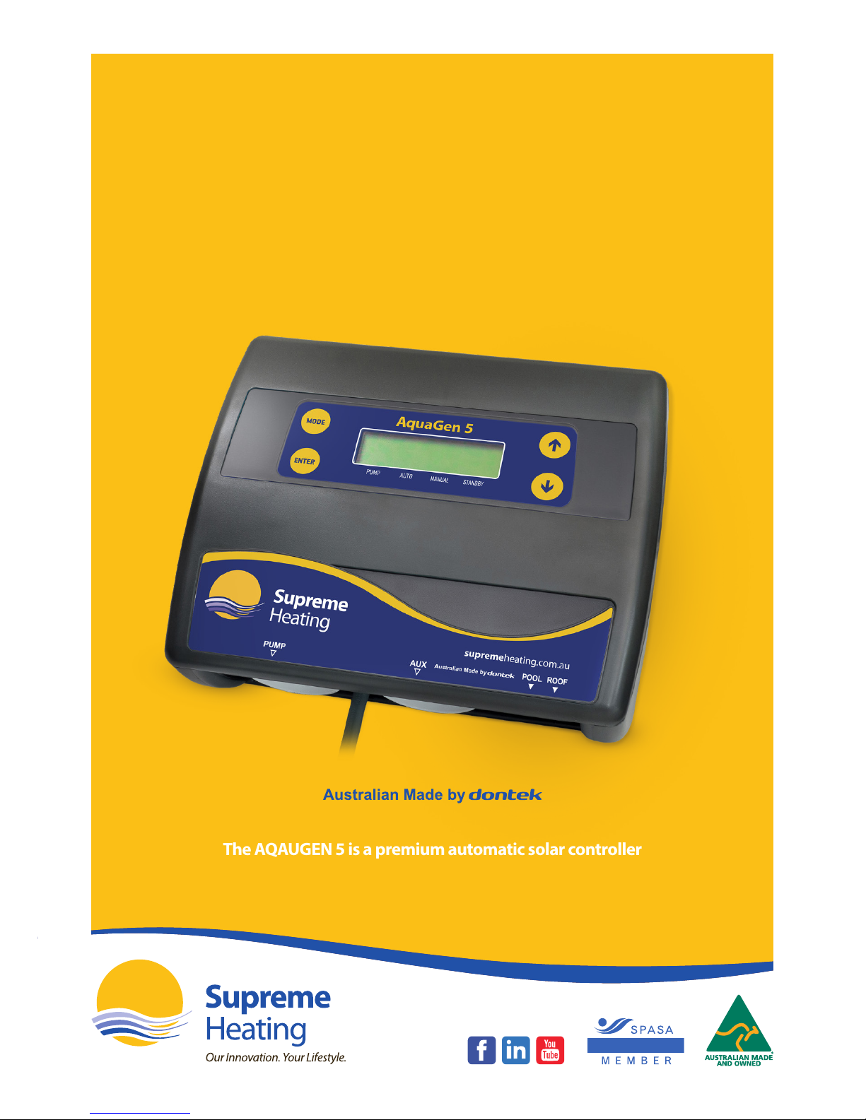
The AQAUGEN 5 is a premium automatic solar controller
with temperature adjustment, manual, cooling
and standby mode features.
NATIONAL
AquaGen 5
Controller
User Manual
AquaGen 5
Controller
2
Controller Mounting
Find a suitable location to mount the control box. Ideally as with all pool equipment it should be
installed out of direct weather and no closer than 3 meters from the water’s edge and a minimum
600mm above ground. Fix the mounting bracket to a solid structure and slide the controller on,
keeping in mind that the power cable is 1.8m long and should be plugged directly into a general
power outlet, not into an extension lead.
Pump Connection
The solar pump plugs into the 240V socket labelled PUMP. The maximum load is 9.98 AMPS at
2395W.
Pool Sensor
The pool sensor must be tted into the heating circuit, as close to the pool as practical, preferably
in a position out of direct sunlight. It is recommended that a 14.5mm hole be drilled in the side
of the PVC pipe (not the top of the pipe where water will collect). This can be carried out using a
Dontek PD01 grinding drill or a small pilot hole can be drilled with a 14.0mm drill-bit spinning in
a counter clockwise direction to minimise the chance of shattering pipe. Insert the grommet into
the pipe and gently push in the sensor barb. Ideally ~30cm of the cable from the sensor should
be tied to the shaded side of the pipe to prevent extreme ambient conditions leeching into the
sensor via the copper in the cable. The blue sensor plug is to be tted to the plug socket marked
POOL.
Roof Sensor
The roof sensor must be tted into a small piece of collector material away from the main
collector but on the same aspect, preferably no more than 50cm from the roof gutter (for ease of
sensor replacement). If required, the roof sensor can be on a dierent roof as the solar collector as
long as the alignment to the sun is similar to the solar collector. For encapsulated collector panels,
use the manufacturer’s instructions for roof sensor placement. The red sensor plug is to be tted
to the plug socket marked ROOF.
SENSOR NOTES: All excess cable must be removed; coils of cable are not permitted under any
circumstances and must not be tied to 240V wiring. If the cable is to be extended with non-
genuine cable a size of 14/020 should be used. Any cable joins should be soldered. Heat shrink
is to be used over soldered joints to eliminate moisture ingress, and the cable end is to be retted
to the plug sockets. Once cables have been correctly tted the unit can then be turned on.
Installation Instructions
This appliance is not intended for use by young children or inrm persons
without supervision. Please ensure that young children are supervised to
ensure that they do not play with the appliance.
AquaGen 5
Controller
3
Operating Instructions
Mode Button
Pressing this button changes to the next mode of operation in the following order;
Heating / Manual / Standby.
Once the mode button is no longer being pressed then the selected mode of operation is
automatically saved.
Heating mode (Auto) is the normal operating mode for heating the pool.
Manual mode is for testing the pump installation on a cold or cloudy day. Once manual mode is
selected the pump will start. After manual mode time-outs, unit will return to the previous mode.
Standby mode of operation is for o-season maintenance or if pool heating is not required. This
is a better option than turning o the controller as it will ush treated pool water through the
solar system as well as prolong pump bearing and mechanical seal life. The pump will run for 3
minutes each day at 10am.
The factory default for SOLAR MODE is Heating MODE
Temperature Setting (Up and Down Buttons)
Adjusting the temperature limit will allow the controller to heat the pool until the temperature
limit +½°C is achieved. Heating will then remain o until the sample wait period expires, if no
sample wait period is active the heating will remain o until the pool temperature drops ½°C
below the temperature limit setting. Due to rounding the actual heat may vary by up to ±½°C.
The ability to solar heat the pool will depend on weather conditions.
The factory default for SOL. LIMIT is 30°C

AquaGen 5
Controller
4
Enter Button
Pressing the (ENTER) button will turn on the LCD backlight, pressing the (ENTER) button
while the backlight is lit will enter the SETTINGS MENU;
The following will be displayed; 1) EXIT
The menu system can be navigated using the or buttons, all selectable and changeable
values will ash on the LCD screen. Press the (ENTER) button to accept the currently displayed
(ashing) item.
All menu items are shown below;
1) EXIT
2) CLOCK
3) SYSTEM
1) EXIT
Press (ENTER) on this menu to return to automatic operation.
2) CLOCK
When selecting the clock you will have to set the time of day. Set hours then minutes.
3) SYSTEM
System sub-menu;
EXIT
COOLING
LCD TIME
HOURS
SYSTEM SUBMENU
EXIT Press (ENTER) on this menu to return to automatic operation.
COOLING
For situations where the pool water overheats beyond the set temperature limit due to direct
heating from the sun.
NOTE that heating & cooling is only allowed during the allowable time if solar run hours have been selected
LCD TIME Adjust the number of seconds the backlight remains on after the time a button was pressed.
(Select NONE for always on.)
HOURS
For hours of solar operation (24hr Clock) First selecting the start time in hour intervals
(6:00 – 12:00) Then the end time (12:00 – 21:00)
Factory default for installer setup is run from 12:00-12:00 (24hrs).
LCD Screen
The LCD screen displays the pool and roof temperatures, solar temperature limit, pump on status,
on/o/locked-out status and the time of day & date (clock).
LCD Indicators
There are arrow icons on the LCD screen that point to current mode text on the label.

AquaGen 5
Controller
5
Controller Troubleshooting
No Power To The Display
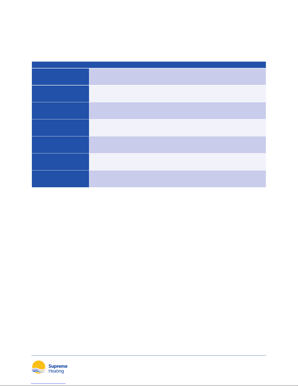
FAULT REASONS/SOLUTIONS
NO POWER TO THE
DISPLAY
Power point is faulty; test power point with known working appliance. If the power point
is operational, check the controller with another power point and if there is still no display,
then send the controller for repair.
Pipe/Roof Sensor Faults
The following are error messages caused by pool or roof sensor faults;
FAULT REASONS/SOLUTIONS
SENSOR DISCONNECTED Sensor cable unplugged from controller, cable damaged, bad cable join.
SENSOR SHORT CIRCUIT Sensor cable damaged, bad cable join.
ISOLATING
SENSOR FAULTS
Swap the sensor locations; simply put the pipe sensor in the roof socket and the roof sensor
in the pipe socket.
If the fault moves from pipe to roof or vice versa, then you can be certain that there is a
sensor fault. If the fault remains the same then the controller will need repair.
For sensor disconnected or short circuit faults, check for damage to the cable and repair if
required. If no damage can be found, replace the sensor. If the cable runs underground or
inspection is not possible, then cut the sensor from near the end of the cable and strip back
the wires and join them. If the controller reports a short circuit, then the cable is ne and you
may replace the sensor end if re-routing a new cable is not possible.
If the controller reports a short circuit while the cable is unplugged, then the controller
requires repair.

AquaGen 5
Controller
6
Pump Faults
Ensure the controller has working sensors; otherwise the pump will not operate.
FAULT REASONS/SOLUTIONS
PUMP WILL NOT START
The pump will only ever run for the purpose of automatic heating if the pool is below the
temperature limit and solar conditions can provide heating. The pump may also run for a
ush in standby mode or for manual mode operation. If the controller reports that the pump
is o, then press select to enable manual mode. The relay inside should click and the pump
should operate. If the pump does not operate, then plug the pump into a power point and
test operation. If the pump is okay, then the controller requires repair.
PUMP WILL NOT STOP
Turn o power to the controller and ensure the pump stops. If the pump continues to operate,
then unplug it from the power point and connect it to the 240V socket marked PUMP at the
bottom of the controller.
Apply power to the controller and if the pump starts instantaneously before temperatures are
displayed, then there may be a fault with the controller. Since the controller shouldn’t run when
there is a sensor fault, disconnect the roof sensor and wait for approximately 30 seconds. If the
pump continues to run, then the controller requires repair.
POOL NOT HEATING
If the controller has stopped pumping and is displaying a higher temperature than expected, it
may be caused by a pump which is failing to prime. Check the pump and if necessary prime the
pump as per the pump manufacturers’instructions then reset the controller by turning it o/on.
RTC-FAIL
This can occur if the unit has been turned o for a prolonged period of time. Leave the unit on
for 30 seconds and this will allow charging of the supercapacitor. Next, turn it o for 30 seconds
before turning it back on.
AquaGen 5
Controller
7
Installer Setup
TO ACCESS MENU PRESS ENTER AND SCROLL DOWN TO SYSTEM AND PRESS THE MODE BUTTON
WARNING PROFESSIONAL ONLY SETTINGS!
SYSTEM SUBMENU
RESTORE DEFAULTS Restore back to factory defaults.
RUN When the roof temperature rises to pool + RUN then the solar will start.
END When the roof drops below pool + END then the solar will stop.
FRZ?
Anti freeze function, when switched to ON will start the pump when the roof temperature
drops to the selected temperature and operates for 3 minutes every 30 minutes until the roof
temperature rises above the selected temperature.
BOIL?
Anti boil function, when switched to ON will start the pump when the roof temperature rises to the
selected temperature and operates for 5 minutes every 15 minutes until the roof temperature rises
above the selected temperature. Switched to OFF and USE PIPE PROTECTION option will be oered.
PIPE PROTECTION For use when Heatseeker UniPanels® cannot drain down and will require a wetted roof sensor for
this mode.
CAL Calibrate the pool sensor.
Notes:
1. If any of the menu items are left unattended for 3 minutes the menu will time out and
automatically save all settings and return to automatic operation.
2. If a sensor fault is detected the controller will display which sensor and what the fault is.
3. Should power be interrupted for any reason, the controller will resume normal operation
when power is restored. All information will have been kept for up to 10 days.
4. If the controller has stopped the pump and is displaying a higher temperature than expected
it may be caused by a pump which is failing to prime, check the pump and if necessary prime
the pump as per the pump manufacturers’instructions then reset the controller by turning it
o/on.
5. Maximum combined rated output load for the 240V socket(s) is 9.98 Amps / 2395 Watts.
6. Degree of protection against moisture: IP33.
7. If the power cord is damaged, do not use the controller; return the unit to the supplier for
repair.
2/19 Enterprise Drive, Bundoora, Victoria 3083
Phone: 1300 787 978
Email: info@supremeheating.com.au
Warranty
This range of product is covered by a limited 3 year warranty against component failure or faulty
workmanship from the date of installation.
Faulty units should be returned in the rst instance to the dealer from which the unit was
purchased (return to base).
Damage to the unit due to misuse, power surges, and corrosion from pool chemical fumes,
lightning strikes or installation that is not in accordance with the manufacturer’s instruction may
void the warranty.
Store pool chemicals at least 3 metres safely away from all pool equipment.
Warranty does not include on-site labour or travel costs to or from installation site.
Customer Record (To be retained by the customer)
Dealer/Installer Name
Serial Number
Date Installed
Table of contents
Other Supreme Heating Controllers manuals


