E21 Instruction Book
Document Version: V1.03
Software Version: V1.11
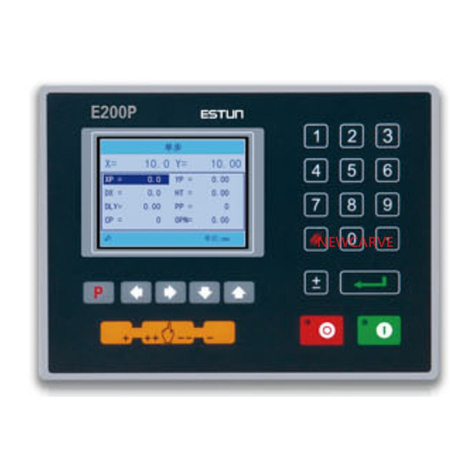
1. The default page is SINGLE; also, you can press Pkey several
times, switching to the SINGLE page.
2. Press Arrow Keys to select the parameter you want to program.
3. Press Numeric Keys to program a desired value.
4. Press Enter Key to complete the setting.
5. Follow the above methods to program the others parameters.
6. After finishing the program, press Startup Key to run the device.
Actual position of the back gauge
Actual position of the slider
Programmed position of the back gauge
Programmed position of the slider
Retract distance of the back gauge
Hold time of punch at the bending point
Delay time in seconds for X-axis retracting
■PP>0, indicates the residual workpieces
■PP=0, indicates the finished workpieces
<INFO> There is one batch of materials, the requirement of bending are as
following: 10 pieces, bend depth is 100.00mm, back gauge position
is 80.00mm, the retract distance is 5.00mm, the delay time for
retracting is 2 seconds, and the holding time is 3 seconds.
<PROCEDURE>
1. Program the parameter XP to 80.
2. Press Enter Key, moving the cursor to the next parameter; and
program the parameter YP to 100.00
3. Press Enter Key, moving the cursor to the next parameter, and
program the parameter DX to 5.00
4. Press Enter Key, moving the cursor to the next parameter, and
program the parameter HT to 3.00
5. Press Enter Key, moving the cursor to the next parameter, and
program the parameter DLY to 2.00
6. Press Enter Key, moving the cursor to the next parameter, and
program the parameter PP to 10
7. Press Enter Key to finish the program.
8. Press Startup Key to run the device.
<INFO> There are 50 pieces of material, which are bent as following:
The first bending: bend depth is 85.00mm, back gauge position is
50.00mm, retract distance is 5.00mm
The second bending: bend depth is 85.00mm, back gauge position
is 100.00mm, retract distance is 5.00mm
The third bending: bend depth is 85.00mm, back gauge position is
300.00mm, retract distance is 5.00mm
Put the above program into Program-No 1.
<PROCEDURE>
1. Press Pkey several times, switching to the PROGRAMS page
2. Select 1and press Enter Key to enter the General Parameters
page; and program the parameter ST to 3
3. Press Enter Key, moving the cursor to the next parameter; and
program the parameter PP to 50
4. Press Enter Key, moving the cursor to the next parameter; and
program parameter DLY to 2.00
5. Press Enter Key, moving the cursor to the next parameter; and
program the parameter HT to 3.00
6. Press Enter Key and <Arrow Right> Key to enter the Step 1
Setting page; and program the parameter XP to 50.00
7. Press Enter Key, moving the cursor to the next parameter; and
program the parameter YP to 85.00
8. Press Enter Key, moving the cursor to the next parameter; and
program the parameter DX to 5.00
9. Press Enter Key, moving the cursor to the next parameter; and
program the parameter RP to 1
10. Press Enter Key and <Arrow Right> Key to enter the next step
parameters setting page; follow the above methods to program the
parameters of Step 2 and Step 3
11. After finishing the program, press Pkey to back the Total
Parameters page or the Step 1 page
12. Press Startup Key to run the device.
1. Press Pkey several times, switching to the CONST page.
2. Press <arrow right> key to enter the ALARM RECORD page.
The page can show the latest 6 alarm info. And, the following table lists
all the alarm info.
Move X-axis forwards in Manual
Movement.
Move X-axis backwards in Manual
Movement.
Move Y-axis forwards in Manual
Movement.
Move Y-axis backwards in Manual
Movement.
Re-teach the position of X-axis.
Rerun, the alarm is cleared
automatically.
Beam is not on upper
dead point
Step on the Foot Up Switch, moving
the slider to the TDC, and the alarm
will be cleared automatically.
Re-teach the position of X-axis.
Re-teach the position of Y-axis.
Check whether the pump signal is
connected, and check whether the
pump switch is on.
Check whether the encoder wiring is
normal.
Reprogram the Drive Mode for
X-axis and Y-axis.
Check whether the back gauge
motor is run normally.
Check whether the slider motor is
run normally.
Check whether the back gauge
motor is run normally.
Check whether the back gauge
motor is run normally.
Check whether the slider motor is
run normally.
Check whether the slider motor is
run normally.
Move X-axis forwards to the setting
range in Manual Movement.
Move Y-axis forwards to the setting
range in Manual Movement.
Back to factory for repairing
The screen don’t display
when power on.
■The terminal of power supply wiring is error.
Follow the nameplate to rewire.
■The source voltage is too low.
■The connector is not connected well.
The back gauge motor
doesn’t run when X-axis
is operated, but the
slider motor runs.
The wires of these two motor are in reverse,
please rewire.
The motor doesn’t run
when operating.
■Check whether the machine is impeded, or
whether the slider is back to TDC
■Check whether the motor wire is connected
well.
The motor can’t mutually
convert from high to low
■Check whether the signal is in effect, or
whether frequency converter is normal.
■Check whether parameter Mute Dis. is
programmed correctly.
The step can’t be
changed in Multi-Step
mode.
Check the START terminal is connected to
+24V when the slider is on TDC.
The counter doesn’t
work in Multi-Step mode.
Check the START terminal is connected to
+24V when the slider is on TDC.
Lose control of the
system
■Check whether the encoder cable is
connected well.
■Check whether the motor direction wiring
(X+, X-, Y+, Y-) is correct.
The actual position of
X-axis or Y-axis is
unchanged or unshown.
Check whether the encoder cable is
connected well or correctly.
When the RED indicator light is on, you can program the parameters.
Only when the page is on SINGLE, Total Parameters page or the Step 1
page, you can press Startup Key to run the device.
Press Stop Key to stop the machine, and the device backs to the previous
When the page displays the alarm info, you should resolve the problem
with some effective measures (see Alarm List). The device will be reset
by the self-diagnosis function.
Manual
Press key, key or key to enter the MANUAL page.
Press Arrow Keys to select the axis you want to adjust, and follow the
below table to operate.
The drive mode of the corresponding axis is motor.
■Press Time (Press Time <
Pulse Time)
■Pulse Time (Press Time >
Pulse Time)
■Press Time (Press Time <
Pulse Time)
■Pulse Time (Press Time >
Pulse Time)
<Note>: When the system is on run status, the operation of manual
movement is just valid for the X-axis.
The drive mode of the corresponding axis is frequency converter.
1. Press Pkey several times, switching to the PROGRAMS page.
2. Press Arrow Keys to select a desired No, or you can press
Numeric Keys to input a desired No, and then press Enter Key to
enter the General Parameters page.
4. Press Arrow Keys to select the parameter you want to program.
5. Press Numeric Keys to program a desired value.
6. Press Enter Key to complete the setting.
7. Follow the above methods to program the others general
parameters.
8. After finishing the program, press <arrow right> key to enter the
Step Setting page.
9. Follow the above methods to program the others step parameters.
10. Press <arrow right> or <arrow left> key to enter the others Step
Setting page, and program the desired parameters.
11. After finishing the program, you should back to the Total Parameters
page or the Step 1 page, and press Startup Key to run the device.
■PP>0, indicates the residual workpieces
■PP=0, indicates the finished workpieces
Delay time in seconds for X-axis retracting
Hold time of punch at the bending point
Programmed position of the back gauge in
the step
Programmed position of the slider in the step
Retract distance of the back gauge
The number of times a step is repeated
before the next step is executed
Diagnosis
<NOTE> The following is only described how to diagnose the encoder, and
for the others diagnosis, just according to the page tips to operate.
1. Press Pkey several times, switching to the CONST page.
2. Press Numeric Keys to input the password 5656, and press Enter
Key to enter the DIAGNOSE page.
3. Select 5. Enc. DIAG. or press Numeric Key 5 directly, and then
press Enter Key to enter the ENC. DIAG. page.
4. Rotate the encoders of X-axis and Y-axis, the page displays the
pulse changing. The corresponding C-pulse will jump between 0
and 1, which indicates the encoder port is normal.
< E21 Installation Manual >
< E21 Operation Manual >
ESTUN AUTOMATION CO., LTD
Add: 155 Jiangjun Road, Jiangning Development Zone,
Nanjing 211106, P.R.China
TEL: 025-52785866
FAX: 025-52785992
WEB: www.estun.com
Email: info@estun.com
