Enomatic eno one User manual

eno one 2/r - user manual
REV.05 1
2-bottle refrigerated
wine dispenser
User manual
Distributed by Neodistributing
5555 Oakbrook Pkwy, Suite 120
Norcross, GA 30093
(800) 705-6940
www.enomatic.us

eno one 2/r - user manual
REV.05 2
TABLE OF CONTENTS
TABLE OF CONTENTS pag.
1. WARNINGS.............................................................................................................4
2. GENERAL INFORMATION.....................................................................................5
3. INTRODUCTION .................................................................................................... 6
4. IDENTIFICATION OF MODEL AND MANUFACTURER .......................................6
5. PACKING AND UNPACKING................................................................................. 7
6. PACKING CONTENTS ...........................................................................................8
7. TRANSPORTATION AND STORAGE ....................................................................9
8. LIFTING AND HANDLING......................................................................................9
9. TECHNICAL CHARACTERISTICS ........................................................................10
10.
COMPONENTS OF THE DISPENSER....................................................................................... 11
11. COMMANDS KEYBOARD AND DISPLAY ..........................................................12
12. POSITIONING....................................................................................................... 13
13. THERMOELECTRIC REFRIGERATION SYSTEM............................................... 14
14. CONNECTING THE GAS .....................................................................................14
15. ELECTRICAL CONNECTION .............................................................................. 16
16. POWERING THE DISPENSER.............................................................................16
17. SECONDARY (STAND-BY) ................................................................................17
18. RUBBER STRAW MEASUREMENT....................................................................18
19. FUNCTIONS MENU ............................................................................................. 18
20. F.1 BOTTLE INSERTION ......................................................................................19
21. REPLACEMENT/REMOVAL OF THE BOTTLE...................................................23
22. F.2 TEMPERATURE SCALE SETTING ...............................................................24
23. TEMPERATURE SETTING ................................................................................... 25
24. DISPENSING ........................................................................................................27
25. F.3 FREE OR PROGRAMMED DOSE SETTING ................................................28
26. F.4 TYPES OF PROGRAMMED DOSES .............................................................30
27. SETTING OF PROGRAMMED DOSES ...............................................................31
28. CO (copy) DOSE PROGRAMMING.....................................................................32
29. nC (not copy) DOSE PROGRAMMING ............................................................... 34
30. CA (copy all) DOSE PROGRAMMING ................................................................35
31. F.5LED INTENSITY SETTING [default value] 10]...............................................36
32. F.6 WASHING AND SANITISING CL.................................................................... 37
33. F7 DISPENSER VERSION....................................................................................38
34. DEFAULT RESET..................................................................................................39
35. WARNINGS...........................................................................................................40
36. WARNING WASHING DISPENSER UNIT cL ......................................................40
37. FAULT ALERT PROBE Pr ....................................................................................41
38. CLEANING THE DISPENSER..............................................................................42
39. CLEANING OF THE EXTERNAL PARTS.............................................................42
40. CLEANING THE COMMAND KEYBOARD AND DISPLAY ............................... 42
41. CLEANING THE DRIP GRILL ............................................................................42
42. CLEANING OF THE BOTTLE COMPARTMENT ................................................. 43
43. CLEANING OF THE RUBBER STRAW ...............................................................43
44. WASHING AND SANITATION OF THE DISPENSER UNIT.................................43
45. SOLUTIONS FOR WASHING AND SANITISATION
OF THE DISPENSER UNIT...................................................................................44
46. DRAINAGE OF THE DUCTS................................................................................44
47. INFORMATION ON MAINTENANCE...................................................................45
48. GENERAL SCHEDULED MAINTENANCE ........................................................45
49. SCHEDULED MAINTENANCE DISPENSER UNIT..............................................45
50. PERIOD OF NON-USE.........................................................................................46

eno one 2/r - user manual
REV.05 3
51. TROUBLESHOOTING ..........................................................................................47
52. INFORMATION ON REPLACEMENTS COMPONENTS..................................... 52
53. DECOMMISSIONING AND DEMOLITION OF THE DISPENSER ......................52
54. DECLARATION OF EC CONFORMITY ............................................................... 53
55. GUARANTEE OF ENOMATIC PRODUCTS.........................................................55

eno one 2/r - user manual
REV.05 4
1. WARNINGS
Before using the Enomatic models, carefully read the instructions contained
in the manual and any other document contained in the packaging
WARNINGS
1. The Dispenser is only intended for professional or similar use in hotels, bars, wine bars,
restaurants and at other commercial facilities.
2. During operation it is essential to pay attention to these safety requirements to prevent risks
of re, electric shock and/or other possible problems.
3. Do not place the Enomatic Dispenser near water spouts and do not immerse the power
cord or other electrical/electronic components in water or other liquids.
4. Do not store explosive substance such as aerosol cans with a ammable propellant in this
appliance.
5. Use and maintenance of the Enomatic Dispenser is permitted by children older than 8, by
persons with reduced physical capacities, with limited sensory or mental abilities, or by
inexperienced persons if supervised or after they have been instructed on safe use of the
appliance, ensuring they have understood the related risks.
6. Keep the appliance and the power cord out of the reach of children under 8 years of age;
7. Children must not play with the appliance.
8. Always unplug the power cord from the machine before cleaning or maintenance;
9. In case it is necessary to move the machine, do not lift or move it with a bottle/bottles
inserted, with the power cord connected or with the gas supply pipe connected.
10.Check the electrical components before using the appliance. In case of damage, contact
your dealer.
11. Do not use electrical appliances inside the bottle compartment unless expressly stated by
the manufacturer.
12.For replacement always request original spare parts and accessories. The use of non-
original spare parts and accessories can cause injury, can damage the equipment and will
void the manufacturer’s warranty.
13.For any repair always contact service centres authorised by the manufacturer or dealer and
request that only original spare parts be used.
14.Do not use the Enomatic models outdoors.
15.Avoid the power cord from dangling or coming into contact with heat sources. Never rest the
machine on its own power cord.
16.Keep the Dispenser away from sources of heat and moisture.
17.Before connecting the Dispenser to the power supply ensure the main switch is set to OFF
(0).
18.Before connecting the Dispenser to the power supply ensure the voltage corresponds to that
indicated on the identication plate.
19.Do not clean the Dispenser with corrosive substances or tools that could damage it. Only
use a soft non-abrasive cloth, dampened with water.
20.Correct cleaning of the Dispenser safeguards its functionality and durability. The solutes
indicated in the user manual may be harmful; avoid contact with the eyes, skin or other parts
of the body.

eno one 2/r - user manual
REV.05 5
2. GENERAL INFORMATION
Purpose of the manual
• The user and maintenance manual, which is an integral part of the ENOMATIC
Dispenser, was designed by the manufacturer to provide the necessary informa-
tion to the user.
• The "ORIGINAL INSTRUCTIONS" were prepared by the manufacturer in
ITALIAN and can be translated into other languages to meet legal and/or
commercial requirements.
• Translations into the language of the country of use, provided by the man-
ufacturer (or by the authorised representative or by the person who intro-
duces the Dispenser into the language area in question), are made from the
"ORIGINAL INSTRUCTIONS" and must bear the words "TRANSLATIONS OF
THE ORIGINAL INSTRUCTIONS".
• Besides adopting good use practices, recipients of the information must read it
and apply it scrupulously.
• A little time dedicated to reading the information can help avoid risks to the
health and to the safety of persons in addition to preventing nancial damage.
• Keep this manual for the entire service life of the Dispenser in a place known and
easily accessible, ensuring it is always available when there is a need to consult
it.
• The manual must always be kept together with the Dispenser upon each transfer
or change of ownership.
• A number of illustrations in this manual may not correspond perfectly to the
conguration of the Dispenser delivered, without prejudice to the integrity and
understanding of the information.
• The manufacturer reserves the right to make changes to the information without
the obligation to communicate this in advance, provided the level of safety is not
compromised.
Directions for reading the manual
• Bold text style indicates parts of text of particular importance.
• Alphanumeric codes in quotation marks e.g. "F.1"indicate the wording that
appears on the display.
• Letters in brackets e.g. (A) indicate the Dispenser components (para. 10 and
11)
• Wording between square brackets e.g. [...], next to the paragraph titles, indi-
cate the default settings of the Dispenser in the sales conguration.
GENERAL INFORMATION

eno one 2/r - user manual
REV.05 6
3. INTRODUCTION
The Enomatic® tasting systems are able to store bottles of wine, controlling the
temperature (refrigerated models only) and preserving, by means of a food-use inert
gas, their content, to then serve it in the desired quantities directly into the glass.
This gas protects the wine from alterations due to oxygenation preserving the char-
acteristics for up to 4 weeks after opening of the bottle.
This
Dispenser
was designed to store and provide the following types of still wine:
dry, sweet, light and sweet. Do not use with sparkling wine.
See para. 49 with the table for the frequency of cleaning the dispensing unit de-
pending on the sugar content of the wine.
Before installing and using your
Enomatic Dispenser, please carefully read the instructions contained in this
manual: these provide important information regarding safety during installa-
tion, use and maintenance.
The manufacturer is not responsible in any way for damage caused by misuse, irra-
tional or irresponsible use of the system or from misinterpretation of the instructions
on safety and installation.
4. IDENTIFICATION OF MODEL
AND MANUFACTURER
The identication plate shown is applied directly onto the
Dispenser
(one on the rear and
one inside the
Dispenser
under the drip
tray).
It contains the identication references
and all the technical data for safe oper-
ation.
1) Manufacturer identication
2) Machine code and model
3) Serial number
4) Type of cooling system
5) Voltage (V) frequency (Hz), absorption (A) or power (W)
6) Fuse characteristics, only if required
7) Operating pneumatic pressure
8) Marking of conformity
9) Danger in case of misuse
10) "read the user manual" warning
11) Disposal indication (Directive 2002/96/CE)
12 Week/Year of production
DO NOT DAMAGE OR REMOVE THE IDENTIFICATION PLATE
1
2
3
4
5
6
7
8 9 10
11
12
INTRODUCTION AND MODEL
eno one 2/r - user manual
REV.05 7
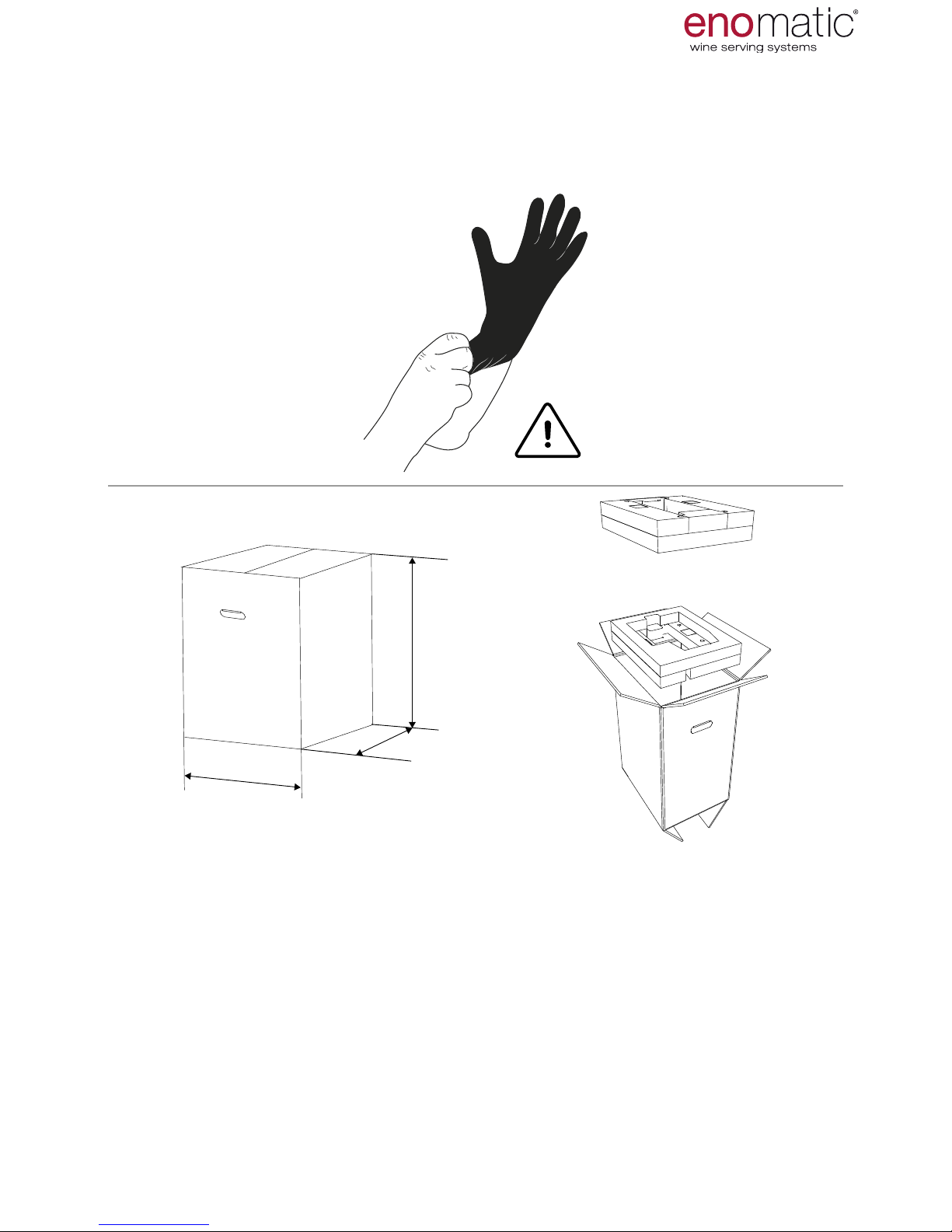
5. PACKING AND UNPACKING
It is advisable to use gloves when removing the Dispenser from the packaging
and for its subsequent handling.
In case of damage or missing parts, do not use the Dispenser but contact your re-
tailer to arrange for the relevant procedure to be adopted.
The Dispenser is sold packed in an appropriate cardboard box with specic an-
ti-shock protectors. Inside the packing the Dispenser is protected by a non-woven
fabric bag.
During unpacking, carefully remove it and check the integrity of the components.
Some of the external and internal surfaces may be appropriately protected with pro-
tective lm which before use should be properly removed.
The package contains all the information necessary to perform movement correctly.
The packaging material, at the Dispenser life end, must be
properly disposed of in compliance with applicable laws.
480 mm
18.90 inch
385 mm
15.16 inch
720 mm
28.35 inch
15 Kg
33,07 lb
PACKING AND TRANSPORTATION
eno one 2/r - user manual
REV.05 8
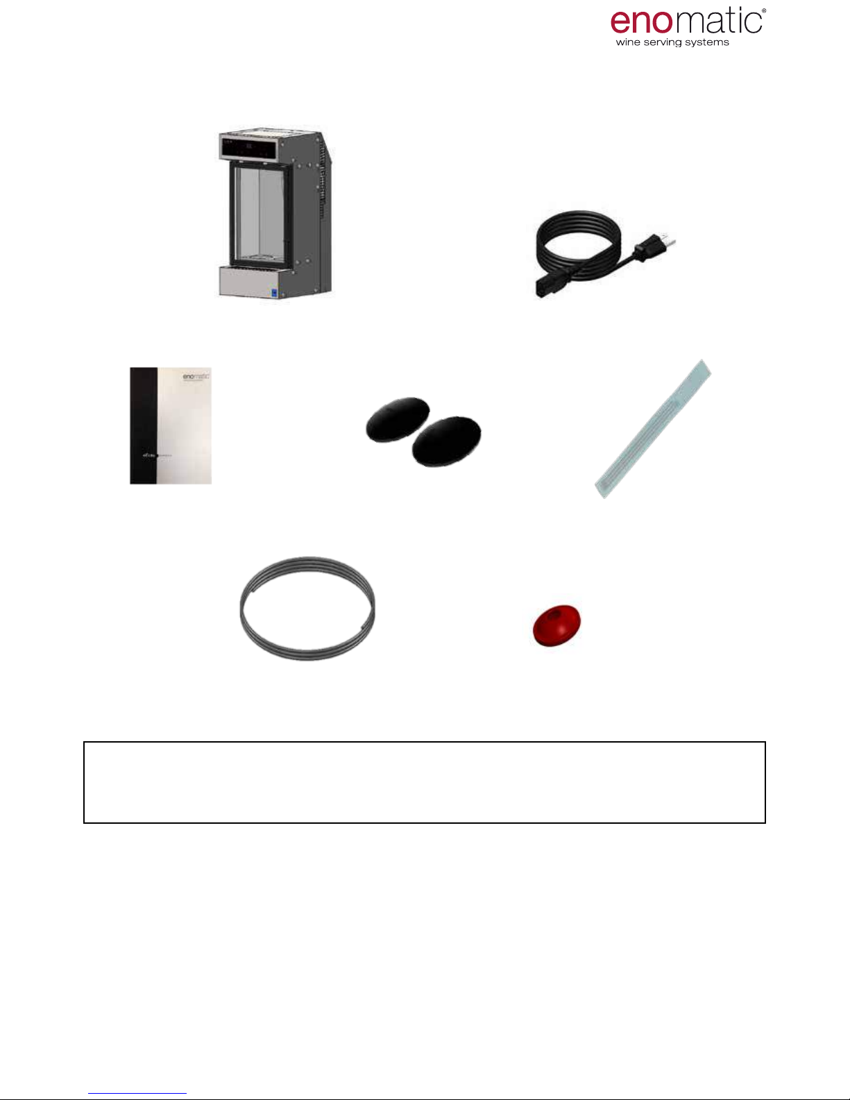
6. PACKING CONTENTS
Ensure the following parts are included in the package:
1 x Warnings 1 x suction straws pack
1 x spare seal for a Cap tap1 x gas connection pipe
A Food LLDPE =Ø4x2.5mm
2 x curved coasters
1 x enoone 2/r dispenser 1 x electrical power cord
PACKING AND TRANSPORTATION
Never leave the packaging parts (such as plastic coverings, etc.)
within the reach of children as they may represent a potential hazard
ACCESSORIES ON REQUEST:
• Side panels (black or white)
• Modularity kit
• Spacer for short bottles
• Conditioning partition for 1 white wine and 1 red wine
• Disposable cylinder and pressure regulator
• Cylinder cover casing
• Graduated cylinder to measure doses
For further information contact your authorised retailer.

eno one 2/r - user manual
REV.05 9
7. TRANSPORTATION AND STORAGE
Transportation, also depending on the
place of destination, can be performed
with different means. The diagram
shows the most commonly used
solutions.
A) Means of transportation
B) Lifting and handling devices
Storage is required if the dispenser is not installed at the time of delivery. If it must
be stored for a long period, it should be placed in a dry protected environment at a
temperature between 0°C and 40°C (32°F and 104°F) and with humidity maximum
of 65% Hr.
8. LIFTING AND HANDLING
The dispenser is designed for free (stand alone) installation and does not require
particular lifting devices given its low weight.
To move the Dispenser lift it up, holding it from underneath.
Do not push the Dispenser, do not drag it or turn it upside down.
If special needs so require it is possible to use the lifting devices
shown in the image above.
PACKING AND TRANSPORTATION
To protect the Dispenser during the
transportation phases, it is deliv-
ered perfectly packaged.
Transportation must be carried out
with the packaging in the vertical
position, as indicated by the sym-
bols directly on it.
The package contains all the infor-
mation necessary to perform move-
ment correctly. During the move-
ment phase, handle the packaging
carefully and avoid overturning as
this could damage the Dispenser.
eno one 2/r - user manual
REV.05 10
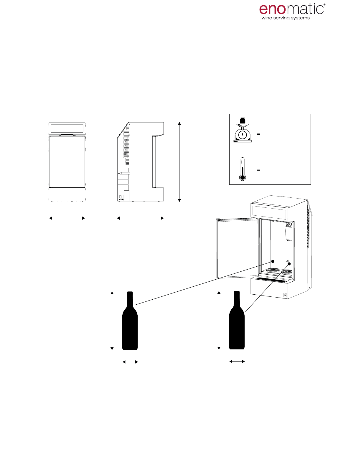
9. TECHNICAL CHARACTERISTICS
Kg
12 Kg
26.46 lb
6 °C ÷ 18 °C
276 mm
10.88 in 13.83 in
351 mm
L= 275 ÷ 330 mm
L= 10.83 ÷ 13 in
598 mm
23.55 in
43 °F ÷ 64 °F
ø < 110 mm
ø < 4.33 in
ø ≤ 90mm
ø ≤ 3.54 in
L= 275 ÷ 330 mm
L= 10.83 ÷ 13 in
CHARACTERISTICS AND COMPONENTS
The Dispenser in the sale conguration allows the insertion of bottles with a maxi-
mum diameter and a height range indicated in the image below.
The right bottle location (when facing the Dispenser), allows the insertion of bottles
with a diameter less than the left side due to the size of the thermoelectric refrigera-
tion system (O).

eno one 2/r - user manual
REV.05 11
A
B
C
D
D
F
G
M
P
D
T3
T4
T2
T1
T
H I L
E
N
O
Q
RS
U
A.
Display and commands keyboard
B. Door
C. Drip grill with tray
D. Rear air vents
E. Cylinder locking strap
F. Identication plate
G. Data connection port
(for technical use)
H. Inert gas connection
I. Power socket
L. Main switch
M. Door handle
N. Plug tap with seal
O. Thermoelectric cooling
system
P. Bottle compartment
Q. Temperature probe
R. LED
S. Dispensing nozzle
T. Bottle raising piston
T1. Gas spring
T2. Spacer
T3. Cylinder
T4. Curved coaster
U. Foot
10.
COMPONENTS OF THE DISPENSER
CHARACTERISTICS AND COMPONENTS
eno one 2/r - user manual
REV.05 12
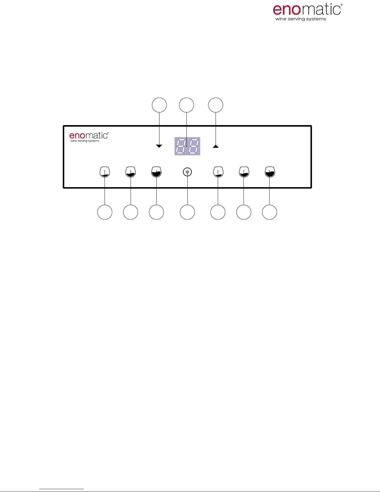
The A-Z references shown on this page and on the previous one,
are mentioned throughout the manual.
V1. Small dose dispensing button (lit)
V2. Medium dose dispensing button (lit)
V3. Large dose dispensing button (lit)
Z. Multifunction button: conrmation, power on/off, output (lit)
X. Increase arrow button
W. Display (lit)
Y. Decrease arrow button
V1 V2 V3 V1 V2 V3Z
XY W
Do not use objects to press the buttons on the keyboard.
use only the ngers of the hand.
11. COMMANDS KEYBOARD AND DISPLAY
CHARACTERISTICS AND COMPONENTS
The keyboard of the dispensers is backlit, as such most of the buttons are
only visible after powering of the dispenser.
eno one 2/r - user manual
REV.05 13
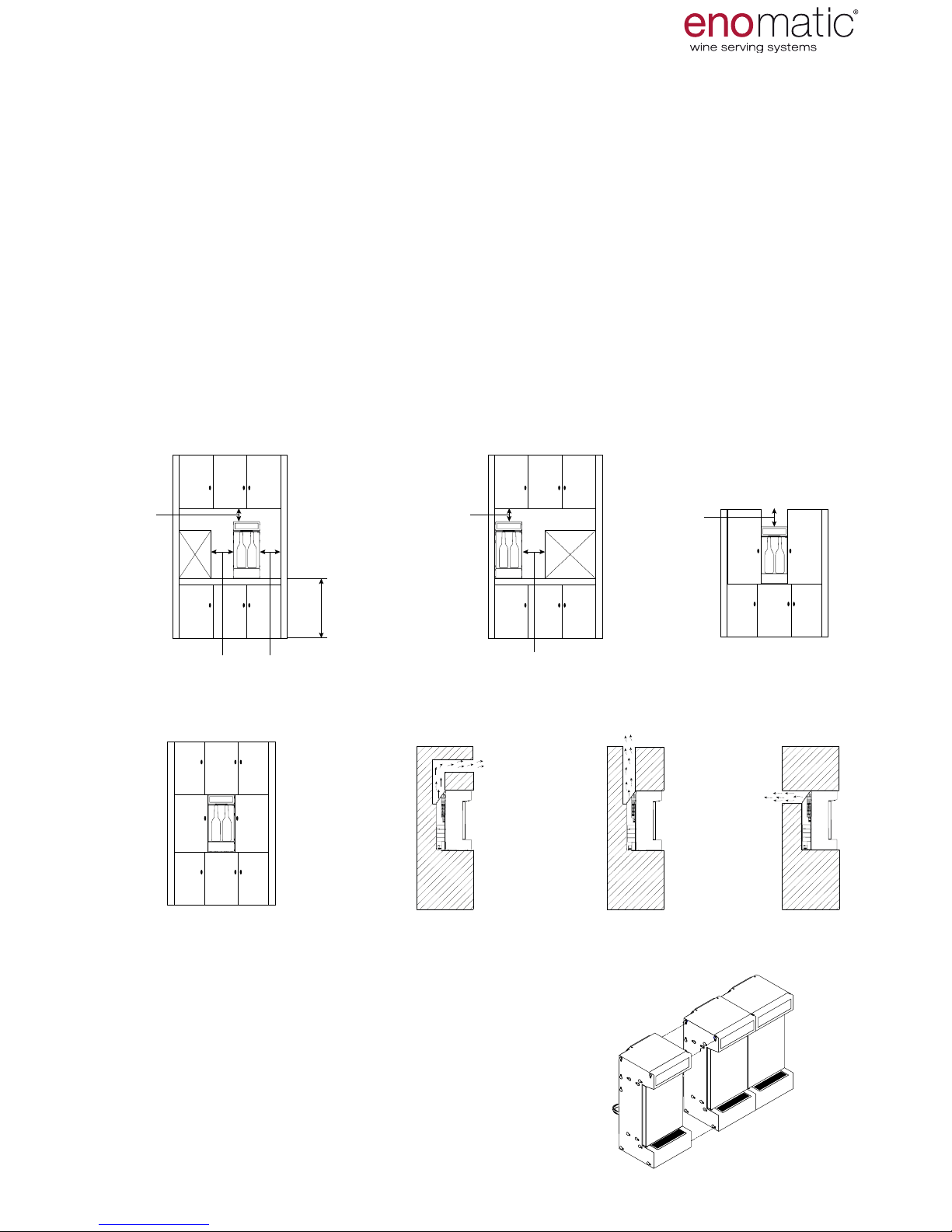
12. POSITIONING
The rst group of images (1) shows the minimum spaces required to
ensure correct ventilation and access to the Dispenser.
In the event of recessing (2), it is necessary to create a structure with an aeration
duct for the circulation of air with a section of at least 100cm
2
(15.5in
2
), directed as in
one of the three examples shown (2.1, 2.2, 2.3).
In this case it is advisable to always consult the retailer before designing the struc-
ture to encase the dispenser.
Place the Dispenser on stable and non tilted surfaces.
To facilitate changing, always position the cylinder in accessible places. In the
case of recessing, it cannot be accommodated in the space rear with strap (E)
of the Dispenser but must be placed in a more accessible place (for example
within the cabinet).
Only place the Dispenser
in indoor dry environments and with a maximum tem-
perature of 26°C (79°F), with humidity no greater than 60% and away from heat
sources.
MODULARITY
Enoone
is a modular dispenser that can
be anked, using a suitable side mounting
system, to another Dispenser of the same
model, that can also be connected to a single
source of gas.
For more information, contact the
retailer.
≥ 20 mm
≥ 0.79 in
≥ 10 mm
≥ 0.39 in
≥ 10 mm
≥ 0.39 in
≥ 20 mm
≥ 0.79 in
≥ 900 - 1000 mm
≥ 35.43 - 39.37 in
≥ 20 mm
≥ 0.79 in
≥ 40 mm
≥ 1.57 in
INSTALLATION
1
2
2.1 2.2 2.3

eno one 2/r - user manual
REV.05 14
250 mm
9.85 inch
100 mm
3.94 inch
352 mm
13.86 inch
A
B
AIR OUTLET
COOLING
AIR INLET
COOLING
14. CONNECTING THE GAS
The operations described below must be carried out by personnel
authorised by the manufacturer or who have been adequately trained.
The use of gloves during the operations to connect the gas and to
replace the cylinder is recommended.
The Dispenser must be connected to a source of food-use inert gas, see table
below.
GAS PERMITTED
Argon (E938) Nitrogen (E941)
The gas is not supplied together with the Dispenser and can be purchased directly
from the Enomatic retailer or from an authorised retailer of food-use gas in the con-
tainers described below:
•
Disposable cylinder
•
Rellable cylinder
In the event of high use of the Dispenser, it is advisable to use a
Nitrogen Generator that is exclusively available from the retailer Enomatic.
Ask the retailer for information on the best choice to suit
your needs.
THE FOLLOWING EXAMPLE ILLUSTRATES THE STEPS TO CONNECT A DIS-
POSABLE CYLINDER WITH ITS PRESSURE REGULATOR TO THE DISPENSER
The gas connection pipe, supplied with the Dispenser (para. 6), is delivered to you
in a length of 0.70 m / 27.56 in, to place the cylinder in the relevant rear space ac-
companied by the strap (
E
). To position the cylinder away from the Dispenser and
to accommodate it, for example, inside the door of any cabinet on which you will be
positioning the Enomatic device, contact the Retailer with regard to the gas con-
nection pipe of the desired length.
INSTALLATION
13. THERMOELECTRIC REFRIGERATION SYSTEM
The dispenser has a thermoelectric refrigeration system (O) controlled by an elec-
tronic board which regulates the temperature of the bottle compartment via a de-
tection probe (Q). The system draws in the air from the drip grill (C) and expels it
through the rear aeration grills (D). Do not place any object on or within the com-
ponents (C) and (D), check constantly that they are not blocked.
Clean the grills constantly referring to the
scheduled maintenance table
(para. 41)
and perform the recommended
daily and
annual cleaning (para. 48.
Do not leave the cooling system acti-
vated with the door open. During oper-
ations on Dispenser that involve
continuous or protracted openings of
the
door, such as emptying of the ducts or
replacement of the bottle, it is recom-
mended to switch off the refrigeration
setting the temperature to "OFF" = off
(para. 23).
IMPORTANT
For correct operation and duration over time, carefully follow the information
indicated above.

eno one 2/r - user manual
REV.05 15
1
2
3
4
= 4 X 2,5 mm
10
12
1
2
3
4
= 4 X 2,5 mm
10
12
1. Unscrew with your ngers the safety nut
from the tting of inert gas connection (
H
).
2. Remove the safety nut from the tting.
3. Take one end of the gas connection pipe,
insert it within the safety nut and connect
the pipe by pushing it with force as far as
possible on the inert gas connection tting
(H), being careful not to tilt the Dispenser.
4. Tighten the nut to secure the pipe by
squeezing it as much as possible with your
ngers.
5. Take the pressure regulator to the dispos-
able cylinder (gure to the side)
6. Unscrew with your ngers the safety nut
from the cylinder pressure regulator con-
nection tting
.
7. Remove the safety nut.
8. Insert within the safety nut the other end
of the pipe and connect it with force to the
tting, pushing it to the end.
9. Tighten the nut to lock the pipe, squeezing
it as much as possible with your ngers.
10. Place the bottle on the working sur-
face, remove the plastic protective cap
and screw it quickly down to the bottom
of the pressure regulator (rotate the cyl-
inder while holding the regulator still
to prevent the gas connection pipe
from twisting). A small leak during the
screwing stage is in any case envisaged
therefore at this phase accelerate tight-
ening.
11. Open the pressure regulator valve to
minimum 4 Bar and maximum 6 Bar.
12. Place the bottle in the appropriate rear
space of the Dispenser, supporting the
base on the surface and fasten it with the
specic locking strap (E) or place it close
to the Dispenser.
6
8 9
7
INSTALLATION
1
2
3
4
= 4 X 2,5 mm
Should it be necessary to disconnect the Dispenser from the gas supply, never
directly extract the pipe from the machine without rst having closed the valve
on the pressure regulator. Close the regulator valve. Only unscrew the cylinder
from the pressure reducer if it is tted with a safety needle valve.
DISPOSABLE PERFORATION CYLINDERS MUST NEVER BE
REMOVED BEFORE THEY ARE COMPLETELY EMPTY
Carefully read all of the safety guidelines of the cylinder (container under pres-
sure) before manipulating it.

eno one 2/r - user manual
REV.05 16
15. ELECTRICAL CONNECTION
Before connecting the Dispenser to the electrical mains, always check the compat-
ibility of the voltage comparing it with the data indicated on the identication plate
(F).
For safely reasons, it is absolutely essential that the Dispenser is
connected to an electrical network equipped with an effective earthing sys-
tem, performed in accordance with the legal technical regulations.
Ensure the Dispenser does not experience power surges due to interference
from other equipment connected to the same electrical network that could
alter the normal functioning of its electronics.
Before connecting the plug to the electrical mains, check that the main switch
(L) is in the "0" = OFF position.
Insert the power supply cable into the socket (I)) of the Dispenser.
Insert the plug of the supplied cable into the wall socket.
INSTALLATION
From now on, it is possible to continue without
using gloves.
Place the main switch
(L) in position
"I" = ON
The Dispenser starts and performs
a functional check, indicated by
the simultaneous ashing of all the
buttons (V) and of the display (W).
The LED (R) comes on.
After a few seconds, the Dispens-
er passes to the operating status
illuminating only the active
Dispensing (V) buttons with acti-
vation of the thermoelectric mod-
ule function for refrigeration of the
bottle compartment (P).
1 2
1 2
> 10”
3”
3’’
< 5”
16. POWERING THE DISPENSER
After having installed the Dispenser the next step is switch on
and its use.

eno one 2/r - user manual
REV.05 17
17. SECONDARY (STAND-BY)
ON/OFF
The Dispenser can also be switched on and off with the conrmation button (Z),
when the main switch (L), present on the rear panel, is not easily accessible.
In stand-by mode the Dispenser is actually switched off (dispensing is not per-
mitted and refrigeration is disabled) even if powered by the electric mains.
From the operating state press the
multifunction button (Z) until 8.8.” ap-
pears on the display after the display
of "F1"
When the button is released, the Dis-
penser
switches off leaving only the
lit conrmation button (Z) on.
Rest condition (stand-by)
To switch on the Dispenser from the
stand-by condition, simply press the
conrmation button (Z) until power-
ing of the display.
USE AND OPERATION
eno one 2/r - user manual
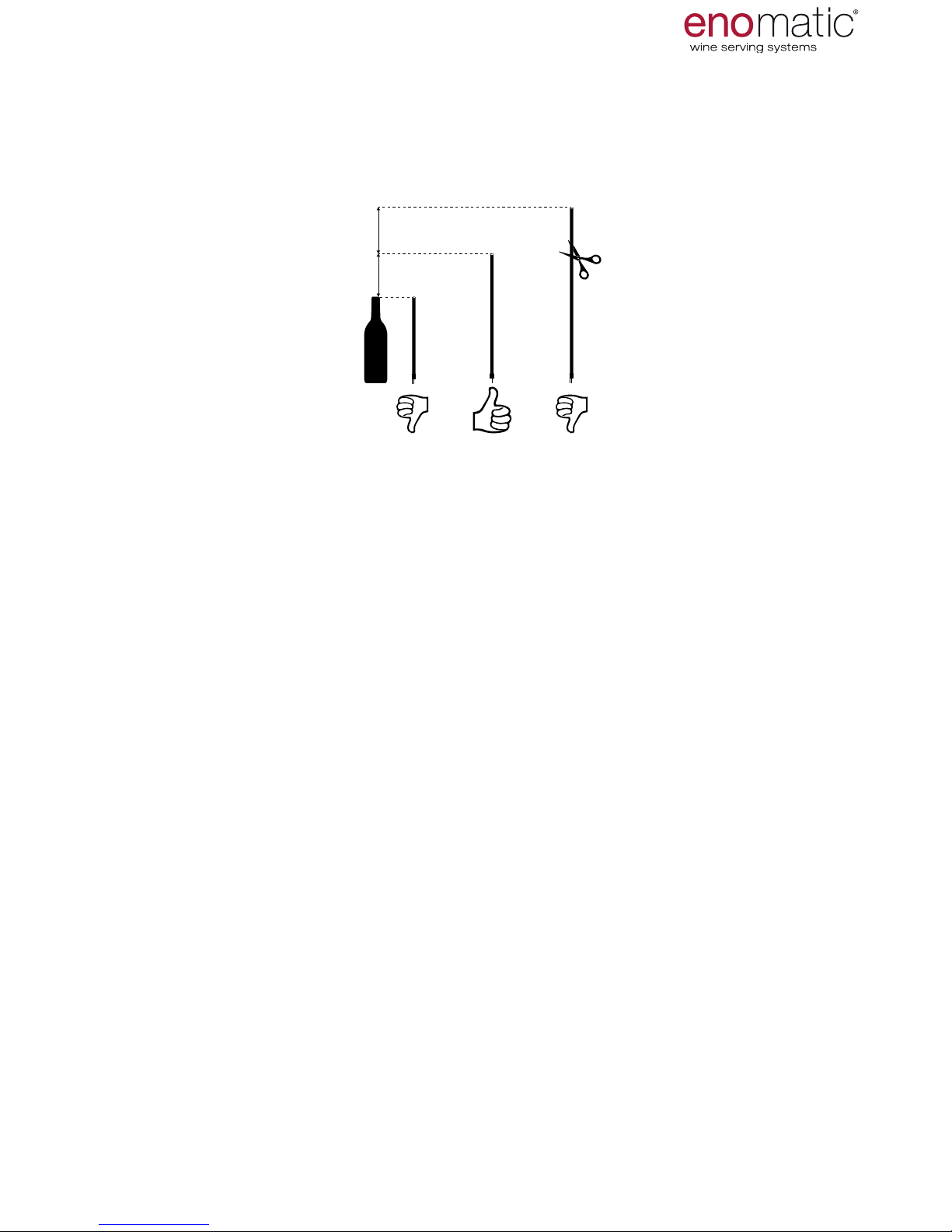
REV.05 18
Before insertion into the bottle ensure the correct length of the straw. Place the
straw next to the bottle to be inserted. The recommended length of the straw must
be at least 2 cm (0.79 in) higher than the length of the bottle and
never more than 5 cm (1.97 in).
If the straw is longer, cut it using a pair of scissors.
A straw that is too long could bend inside the bottle
limiting the passage of the liquid possibly resulting in its complete obstruction.
If the length is less than that suggested, replace the straw with one that is ade-
quate. An overly short straw will not allow dispensing of all the liquid
inside the bottle.
Always replace straws that are deteriorated from use. (e.g. torn, deformed).
Further straws can be obtained from the retailer Enomatic.
18. RUBBER STRAW MEASUREMENT
no.3 rubber straws are supplied, necessary to remove the wine from the inside of
the bottle and to convey it to the plug tap (N) of the
Dispenser unit. The end of the straw where the lter that restricts the passage of
wine sediments is located must be inserted into the bottle while the other end must
be connected to the plug tap.
2÷5 cm
0.79÷1.97 in
>5 cm
>1.97 in
19. FUNCTIONS MENU
The Dispenser has a menu with features that are useful to set the main parameters
and in order to interact with it. To access the Functions menu press the multifunc-
tion button(Z) for 3 seconds and release it as soon as the letters "F1" are displayed.
Scroll with the arrow buttons (X,Y) to select the desired setting
and then press the multifunction button (Z) once.
to access the specic function. The operation described above must be carried out
within a few seconds otherwise the Dispenser will automatically trigger the time-out
mode, returning to the previous menu without having stored any function/parameter.
Below is shown the correspondence of the functions to the related acronyms dis-
played on the lit display (W):
F.1
BOTTLE INSERTION
F.2
TEMPERATURE SCALE SETTING
F.3
DOSE MODE SETTING
F.4
DOSE PROGRAMMING
F.5
LED INTENSITY SETTING
F.6
WASHING AND SANITISING
F.7
DISPENSER VERSION
USE AND OPERATION

eno one 2/r - user manual
REV.05 19
For the initial and correct insertion of the bottles and for subsequent replacements
of the bottles, follow the steps described below. In particular the centring and stabi-
lisation activities must be performed well to quickly replace bottles, as described in
the bottle replacement/extraction paragraph (para. 21)
It is recommended that the temperature of the bottles to be inserted only dif-
fer by a maximum of 4°C (7.2°F) from the value set for the bottle compartment
(para. 23).
3’’
3’’
click
3’’
3’’
click
20. F.1 BOTTLE INSERTION
3’’
3’’
click
T3
T4
T2
From the operating state
Press
the multifunction button (Z) for 3
seconds and release it as soon as
the letters "F1" are displayed.
Press the multifunction button (Z) to
access the function chosen.
The Dispenser is on hold for loading
of the bottles after which the medium
dose button (V2) of each dispensing
unit will ash. During this function
refrigeration is switched off to limit
energy consumption.
The Dispenser remains in this po-
sition for 10 minutes, after which it
automatically returns to the operating
state.
Open the door (B) and insert the suc-
tion pipe on the relevant
nozzle of the plug tap (N),
pushing rmly until it is fully inserted.
Repeat the same operation for the
other position.
Check for the presence of a
spacer (T2) and of a cylinder (T3).
Place on the cylinder
a curved coaster (T4) supplied
with the Dispenser (para.10 ). Repeat
the same operation for the other po-
sition.
When inserting bottles with a at
bottom remove the curved coaster.
USE AND OPERATION

eno one 2/r - user manual
REV.05 20
Make sure that the bottle raising pis-
ton (T) is in lock position (1).
Where the bottle raising piston (T)
is in an elevated position (2) push it
down with your hand as far as the
lock position (1).
(2) (1)
Insert the straw into the bottle
being careful not to bend it and rest
the bottle on the raising piston (T).
Take the base of the neck of the
bottle with both hands and push it
downwards, exerting a pressure in
order to release the bottle raising
piston (T) and to enable its ascent.
Accompany the bottle until its mouth
is resting on the seal of the plug tap
(N).
USE AND OPERATION
Table of contents
Other Enomatic Beverage Dispenser manuals

Popular Beverage Dispenser manuals by other brands

Frosty Factory
Frosty Factory 289A Service manual

FBD
FBD 77 Series Installation and operation manual

Narvon
Narvon 378D2B26 user manual

Grindmaster
Grindmaster Standard 3311 parts list

Cornelius
Cornelius remcor DB275--BCP Operator's manual

Servend
Servend Ice & Beverage Dispensing Units Technician's handbook

MICROMATIC
MICROMATIC JOETAP JT-CTMG Installation, use and maintenance guide

Servend
Servend STH14 Technician's handbook

Nostalgia Electrics
Nostalgia Electrics RETRORED FBS400 Instructions and recipes

Bunn
Bunn SRU/U3 Installation & operating guide

Cornelius
Cornelius Ice Cooled Dispensers Operator's manual

TAPRITE
TAPRITE Rattler II Instructional manual


