7
side of the copper tubing since the refrigerant gas is heavier
than air. Where copper tubing is protected by an insulating
jacket, check for leaks at both ends of each jacket section.
.
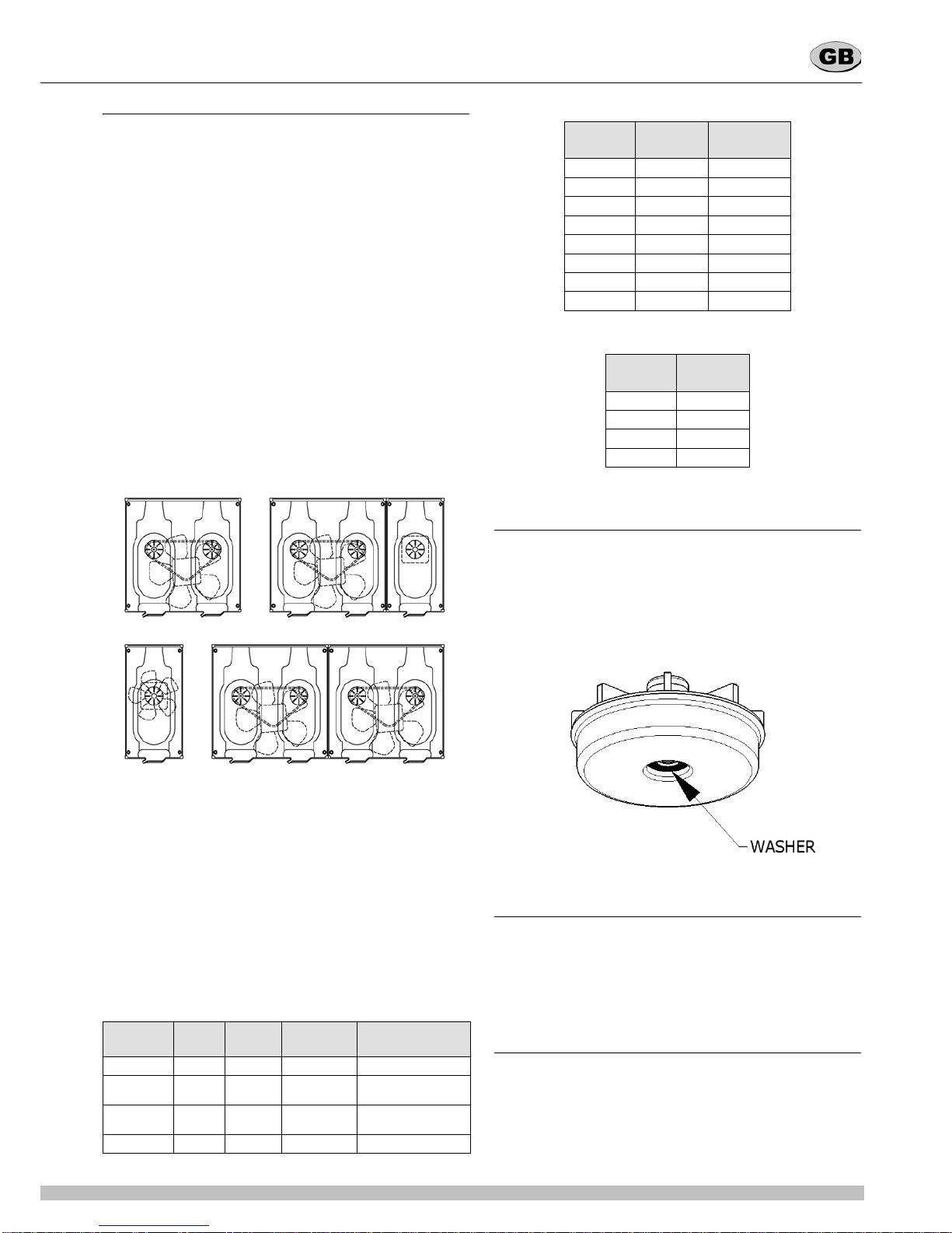
figure 7
Referring to the diagram (see figure 7), perform the following
steps:
1Start inspection at the high pressure line of the compressor.
Check around the soldered connection.
2Follow the copper tubing to the condenser and check
around the soldered connections at the top and bottom of the
condenser.
3Check also along the copper curves on both sides of
condenser.
4Follow the copper tubing to the evaporators, checking
around the soldered connections of dryer.
5Remove mixer motors and check the inlet (capillary) and
outlet (suction) tubing.
6Check the copper tubing all the way back to the
compressor.
7Check around the low side connections of the compressor
suction and process tubes.
If a leak has been detected, seal it and make a new refrigerant
charge as per instructions in the following paragraphs.
6. 2 DISCHARGING
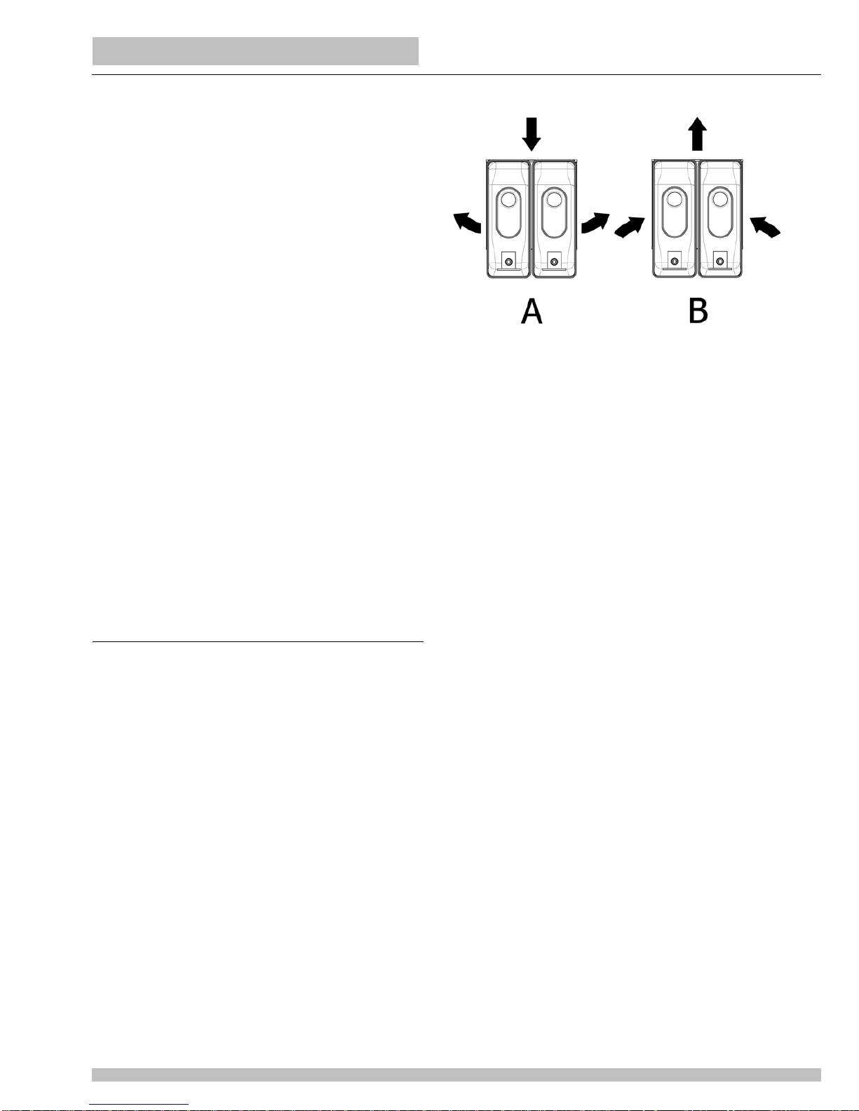
1Remove the dispenser panels.
2If not present install a charging valve on the compressor
process tube.
3Remove the screw cap from the compressor process tube.
4Connect the process tube to the LOW part of the gauge set.
5Connect the VAC port of the gauge set to an adequate
approved gas recovery system.
6Open the LOW and VAC valves and recover the refrigerant.
7Once the recovery operation is completed, close the LOW
and VAC valves and disconnect the recovery system.(see
figure 8)
figure 8
6. 3 EVACUATING
Always install a brand new liquid line filter dryer before
evacuating.
1Connect the REF port of the gauge set to the charging unit.
2Connect the VAC port of the gauge set to the vacuum pump
and open the VAC valve.
3Open the line valve of the charging unit and, for a while,
also the REF valve, so as to purge air from the REF hose.
4Open the LOW valve of the gauge set and turn on the
vacuum pump for a minimum of half an hour.
5While the pump is running, close the VAC valve once a
vacuum has been established.
6Turn off the vacuum pump.
6. 4 CHARGING
The gauge set is usually with four ports and four valves (see
figure 8). This is the easiest option to be found in the market
since it allows the charging through both low and high side of the
system. Our refrigeration systems are manufactured so as to be
chargeable through the compressor process tube only (low
side): thus, the HI port is never mentioned nor used in the
following procedure and therefore the HI valve must be kept
closed.
1Determine how many ounces/grams should be filled by the
charging unit. This information can be found on the dispenser
data plate.
2Remove bowls and mixers from the dispenser.
3Plug in the dispenser and turn on the power switch.
4Open the line valve of the charging unit.
5Open the REF valve very slowly so as to allow the
refrigerant to be pulled into the system as a gas.
6When the amount of refrigerant listed on the data plate has
been used, the system is charged. Close the REF valve and
the charging unit line valve and allow the compressor to run few
minutes.
7Ensure that all evaporator plates are covered with frost.
8Close the LOW valve, disconnect the LOW hose from the
compressor process tube and tighten the screw cap.
The following table reports the suction and discharge pressures
of the machines with the different refrigerants.
They must be verified under the following conditions:
Ambient temperature: 32 °C
Product temperature in the bowls: 5 °C
Evaporation temperature approx -5 °C
Condensation temperature approx 50°C.
IMPORTANT
To check for a leak in the low side of the system, it is
advisable to have the evaporators at least at ambient
temperature.
ATTENTION
The refrigerant gas could be highly acid and toxic.