Sureguard Pro-Tech 5 User manual


2

3
Electric Fencing Re-envisioned
Sureguard’s 5th Generation Solar Electric Fence Energizer.
Features
Latest Solar Panel & Battery Technologies
•Not just for the Australian sun. Pro-Tech 5 has outstanding fence performance even
in prolonged cloudy conditions.
Keylock Security Mounting
•Your Pro-Tech 5 has a unique key-locking mechanism that safeguards your
investment against theft.
Massive 190 Joule Lightning Surge Protection
•In-built surge protection will help to safeguard your Solar Energiser.
Pure Copper High-Voltage Transformer
•Sureguard’s pure copper design eliminating losses typical of other designs.
Use with Various Fencing Materials
•Use Steel Fencing Wire, Polywire, Polytape, Polybraid or Polyrope.
How does an electric fence work?
An electric fence is designed either to contain animals within a designated area or to deter
unwanted animals from entering. It operates by delivering high-voltage electrical pulses from the
Energiser's "Live" Terminal to the fence wire, electrifying it. This wire is carefully insulated from its
supporting posts. The "Earth" Terminal of the Energiser connects to an Earth Electrode that is
embedded deep in the ground. This configuration completes an electrical circuit with any animal
that comes into contact with the fence, as illustrated on page 4.
These electrical pulses are brief, lasting only a fraction of a second, and occur at a rate of 30-50
times per minute. When an animal touches the electrified fence wire, its body completes the
electrical circuit. This results in a brief yet uncomfortable muscle contraction prompting it to move
away from the fence. Due to the distinct sensation, animals quickly learn to avoid the fence.
For optimal results, select a fence design tailored to your circumstances. This can be a single wire,
multi-wire, mesh, or a combination of these designs.
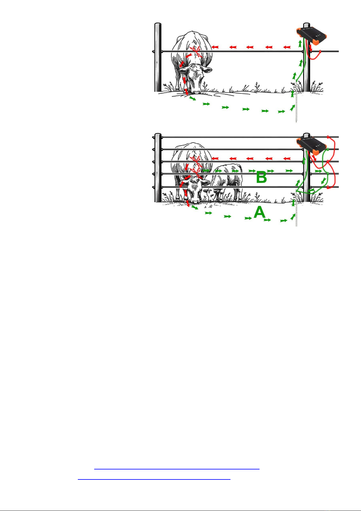
Single Wire Fence
This is a straightforward fence design consisting of a single electrified wire (page 4). When an
animal contacts this "Live" Wire, the electrical pulse travels through the animal's body, down its
legs, and into the ground. From there, the pulse moves through the moisture in the sub-soil layer
(usually about 1m or 3ft deep) and returns to the Energiser's Earth Terminal via the "Earth
Electrode". In this setup, the animal's body acts as a conduit between the Live and Earth Terminals
4
of the Energiser. While simple, a
drawback is that the strength of the
electrical pulse weakens as it travels
further through the soil to the Earth
Electrode.
Multi-Wire Fence
As an alternative, there's the multi-wire
fence which includes one or more Earth
Wires. These Earth Wires can be
connected through metal support
posts, ensuring consistent grounding.
They also allow adding more Earth
Electrodes along the fence, boosting
its effectiveness.
This type of fence may consist of 3, 5,
7, or even more wires, with alternate
connections to the Live or Earth
Terminals. It's ideal for fencing that
spans more than 1km (or 3000ft) or in
regions with specific conditions like
low soil moisture, sandy terrains, shallow topsoil, or droughts. It's also a preferred choice for
managing hard-to-contain animals, pest control, or enclosures housing animals of various sizes.
The multi-wire fence offers two return paths for the electrical pulse to the Energiser:
A/ Via the Live Wire, through the sub-soil moisture, back to the Energiser. Its efficacy is contingent
on the soil's moisture content and the distance from the animal to the nearest Earth Electrode.
B/ Directly through the animal, between its contact points with the Live and Earth Wires. This
design offers the highest deterrence due to its minimal electrical resistance, ensuring a strong
electrical pulse.
Mesh Fence
For controlling pests like foxes and wild dogs, a grounded high-tensile mesh fence topped with one
or two Live Wires provides an excellent barrier. The mesh prevents these animals from squeezing
through or under, while the Live Wires deter them from climbing.
Earth Electrode
You must install a proper Earth Electrode. Use ONLY GALVANISED steel, pipe or fence posts (star
pickets). DO NOT use bitumen-covered posts or rusty metal because these will reduce the intensity
of the pulse to the animal. You want the Earth Electrode to have as much conductive surface area
in contact with sub-soil moisture as possible. Typically, you should drive the Earth Electrode 1.5m
into the ground. Don’t overlook this point! Then at distances of about every 500~1000m along the
multi-wire fence, add more Earth Electrodes and connect these to the Earth Wires of the fence.
For more design information & worthwhile tips, visit our website at:
Electric Fence Design: www.sureguard.com.au/page/electric-fence-design
Tips and videos: www.sureguard.com.au/page/video-pro-tech-5
5
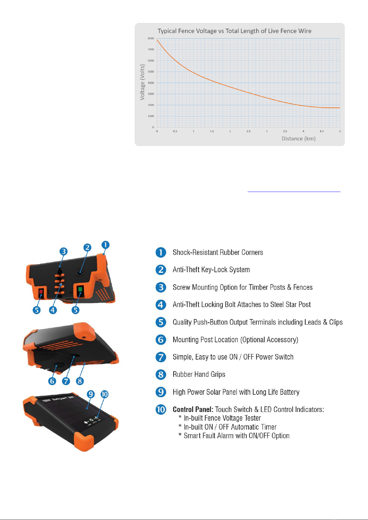
Specifications
•Maximum Distance Rating:
5km or 3 miles.
•Weight: 0.93kg (33oz)
•Dimensions: 195mm Wide.
100mm High. 220mm
Deep. (4.95" x 3.95" x
8.65").
•Output Impedance:
Excellent (Low).
•Pulse Energy: 0.2 Joules
(stored energy).
•Pulse Voltage: 8000 Volts (typical).
•Surge Protection: Varistor technology 190 Joules.
•Battery Life: About 5 to 8 years under typical operating conditions. Wiki: Battery Technology LiFePO4.
Solar Powered Fence Energiser

6
Mounting Location
The Energiser is solar-powered and requires a
suitable location for reliable operation.
1/ It must have an uninterrupted view of the sky
from east to west.
2/ No shadows over the Solar Panel between at least
10am to 2pm.
3/ The Energiser must also point towards the
equator; in Australia, that means northward.
TIP: Stand behind the Energiser with the Terminals in
view. Confirm you are looking northwards. (NOTE: In
the northern hemisphere, the equator is southward.)
The Solar Panel will charge quickly in full direct
sunlight. In cloudy conditions, the sun’s intensity is
lower, and the charge time is longer, but the Solar
Panel still collects power from the full view of the
overcast sky.
IMPORTANT: The Solar Panel only charges while the
Energiser is switched ON.
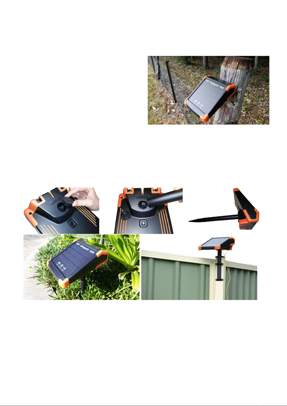
Mounting Options
The Energiser has several mounting options –see Key #3, #4 & #6 illustrated on page 5.
Steel Post Anti-Theft Mounting
Refer to Key #4. We recommend you mount the Energiser on top of a steel post or “star
picket”used for electric fencing. The Energiser’s internal mounting bolt locks the Energiser
to the post and is easily attached or removed using the supplied Key.
Locking Procedure:
1/ Remove the rubber sealing plug and insert the supplied Key.
2/ Align the mounting bolt (see Key #4 on page 5) with the top hole in the post.
3/ Rotate the Key anticlockwise to retract the mounting bolt.
7
4/ Push the Energiser onto the post. Jiggle until you hear the bolt click into the hole.
5/ Rotate the Key clockwise to lock.
6/ Make sure the Energiser cannot come off. Then remove and store the Key
7/ Put the rubber sealing plug back into the keyhole as an insect & weather seal.
IMPORTANT: The top of the steel post must
not be mangled or damaged as it might
damage the mounting point.
Screw Mounting
Refer to Key #3 on page 5. Insert a single M4
screw (4mm thread with a head no more
than 9mm) into timber, steel or plastic
fencing or posts. Hang the Energiser using the
screw mounting (illustrated on the right).
Plastic Mounting Post
Refer to Key #6 on page 5. A plastic Mounting Post is available as an optional accessory.
Assemble its three parts. Remove the protective rubber bung and push the post into the
base of the Energiser. Push the other end of the post into the soil or screw it onto an
existing fence using two 25mm Saddle Clamps (clamps and post not included).

8
Connecting Energiser to Fence
Included with your Energiser are quality Silicone High-voltage Cables with rust-resistant
alligator clips and 15mm pre-cut insulation on the end. For each Cable, remove the pre-cut
15mm of insulation with a twisting motion, so the copper wires become twisted together.
Then fold the copper wires back over themselves by 5mm. (As illustrated with the red wire).
With the Energiser switched OFF, push the Red Terminal button to open the metal jaw and
insert the copper wire, so it is touching the Terminal’s metal contacts. Release the button.
Ensure its securely held. Now, repeat the same process for the Green Cable.
Attach the Red Alligator Clip to the
Live fence wire and Green Alligator
Clip to the Earth Electrode and/or
Earth Wires. Switch ON to energise the
fence.
For steel fencing wire and Polywire,
simply attach the Red Alligator Clip as
shown below. You cannot do this for
Polytape. The Alligator Clip won’t
correctly energise all the wires, and you may create sparks. The correct method is to:
1/ cut the Polytape,
2/ tie the two ends together in a secure knot,
3/ pull ALL the wires free from each end,
4/ twist all the wires together,
5/ connect the Red Alligator Clip to these twisted wires. You can also use this method to
reliably join two pieces of Polytape or Polywire together anywhere along the fence.

9
Switch Energiser ON
Use the ON/OFF Switch on the underside of the Energiser to toggle ON or OFF.
(“I” is ON, “0” is OFF)
The energiser is supplied ready-to-go. When you
switch the Energiser ON, you will see two LED
lights on the Solar Panel. The POWER LED relates
to the charge in the battery. The FENCE LED
relates to the measured fence voltage. Each LED
can light Green, Red or Blue. Refer to the table
below for what the colours mean. Two green
lights mean you are good to go!
NOTE: Critical issues will cause the LED to flash
RED & Alarm Buzzer to sound. Read Advanced
User Features if you want to customise the
Buzzer.
What the LED Colours Mean:
POWER
LED
GREEN
Normal operation. The internal battery has plenty of power.
GREEN
FLASHING
If both the Power & Fence LED are flashing green, then contact Sureguard
for assistance.
RED
The internal battery is low. Check Solar Panel is clean and set up correctly.
RED FLASHING
Critically low battery. Rectify immediately! (Troubleshooting page 11).
BLUE
Displayed while using the advanced optional Settings Switch (page 10).
NOT LIT
The Energiser is switched OFF or the battery is too depleted. Switch ON to
commence charging. The Power LED flashes RED momentarily every few
seconds while charging. The Energiser will resume operating automatically.
FENCE
LED
GREEN
The fence voltage is good.
RED
The fence voltage is low. Check the condition of the fence.
RED FLASHING
The fence voltage is very low. Rectify immediately! The Energiser will be
pulsing more slowly in this condition. (Troubleshooting page 11).
BLUE
You have selected the ON/OFF Timer. The fence is currently inactive. (Refer
to page 10, Function #3 and #4).
BLUE FLASHING
It displays when you switch the Energiser ON. It is analysing the fence
voltage, but the readout is not available yet.
NOT LIT
See above.
10
Advanced User Features
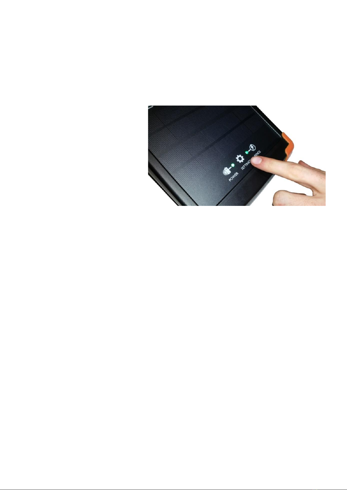
The cog icon on the Solar Panel is a Touch Switch that works from moisture in your finger.
When you switch the Energiser ON, the Touch Switch is active for the first 45 seconds.
During this time, you can customise the operation of the Energiser. Your settings will be
stored even if the power is switched OFF.
NOTE: If the cog area is wet, dry it before using the Touch Switch.
How to Enter the Advanced Features Mode
1. Switch the Energiser OFF. Wait
10 seconds. Switch ON.
2. Wait until the FENCE LED stops
flashing BLUE.
3. Touch the cog icon for about 1-
second until both LED lights glow
BLUE.
TIP: Touch lightly, don’t press
hard. If your finger is small, use
your thumb.
4. As soon as both LEDs glow BLUE, remove your finger off the cog.
5. Wait until both BLUE LEDs go OFF.
6. Momentarily tap the cog icon the number of times required to match the function you
want to enter (as per the list below). TIP: You’ll find the Touch Switch responds better
when you press and release, moving your finger at least 2cm away from the cog.
❖Touch once (Function #1):
Reset all functions to factory default and performs the following hardware tests:
1/ LED’s light in sequence RED-GREEN-BLUE.
2/ Alarm Buzzer sounds.
3/ Solar panel, in sunlight, is linked to the POWER LED. It will flicker BLUE to verify power
is going into the battery. NOTE: If the battery is fully charged, the POWER LED will not
flicker BLUE. So, it is best to test first thing in the morning after running all night so the
battery will accept charge.
4/ Energiser reboots automatically after 20 seconds.
❖Touch twice (Function #2):
Timer is switched OFF. Energiser will operate 24-hours a day. (Factory default setting).
❖Touch 3 times (Function #3):
Timer is switched into Night Mode. The Energiser will power the fence at night, starting
about 15-minutes after sunset. During the day, the Energiser is in standby mode. The
FENCE LED will glow BLUE. The Solar Panel will continue to charge the battery. NOTE:
The Alarm Buzzer may sound if a fault occurs at night. This behaviour can be customised
by Function #5. To locate the fault, do a factory reset (Function #1), then check the
points under “Rectifying Fence Faults.

11
❖Touch 4 times (Function #4):
Timer is switched onto Day Mode & will only operate during the day, starting about 15
minutes after sunrise. At night the Energiser is in standby mode, and the FENCE LED
glows BLUE. NOTE: The Alarm Buzzer may be customised by Function #5, or #6.
❖Touch 5 times:
Switch the Alarm Buzzer OFF. It will not sound if a status error occurs.
Touch 6 times:
Switch the Alarm Buzzer ON and make it active only during daylight hours. (Factory
default setting).
❖Touch 7 times:
Switch the Alarm Buzzer ON and active day or night (when operating in 24-hour mode).
❖Touch 8 times:
Report the current fence voltage in kilovolts (0.5 to 9.9kV). The fence voltage is helpful
for fence diagnostics. Count the number of flashes of POWER LED; this is the first digit.
Count the number of flashes of the FENCE LED; this is the second digit.
The normal voltage range is 2kV to over 8kV
NOTE: If necessary, select Function #2 to put the Energiser into 24-hour Mode.
❖Touch 9 times:
Like Function #8, this reports the lowest fence voltage since midnight. (Useful for
diagnostics).
❖Touch 10 times:
Like Function #8, this reports the highest fence voltage since midnight.
❖More than 10:
Does nothing. Beeps an error.
Rectifying Power Faults
POWER LED Continuously RED:
The internal battery needs more charge. The Energiser will automatically lower its power
consumption to continue operation. It will pulsate less frequently. Check the following:
1. Clean the Solar Panel with water; remove bird droppings and dust.
2. Confirm your solar setup is as described in “Mounting Location”.
3. Confirm the panel is facing toward the equator (not east or west), not experiencing
shadowing and can see as much of the sky in all directions as possible.
4. A temporary low power condition may occur during dark cloudy conditions.
POWER LED Flashing RED:
1. In addition to the above points, select Function #1 to test the hardware and Solar
Panel.
2. If your solar location is not ideal, consider setting the Energiser to run in either Night-
Mode or Day-Mode (if acceptable).
POWER LED is OFF:
The Energiser has entered a low-power Sleep Mode to avoid depleting the battery. This
condition might happen if you forgot to switch the Energiser OFF when putting it into

12
storage. To rectify this, place the Energiser in FULL sun and switch ON. As it commences
charging, the POWER LED should flash briefly every few seconds but will stay in Standby
Mode. IMPORTANT: Once charging begins, do not switch the Energiser OFF. After a few
hours (or the next day if it is cloudy), you should see the Power LED go GREEN and the
fence commence working. If the battery still does not come good, replace it.
Rectifying Fence Faults
FENCE LED Continuously RED:
The Energiser is functional, but the output voltage is medium to low. Possible reasons:
1. The total length of Live Wire is more than 5km.
2. Excessive foliage touching the Live Wire is draining power from the fence.
3. Some fence insulators are faulty due to surface dust, dirt, lichen, etc., causing
electrical leakage, particularly during wet conditions.
4. Some fence insulators may be cracked and require replacing.
5. The Live Wire is short-circuiting to the ground, perhaps through a metal post or
adjacent Earth Wire. Look for the cause.
6. Insulating fence cables are experiencing electrical breakdown due to age or damage.
7. Replace any insulators not purposely designed for high voltage use.
8. If the energiser is more than 5 years old, its storage capacitor may need replacing.
Call Sureguard for advice.
FENCE LED Flashing RED:
Perform the following self-test of the Energiser:
1. Switch OFF the Energiser.
2. Disconnect both fence wires from the rear Terminals.
3. Switch ON the Energiser. If the Energiser now displays a GREEN FENCE LED, your
Energiser is good. The result means you have excessive power loss somewhere on
the fence Live Wires. (Read the last section for troubleshooting tips). If the Energiser
doesn’t pass this self-test, then call Sureguard for advice.

13
“Instructions for installation and connection of electric fences”
Excerpts from Australian Standard AS NZS 60335.2.76, Annex BB
© Standards Australia/Standards New Zealand
Annex BB.1 Requirements for electric animal fences
Electric animal fences and their ancillary equipment shall be installed, operated and maintained in
a manner that minimises danger to persons, animals or their surroundings.
Electric animal fence constructions that are likely to lead to the entanglement of animals or
persons shall be avoided.
INSTALLERS/USERS SHOULD NOTE:
WARNING: Avoid contacting electric fence wires especially with the head, neck or torso. Do
not climb over, through or under a multi-wire electric fence. Use a gate or a specially
designed crossing point.
An electric animal fence shall not be supplied from two separate energisers or from independent
fence circuits of the same Energiser.
For any two separate electric animal fences, each supplied from a separate Energiser
independently timed, the distance between the wires of the two electric animal fences shall be at
least 2,5 m. If this gap is to be closed, this shall be affected by means of electrically non-conductive
material or an isolated metal barrier.
Barbed wire or razor wire shall not be electrified by an Energiser.
A non-electrified fence incorporating barbed wire or razor wire may be used to support one or
more off-set electrified wires of an electric animal fence. The supporting devices for the electrified
wires shall be constructed so as to ensure that these wires are positioned at a minimum distance
of 150 mm from the vertical plane of the non-electrified wires. The barbed wire and razor wire
shall be Earthed at regular intervals.
Follow the Energiser manufacturer’s recommendations regarding earthing.
A distance of at least 10 m shall be maintained between the Energiser Earth Electrode and any
other earthing system connected parts such as the power supply system protective Earth or the
telecommunication system Earth.
Connecting leads that are run inside buildings shall be effectively insulated from the earthed
structural parts of the building. This may be achieved by using insulated High-Voltage Cable.
Connecting leads that are run underground shall be run in conduit of insulating material or else
insulated High-Voltage Cable shall be used. Care must be taken to avoid damage to the connecting
leads due to the effects of animal hooves or tractor wheels sinking into the ground.
Connecting leads shall not be installed in the same conduit as the mains supply wiring,
communication cables or data cables.
Connecting leads and electric animal fence wires shall not cross above overhead power or
communication lines. Crossings with overhead power lines shall be avoided wherever possible. If
such a crossing cannot be avoided, it shall be made underneath the power line and as nearly as
possible at right angles to it.
14
If connecting leads and electric animal fence wires are installed near an overhead power line, the
clearances shall not be less than those shown in Table BB1.
Table BB1 –Minimum clearances from power lines for electric animal fences
Power line voltage (volts)
Clearance (m)
≤1000v
3m
> 1000v and ≤33000v
4m
> 33000v
8m
If connecting leads and electric animal fence wires are installed near an overhead power line,
their height above the ground shall not exceed 3 m. This height applies to either side of the
orthogonal projection of the outermost conductors of the power line on the ground surface, for a
distance of:
•2 m for power lines operating at a nominal voltage not exceeding 1 000 V.
•15 m for power lines operating at a nominal voltage exceeding 1 000 V.
Electric animal fences intended for deterring birds, household pet containment or training animals
such as cows need only be supplied from low output energisers to obtain satisfactory and safe
performance.
In electric animal fences intended for deterring birds from roosting on buildings, no electric fence
wire shall be connected to the Energiser Earth Electrode. A warning sign shall be fitted to every
point where persons may gain ready access to the conductors.
Where an electric animal fence crosses a public pathway, a non-electrified gate shall be
incorporated in the electric animal fence at that point or a crossing by means of stiles shall be
provided. At any such crossing, the
adjacent electrified wires shall carry
warning signs.
Any part of an electric animal fence that
is installed along a public road or pathway
shall be identified at frequent intervals by
warning signs securely fastened to the
fence posts or firmly clamped to the fence
wires.
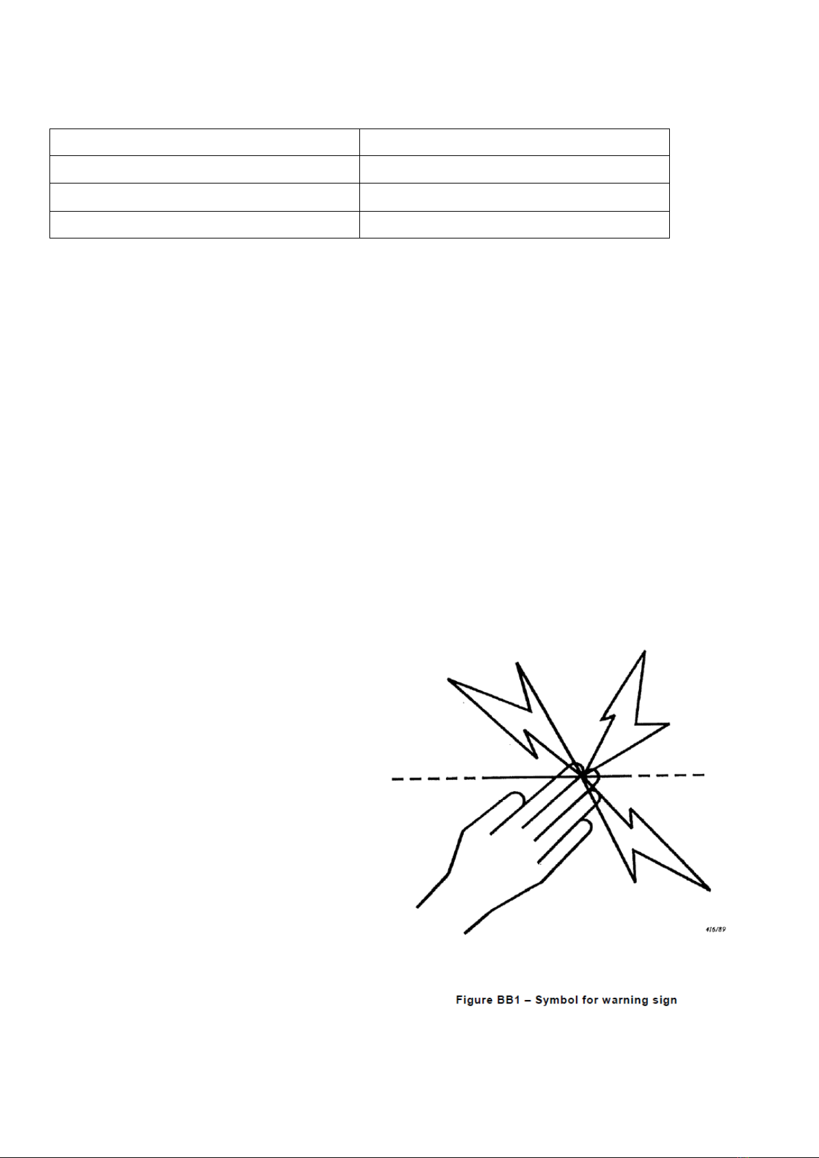
The size of the warning sign shall be at
least 100 mm × 200 mm. The background
colour of both sides of the warning sign
shall be yellow. The inscription on the sign
shall be black and shall be either the
symbol of Figure BB1, or the substance of
“CAUTION: Electric fence”.
15
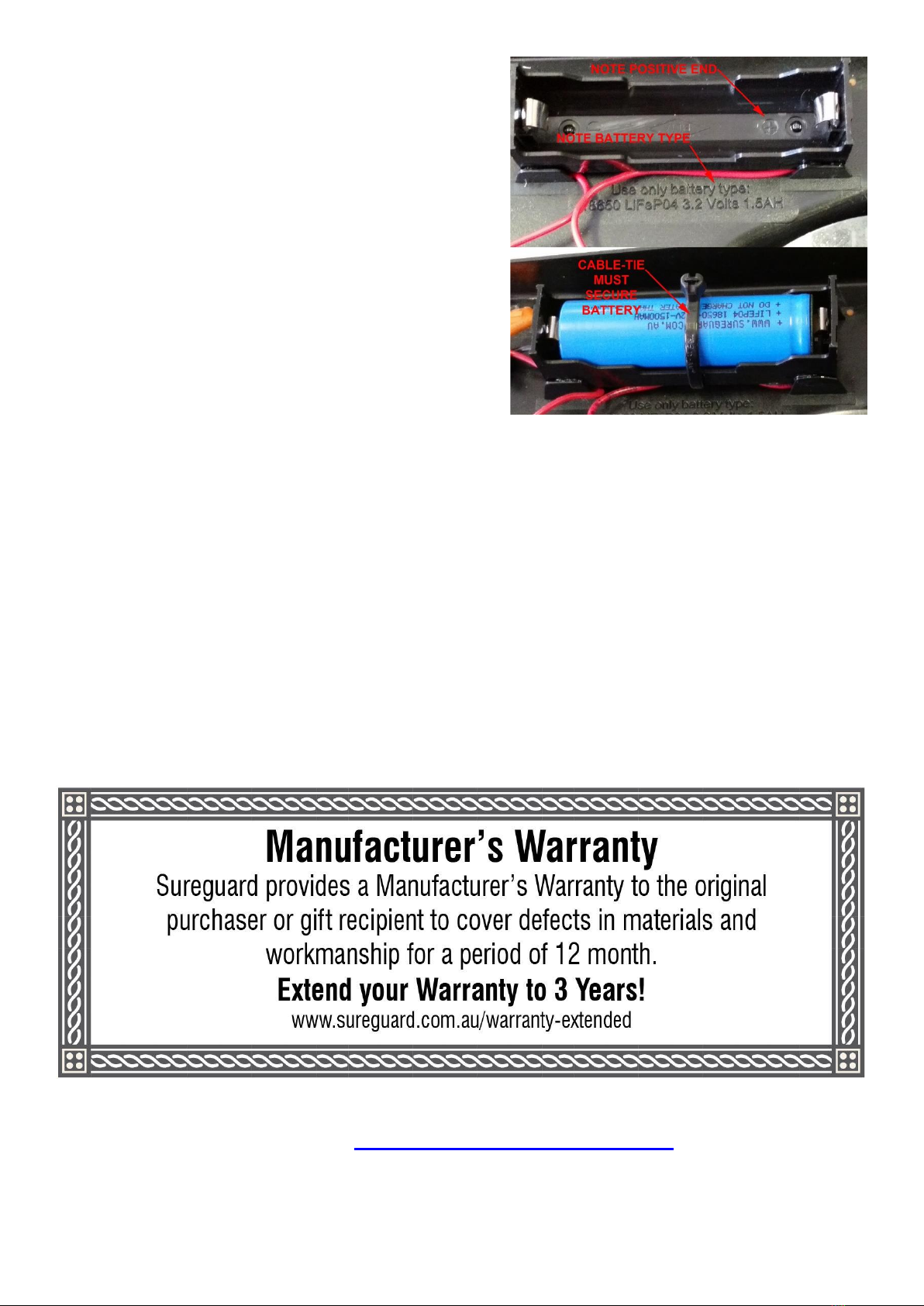
How to Change the Solar Battery
This Energiser uses a particular long-life lithium
battery. You may never need to replace or
remove it. But if you do, open the case by
removing the four case screws. Then ensure that:
1. The replacement battery is type Lithium-Iron-
Phosphate (LiFePO4). This battery has a
voltage of 3.2 volt. DO NOT substitute other
battery voltages because they will NOT
charge. The original battery has an Amp-Hour
rating of 1.8AH, but a larger capacity may be
available in future.
2. Identify the positive end of the battery holder.
Insert the positive end of the battery first then push the negative end down.
3. Do not install damaged batteries.
4. ALWAYS Cable-Tie the battery as illustrated. It is a safety requirement.
Maintenance
1. Regularly check and clean the Solar Panel for dust and bird droppings.
2. Use a damp cloth with a little soap every three months to clean the external rubber
corners. Cleaning reduces mould from taking hold and damaging the rubber.
Full Terms and Conditions at www.sureguard.com.au/terms

Other manuals for Pro-Tech 5
1
Table of contents
Other Sureguard Power Supply manuals


Popular Power Supply manuals by other brands


Rohde & Schwarz
Rohde & Schwarz NGA100 Getting started

elsner elektronik
elsner elektronik KNX PS640 Technical specifications and installation instructions

Oase
Oase 50733 operating instructions

Fryette
Fryette Valvulator I owner's manual

Kemot
Kemot PROsinus-1600 owner's manual

Crestron
Crestron CSA-PWS10S-HUB-ENET installation guide


