Surewerx Strongarm 816B User manual
PROD. NO. 030537
MOD. NO. 816B
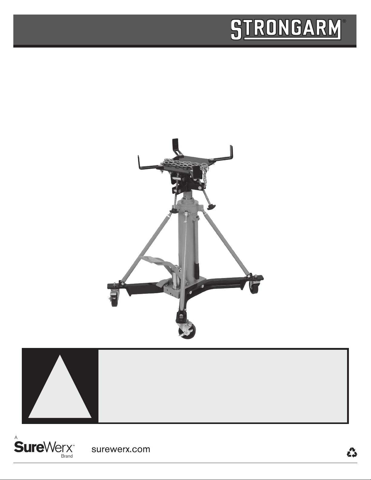
1 Ton High Lift Professional
2-Stage Transmission Jack
Owner’s Manual
WARNING:
Read all instructions and safety warnings before
operating this equipment. Failure to follow the
instructions and safety warnings may result in
personal injury or property damage.
!
M18_SA030537-ENG-FRE_FA

surewerx.com
2
Visually inspect all components for shipping damage. If any shipping damage is found, notify carrier at once. Shipping damage is
NOT covered by warranty. The carrier is responsible for all repair or replacement cost resulting from damage in shipment.
1. Take out all the parts from the wooden box.
2. Assembling the Casters (53/5) to the Legs (48) by using Nut (50) Lock Washer (51) and Washer (52).
3. Assembling the Legs (48) to Pump (36) by using Washer (54) Lock Washer (55) and Bolt (56).
4. Assembling the Support Rod: First, assembling the Adjusted Support Rod (24) to Support Ring (19) by using Bolt (21)
Lock Washer (22) and Nut (23), and making the upper end of Support Ring (19) close to the lower end of Nut (25) (refer to
Fig.1);Then adjusting the length of Round Nut Base (17) and Bolt (26), making the hole of Bolt (26) align to the hole of the
Leg (48)(refer to Fig. 2) and fix the Adjusted Support Rod (24) to Leg (48) by using Lock Washer (22), Nut (23)and Bolt (49),
then tighten the Round Nut Base (17). At last, tighten the Bolt (20)to the Oil Tank (27) Cross Support Ring (19).
5. Assembling the Saddle (57): First loosen Bolt (S19) and take it out, then put Saddle (57) on the Second Piston Rod (7), and
tighten Bolt (S19).
!SETUP
!WARNING!
• The technician using this jack must be trained, qualified, fully familiar with safe work practices, and have prior experience in the use
of hydraulic equipment. Lack of knowledge in any of these areas can lead to equipment damage and/or personal injury.
• Read, understand, and follow all instructions before operating this jack.
• Inspect the jack before each use. Do not use jack if damaged, altered, modified, leaking hydraulic fluid or with missing or loose
components.
• Never modify or weld hydraulic equipment.
• Never lift more that the rated capacity of the jack: overloading causes equipment failure and possible personal injury.
• The jack is a load lifting device, not a load holding device. Once the load is raised, it must always be firmly supported with auxiliary
stands. Never work under or around a load supported only by hydraulic devices.
• Never put unbalanced or off-centre loads on the jack saddle. Use saddle adapters and saddle extenders along with straps and
chains to secure load to the saddle head. Incorrect loading can result in equipment failure.
• This jack was designed for lifting transmissions only. Consult the vehicle manufacturer for the transmission's centre of balance.
• Secure the transmission to the jack’s saddle with the anchorage restraint system provided before raising or lowering the
transmission.
• Use of this product is limited to the removal, installation and transportation in the lowered position. Jack should only be used on a
flat, clean, unobstructed concrete floor.
• Always wear safety glasses and/or other protective equipment that meet or exceed ANSI Z87.1 and OSHA standards.
• Use the jack ONLY on hard, level surfaces capable of sustaining the load.
!WARNING!
1. SERVICE/INSPECTION
Visual inspection shall be performed before each use of this equipment and its adapters, checking for abnormal conditions, such as
cracked welds, leaks, and damaged, loose or missing parts. This equipment shall be removed immediately from service if it is believed
to have been subjected to an abnormal or shock load and shall be inspected by a qualified repair facility. Owners and/or operators
should be aware that repair of this equipment may require specialized knowledge and facilities. It is recommended that this equipment
be inspected annually by a qualified repair facility. Defective parts, decals, safety labels or signs should be replaced with Strongarm
specified parts.
The use of shop equipment is subject to certain hazards that cannot be prevented by mechanical means, but only by exercise of
intelligence, care, and common sense. It is therefore essential to have personnel involved in the use and operation of equipment who
are careful, competent, trained, and qualified in the safe operation of this equipment and its proper use when servicing motor vehicles
and their components. Examples of hazards are dropping, tipping, or slipping of motor vehicles or their components caused primarily by
improperly securing loads, overloading, off-centered loads, use on other than hard level surfaces, and using equipment for a purpose for
which it was not designed. Only Strongarm attachments and/or adapters may be used on this equipment.
The owner and/or operator shall study and understand the product and safety instructions before operating this equipment. Safety
information shall be emphasized and understood. If the operator is not fluent in English, the product and safety instructions shall be
read to and discussed with the operator in the operator’s native language by the purchaser/owner or his designee, making sure that the
operator comprehends their contents. A copy of these instructions/warnings shall be retained for future reference.

surewerx.com 3
!SETUP
OPERATION
!MAINTENANCE
WARNING!
Ensure that you read, understand and apply the safety instructions and warnings before use. Failure to heed these instructions may
result in property damage and/or personal injury.
1. Roll the transmission jack into position and pump the Foot Pedal (35) until saddle reaches desired height.
NOTE: Follow vehicle manufacturer’s recommended procedures for removing the load as outlined in vehicle service
manual or repair guide.
2. Carefully center load on the saddle. Ensure the load's center of gravity is centered on the saddle and the setup is
stable and secure.
NOTE: Before lowering load check to ensure all tools and personnel are clear and it is safe to lower the load.
3. SLOWLY and CAREFULLY operate the Release Pedal (32) to lower the load to its lowest possible position.
4. If necessary, CAREFULLY and SLOWLY move the jack.
5. Transfer load immediately to appropriate support device for service or repair.
1. When not in use, store the jack in a dry location with saddle in lowest position.
2. Periodically check the piston rod for signs of rust or corrosion. Clean exposed areas with a clean oiled cloth.
Warning: Never use sandpaper or abrasive material on these surfaces!
3. A coating of light lubricating oil to pivot points, axles and hinges will help to prevent rust and assure that castors, foot
pedal and pump assemblies move freely. Periodically lubricate the pivot points, axles and hinges with a light lubricating
oil as needed.
4. With jack in its lowest position, remove the Air Vent Screw (25) to check the hydraulic oil level. If it is not adequate, add high
quality hydraulic jack oil as necessary. Insert and tighten the air vent screw. Then purge away air from hydraulic system as
described in purging.
Warning: DO NOT use brake fluid or any other improper fluid and avoid mixing different types of oil when
adding hydraulic oil.
5. To ensure best performance and longer equipment life, replace the complete hydraulic oil at least once a year. With jack in
its lowest position, remove the Air Vent Screw (25), lay the jack on its side and drain the oil into a suitable container. Ensure
that no dirt gets into the system. Set the jack in its level upright position, fill with approved hydraulic jack oil. Then replace
the Air Vent Screw (25) and purge away air from hydraulic system as described in Purging Air.
Note: Dispose of hydraulic oil in accordance with local regulations.
6. When equipment efficiency drops, purge away air from hydraulic system.
7. It is recommended that an annual inspection be done by qualified technicians.

surewerx.com
4
PURGING AIR FROM THE HYDRAULIC SYSTEM
Please follow the instructions to eliminate the air in the pump core if the product is lifting slowly or can’t lift up.
1. Loosen Screw (R33).
2. Press the Release Pedal (R40) when the two pistons (1st stage and 2nd stage) are in the lowest position.
3. Use a 3 mm wrench to loosen M6*8 bleed screw but DO NOT take it off.
4. Operate the Pedal (R43) two or three times until there is hydraulic oil (without bubble) overflow from the hole of bleed screw.
5. At the same time, use a 3 mm wrench to tighten M6*8 bleed screw.
6. Release Pedal (R40) and operate Pedal (R43) to check. Repeat the above steps if the product still doesn’t work.
Please follow the instructions to eliminate the air in the ram if the product is lifting or descending not smoothly.
7. Loosen Screw (R33).
8. Operate Pedal R43 to make the adaptor at the highest position.
9. Use a 4 mm wrench to loosen M6*8 bleed screw but DO NOT take it off.
10. Operate the Pedal (R43) two or three times until there is hydraulic oil (without bubble) overflow from the hole of bleed screw.
11. At the same time, use a 4 mm wrench to tighten M6*8 bleed screw.
12. Press Release Pedal (R40) to make the two pistons retracted. Repeat the above steps again if the pistons are not
retracted normally.
surewerx.com 5
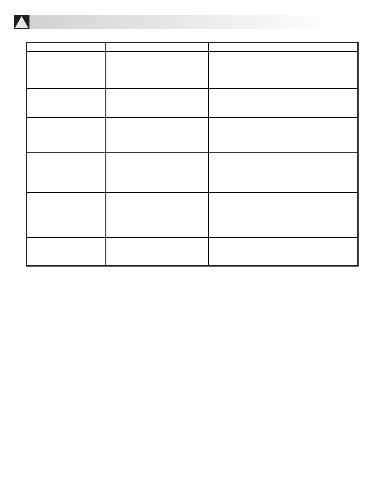
Trouble Possible Reason Solution
Unit fails to lift
1. Not enough oil
2. Air in the hydraulic system
3. Inner leaking
1. Refer to maintenance section and fill to
correct fluid level
2. Refer to Purging Air
3. Contact with the supplier for repair
Unit lifts slowly 1. Air in the hydraulic system
2. Inner leaking
1. Refer to Purging Air
2. Contact with the supplier for repair
Does not lift or
descend smoothly
1. The piston rod needs lubricating
2. Air in the ram
1. Add lubricate oil on the piston rod and work
the piston by one cycle
2. Refer to Purging Air
When offloading, the first
stage piston can be lifted but
the second cannot
1. Not enough oil
2. Air in the ram
1. Refer to Maintenance section and fill to
correct fluid level
2. Refer to Purging Air
When under loading, the first
stage piston can be lifted but
the second cannot
1. Not enough oil
2. Air in the ram
3. Over the max. load
4. Wrong adjustment of
the safety valve
1. Refer to Maintenance section and fill to
correct fluid level
2. Refer to Purging Air
3. Check the weight of the load
4. Contact with the supplier for repair
Unit fails to keep pressure 1. The release pedal doesn’t work well
2. Inner leaking
1. Check the release pedal for any abnormal
2. Contact with the supplier for repair
!TROUBLESHOOTING GUIDE

surewerx.com
6
!PARTS
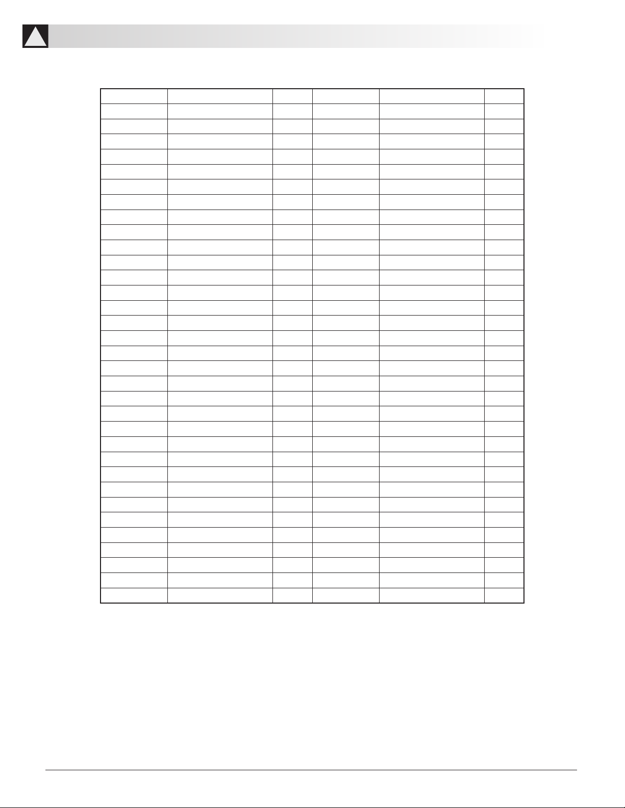
surewerx.com 7
Part No. Description Qty Part No. Description Qty
1 Dust ring 1 34 Ram 1
2 O-ring 1 35 Washer 1
3 Screw 1 36 Pump 1
4 Steel Ball 1 37 U-limited 1
5 Castor 2 38 Lock washer 1
6 Oil cup 1 39 Screw 1
7 Second piston rod 1 40 Release pedal 1
8 Retainer ring 1 41 Pin 1
9 Dust ring 1 42 Washer 2
10 O-ring 1 43 Foot pedal 1
11 Round nut 1 44 Retainer ring 4
12 O-ring 1 45 Connect rod 2
13 First piston rod 1 46 Pin 2
14 Limited ring 1 47 Pin 1
15 Plunger 1 48 Legs 2
16 O-ring 1 49 Bolt 4
17 Round nut base 1 50 Nut 4
18 Waher 2 51 Lock washer 4
19 Support ring 1 52 Washer 4
20 Bolt 1 53 Caster with Brake 2
21 Bolt 4 54 Washer 4
22 Lock washer 8 55 Lock washer 4
23 Nut 8 56 Bolt 4
24 Adjusted support rod 4 57 Saddle 1
25 Nut 4 58 Cotter pin 1
26 Bolt 4 59 U-ring 1
27 Oil tank 1 60 U-ring 1
28 Pin 1 61 Screw 2
29 Cotter pin 3 62 First Limited Valve 1
30 Handle l 63 Pump 1
31 Handle cover 1 64 Steel Ball 1
32 Seal ring 1 65 Spring 1
33 Screw 1
!PARTS LIST

surewerx.com
8
Part No. Description Qty Part No. Description Qty
S01 Bolt 4 S16 AdjustedHandle 2
S02 Block 4 S17 Bolt 2
S03 Plate 1 S18 Cover 1
S04 Washer 4 S19 Bolt 1
S05 Nut 4 S20 Saddle Base 1
S06 Chain Hook 1 S21 Plate Carrier 1
S07 Hook Base 1 S22 Washer 2
S08 Nut 1 S23 Pin2 1
S09 Nut 2 S24 Washer 1
S10 Bear 4 S25 Nut 1
S11 Pin 1 S26 Nut 1
S12 Retainer Ring 4 S27 Washer 2
S13 Pin1 2 S28 Chain 1
S14 Retainer Ring 4 S29 Bolt 1
S15 Cotter Pin 2 S30 Nut 2
!PARTS

surewerx.com 9
Part No. Description Qty Part No. Description Qty
P1 Screw 1 P24 Steel Ball 1
P2 Steel Ball 1 P25 Screw 4
P3 Nut 1 P26 Steel Ball 2
P4 O-Ring 1 P27 Steel Ball Base 1
P5 Pin Cover 1 P28 Spring 1
P6 Dust Cover 1 P29 Screw 1
P7 Dust Plunger 1 P30 Spring 2
P8 Big Pump Core 1 P31 Washer 3
P9 O-Ring 1 P32 Screw 3
P10 Washer 1 P33 Spring 1
P11 Spring 1 P34 Spring 1
P12 Small Pump Core 1 P35 O-Ring 1
P13 Washer 1 P36 Push Rod 1
P14 O-Ring 1 P37 Copper Washer 1
P15 U-Ring 1 P38 Screw 1
P16 Pump Core Base 1 P39 Screw 1
P17 Retainer Ring 1 P40 Screw 1
P18 O-Ring 1 P41 Connector 1
P19 Small Copper Washer 1 P42 Filter 1
P20 Steel Ball 6 P43 First Limited Valve 1
P21 Release Valve Core 1 P44 Pump 1
P22 O-Ring 2 P45 Steel Ball 3
P23 Spring 1 P46 Spring 1
!PARTS LIST
Table of contents
Other Surewerx Lifting System manuals

Popular Lifting System manuals by other brands

Euroscreen
Euroscreen SI-100 Installation and maintenance manual

ATLAS PLATINUM
ATLAS PLATINUM PVL140F-EXT Installation & operation manual

Atlas Escalateurs
Atlas Escalateurs VISTA installation manual

Stannah
Stannah 320 General Installation Instructions

ATH-Heinl
ATH-Heinl Comfort Lift 2.30 a/s operating instructions

Dannmar
Dannmar D4-12 Installation and operation manual


Vestil
Vestil FRA-4-238 quick start guide

Harrington
Harrington CF005 owner's manual

Snorkel
Snorkel MHP15/44 Operator's manual

GORBEL
GORBEL Easy Arm Q2 Series Installation, operation & maintenance manual

Telpro
Telpro Tele-Tower 1177 Operator's manual

Conductix-Wampfler
Conductix-Wampfler SinglePowerLine 0813 Installation instruction