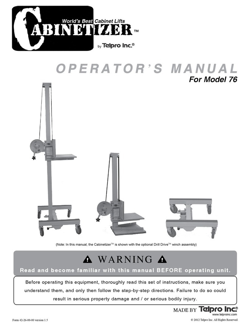
Telpro Tele-Tower 1177 User manual

BEFORE ATTEMPTING TO ASSEMBLE OR USE
the Tele-Tower® Adjustable Work Platform Extension 1177:
1) Thoroughly read and make sure you understand the Operator’s Manual
for the Tele-Tower® Model 1101 Adjustable Work Platform*
2) Thoroughly read this set of instructions, make sure you understand them,
and only then follow the step-by-step directions.
FAILURE TO READ AND FOLLOW THESE INSTRUCTIONS
could result in an incorrectly assembled structure which may fail. Failure of the
structure may result in serious property damage, serious bodily injury and/or death.
All photos in this manual are for illustrative purposes only. Users
should always use appropriate safety devices and personal protective
equipment when engaging in any activity around this equipment.
*All Tele-Tower® manuals are available free from Telpro Inc.
Call Customer Service at 1-800-448-0822 or
701-775-0551 if you need a copy.
A d j u s t a b l e Wo r k P l at fo r m
®
MODEL 1177 EXTENSION
7251 South 42nd St.
Grand Forks ND 58201
www.telproinc.com 1-800-448-0822
Form 42-32-00-00.11-21-02 © 2002, Telpro Inc. All Rights Reserved
OPERATOR’SMANUAL
Read and follow these warnings and the instructions
that follow. Failure to do so may result in serious property
damage, serious bodily injury, and/or death:
WARNING

• Total weight capacity of the Tele-Tower® Adjustable work platform with the 1177
Extension installed is 400 lbs. (181 kg) DO NOT EXCEED THIS LIMIT!
• Inspect the work platform assembly before each use to see that:
• it is assembled correctly
• it is level and plumb
• base outriggers are extended to maintain a height to base ratio in keeping
with applicable standards
• all four casters are securely installed and properly fastened
• all guardrails, chains and sway braces are correctly and securely installed
• safe access is provided
• there are no overhead obstructions or electric lines within 12 feet of the
scaffold assembly
• Always engage all four ladder lock pins before climbing.
• When using the 1177 Tele-Tower® Extension, stand only on the top platform. The lower platform is
not designed as a work area.
• Do not exceed working heights by standing on guardrails, planking guardrails or by use of boxes or
ladders or other devices on the work platform.
• Never make elevation adjustments with a person on the Tele-Tower®.
• Do not ride manually propelled rolling work platform. No personnel should be on the tower while it
is being moved.
• Lock all casters before climbing onto the Tele-Tower®.
• Work only within the platform area: do not try to extend overhead work area by reaching out over
guard railing.
• Do not extend the length or width of the work platform beyond the manufacturer’s supplied design.
• Before moving the work platform:
• Secure all materials
• Be sure oor surface is clear of obstructions or holes
• Be sure there are no overhead obstructions or electric power lines in the
path of rolling work platform.
• Rolling towers must only be used on hard level surfaces.
• Move rolling towers by pushing at the base level only. Do not pull from the top.
Read and follow these warnings and the instructions
that follow. Failure to do so may result in serious property
damage, serious bodily injury, and/or death:
WARNING

To our valued customer:
Thank you for choosing the Tele-Tower® Adjustable Work Platform 1177 Extension Unit.
We are pleased that we are able to provide equipment to make your work easier.
Our efforts are focused on producing the finest quality equipment of which we are capable.
We know that extra time and effort spent on our part to design and produce a high quality finished
product will mean time and effort saved on your part when you use it. This is important to us.
Foundational to all of our work at Telpro Inc. is the fact that God is our creator. It is our desire
to honor Him in our work and business relationships. We are able to provide equipment to ease
only your physical labor. But Jesus said, “Come to me, all who are weary and burdened, and I will
give you rest. Take my yoke upon you and learn from me, for I am gentle and humble in heart,
and you will find rest for your souls. For my yoke is easy and my burden is light.”
Jesus also said, “I have come that they might have life, and have it to the full.” The Apostle Peter
said, “Salvation is to be found through Him alone; in all the world there is no one else whom God
has given who can save us...Leave all your worries with Him because He cares for you.”
Thank you again for giving us the opportunity to work with you. Any questions or comments
that you may have regarding our equipment or company are always welcome.
Telpro Inc.

15-03 15-05
12-00
13-00
15-04
Extension Components
Parts Index
Part # Description
15-03 Complete Extension Ladder (set of 2)
15-05 Extension Coupler Pipes (set of 4)
13-00 Braces (Set of 4)
12-00 Deck
15-04 Turn Buckle Fastening Assembly

Attach hook end to inner telescoping ladder – not
outer ladder. TIGHTEN SECURELY
- NOTE: CHECK TO MAKE SURE THIS ASSEMBLY
REMAINS SNUG DURING USE.
Begin with assembled standard Tele-Tower®
- FULLY EXTEND THE BASE OUTRIGGERS
AND SET CASTER BRAKES.
- REPLACE THE SAFETY RAILS WITH THE
EXTENSION COUPLER PIPES
Place the extension ladders on the coupler pipes with
the turnbuckle fastener on the bottom as shown.
Loosen the turnbuckles on the extension ladders and
turn them down toward the deck.
Position deck on the TOP RUNGS of the extension
ladders only. NEVER position the deck on any of the
lower rungs as this will prevent proper installation of
the anti-sway braces resulting in an unstable structure.
TURNBUCKLE
OUTRIGGERS
STEP 2
STEP 1 STEP 3
STEP 5
STEP 4

Insert the safety rails in the top of the extension ladders.
Attach the bottom of the braces at the bottom of
the extension ladders.
WARNING!! Never operate the Tele-Tower®
without first making sure all braces are properly and
securely installed on the base unit as well as the exten-
sion. Failure to properly install all braces can result in
collapse of the platform possibly resulting in serious
property damage, and/or bodily injury and/or death.
Attach all four braces before using.
(2 of 4 braces shown here.)
Attach the braces to the bottom of the extension deck.
STEP 8
STEP 9
STEP 7
STEP 6

Insert the second set of rails in the top of the first.
Raise deck to desired height by rotating winch
handle in a clockwise direction.
WARNING!!
- ALWAYS LOCK DECK HEIGHT IN POSITION USING
THE LADDER LOCK SPRING PINS. Failure to do so
can result in sudden and unexpected collapse of the
work platform possibly resulting in serious property
damage and/or serious bodily injury and/or death.
Fully extended TELE-TOWER®
with extension provides a
safe 24’ working height.
(17’ 1/2” deck height)
STEP 10
STEP 11
STEP 12
Table of contents
Other Telpro Lifting System manuals
Popular Lifting System manuals by other brands
Noblelift
Noblelift ECL 10 Instruction handbook
ATH-Heinl
ATH-Heinl ATH 4.35 user manual
Blue Giant
Blue Giant U-Series Installation & owner's manual
Oshkosh Corporation
Oshkosh Corporation JLG AE1932 Service maintenance manual
Mohawk
Mohawk TR-33 manual

AFFORDABLE LIFTS
AFFORDABLE LIFTS KCSPM3648 Assembly and installation manual


