Surtek CSS01 Dimensions and installation guide

ATENCIÓN: lea, entienda y siga las instrucciones de seguridad contenidas en este
manual antes de operar esta herramienta.
WARNING: read, understand and follow the safety rules in this manual, before operating this tool.
CSS01
CARETA
ELECTRÓNICA
PARA SOLDAR
ELECTRONIC WELDING
HELMET
MANUAL DE USUARIO Y
GARANTÍA.
USER’S MANUAL AND WARRANTY

2
ENGLISHESPAÑOL
Safety Warnings
Features
Technical data
Operation instructions
Maintenance
Troubleshooting
Warranty policy
Advertencias de seguridad
Características
Especificaciones técnicas
Instrucciones de operación
Mantenimiento
Solucionador de problemas
Garantía
6
6
7
7
8
8
12
3
3
4
4
5
5
12
CONTENIDO CONTENT
SÍMBOLOS SYMBOLS
PELIGRO, ADVERTENCIA, PRECAUCIÓN:
Indica un riesgo personal o la posibilidad de
un daño.
Lea el manual de usuario: lea las instruccio-
nes contenidas en este manual.
DANGER, CAUTION, WARNING: indicates risk of
personal injury and/or the possibility of damage.
Read the user manual: read all the instructions in
this manual.

3
ESPAÑOL•Manual de usuario
CONOZCA SU HERRAMIENTA
CASCO
1. Carcasa del casco.
2. Placa protectora + cubierta frontal del lente.
3. Hebilla de la placa protectora.
4. Perillas para el ajuste de sujeción de cabeza.
FILTRO DE OSCURECIMIENTO AUTOMÁTICO
(dentro del casco)
5. Función de auto-chequeo del filtro de oscure-
cimiento automático.
6. Control interior de sombra variable.
7. Control de sensibilidad mediante perilla (me-
nor a mayor).
8. Control de oscuridad a luz.
9. Cambio de batería.
10. Función de alarma de bajo volúmen.
11. Función de desbaste.
12. LCD.
Filtro de oscurecimiento automático (afuera del casco)
13. Panel solar.
14. Sensores de arco.
15. Filtro UV/IR.
ADVERTENCIAS DE SEGURIDAD
El Casco para Soldar Impulsado por Energía So-
lar con Auto-Oscurecimiento es adecuado para
la mayoría de las aplicaciones de soldadura. El
lente de la careta se oscurecerá automáticamen-
te en 1/ 25 000 segundos al momento de em-
pezar a soldar. Sin importar qué sombra del fil-
tro esté establecida, la protección UV/ IR estará
siempre activa.
• Los rayos emi-
tidos por el arco
de la soldadura
pueden dañar
los ojos y que-
mar la piel
- Antes de soldar,
siempre inspec-
cione el casco y
el Filtro de Oscurecimiento Automático (ADF)
para asegurarse de que estén bien montadas y
en buenas condiciones.
- Mantenga los sensores, celdas solares y lentes
del filtro limpios. Limpie el cartucho de filtro
con una solución de agua con jabón y un paño
suave. No utilice disolventes o detergentes de
limpieza abrasivo.
- No soldar en una posición encima de la cabeza
durante el uso de este casco.
- Inspeccione el lente con frecuencia y reempla-
ce inmediatamente cualquier lente o cubierta
de lente rayada, agrietada o perforada.
- Siempre use gafas de seguridad bajo el casco
de la soldadura, y ropa protectora para proteger
la piel de la radiación, quemaduras y salpicadu-
ras.
CARACTERISTICAS
2
4
15
12
10
14
13
11
3
1
65 7 8 9

4
ESPECIFICACIONES TÉCNICAS
CSS01
CLASE ÓPTICA 1 / 2 / 1 / 3
ÁREA DE VISIÓN 98 X 43 mm
TAMAÑO DE LENTE CUBIERTA
FRONTAL 109,6 x 86 x 1 mm
TAMAÑO DE LENTE CUBIERTA
INTERIOR 103,6 x 48,8 x 0,8 mm
ARCO DEL SENSOR 2
VISIÓN EN ESTADO CLARO DIN 4
VISIÓN EN ESTADO OSCURO
(SOMBRA VARIABLE) 9 - 13
UV/IR PROTECCIÓN DIN 16
VELOCIDAD DE OSCURECIMIEN-
TO 1/ 250000s de claro a
oscuro
OSCURIDAD A LA LUZ 0.1- 1.0 S mediante
perilla
BAJO AMPERAJE TIG ≥5 amps (CD/DC)
≥5 amps (CA/AC)
TEMPERATURA DE OPERACIÓN -5ºC ~ + 55ºC
TEMPERATURA DE ALMACENA-
MIENTO -20ºC ~ + 70ºC
REQUIERE 1 BATERÍA CR2450 DE LITIO INCLUIDA
INSTRUCCIONES DE OPERACIÓN
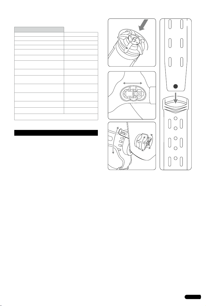
• AJUSTE PARA LA SUJECIÓN DE LA CABEZA
1. Ajuste el diámetro de la sujeción de la cabeza
ajustando la perilla de giro en la parte posterior.
La perilla se desbloquea al presionarla. Una vez
desbloqueado, gire hacia la derecha para apre-
tar y hacia la izquierda para aflojar.
2. Para ajustar la distancia entre la cara del usua-
rio y el filtro de oscurecimiento automático,
afloje las perillas de tensión externas para per-
mitir la sujeción de la cabeza ser reposicionada
a una ubicación diferente. Esto debe hacerse un
lado a la vez y ambos lados se deben colocar el
mismo nivel para la operación adecuada del fil-
tro de oscurecimiento automático.
3. Para ajustar el ángulo de visión, afloje la pe-
rilla y empuje el casco hacia adelante y hacia
atrás a la posición de inclinación deseada. Una
vez que el ángulo es correcto, apriete las perillas
hasta que estén ajustados. El casco todavía debe
girar hacia arriba, pero no debe desviarse hacia
abajo en su lugar para la soldadura.
4. Ajuste la altura presionando el pasador en el
orificio para bloquear en su lugar.
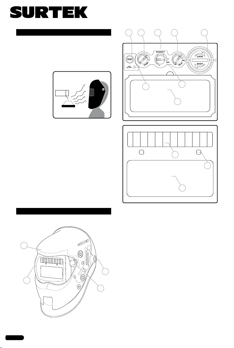
• AUTO-CHEQUEO
Pulse el botón de prueba en cualquier lugar
para ver si cambia automáticamente al estado
oscuro y soltarlo para comprobar que el filtro
vuelve al estado de la luz.
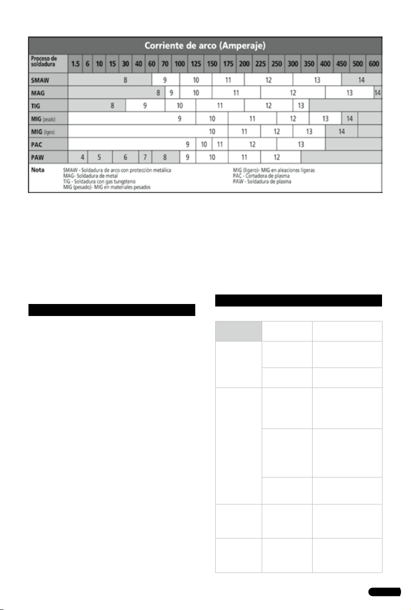
• CONTROL DE OSCURECIMIENTO / MODO
PARA DESBASTE
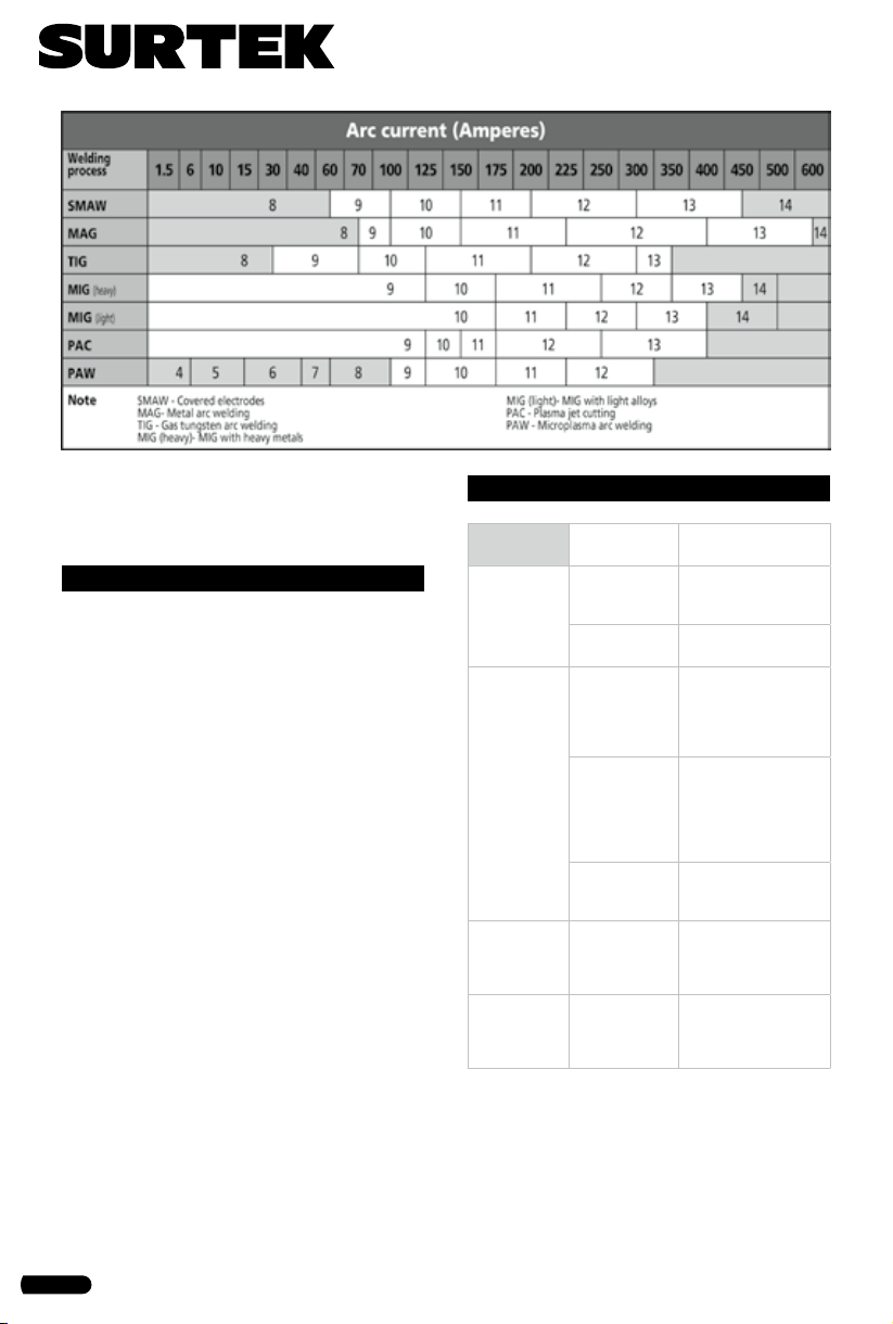
Seleccione la sombra de 9 a 13 en base al pro-
ceso de soldadura que va a utilizar, consulte la
"Tabla Guía de Sombras". La perilla de control
de sombra variable es de ajuste externo. El casco
de soldadura también se puede utilizar para
proteger la cara cuando se desbasta. El modo
para desbaste impide que suceda el auto-oscu-
recimiento en los lentes.
• CONTROL DE RETRASO
Cuando la soldadura cesa, la ventana de visuali-
zación cambia automáticamente de la oscuridad
de nuevo a la luz, pero con un retraso preesta-
blecido para compensar. El tiempo de retardo
se puede ajustar a largo, medio y corto con el
botón interruptor. El corto retraso se adapta a
soldaduras cortas. La larga demora se adapta a
la soldadura fuerte y reduce la fatiga del ojo por
la exposición al arco. La selección media es ade-
cuada para la mayoría de las operaciones de sol-
dadura interior y exterior.
1
3
2
44

5
ESPAÑOL•Manual de usuario
• CONTROL DE SENSIBILIDAD
La sensibilidad se puede configurar en baja-me-
dia-alta con el botón interruptor. El ajuste baja
se adapta al exceso de luz ambiental o con otra
máquina de soldar cerca. El ajuste alta se adecua
a bajo amperaje de soldadura y soldadura en
áreas con condiciones de poca luz, especialmen-
te bajo amperaje de soldadura al arco de argón.
Selección media es adecuada para la mayoría de
las operaciones de soldadura interior y exterior.
MANTENIMIENTO
• REEMPLAZO DEL LENTE DE LA CUBIERTA
FRONTAL
Reemplace el lente de la cubierta frontal si está
dañado (agrietado, rayado, picado o sucio). Co-
loque el dedo o el pulgar en el hueco y flexionar
la lente de la cubierta frontal hacia arriba hasta
que se libere de un borde. A continuación, re-
tire la película protectora antes de instalar una
nueva.
• REEMPLAZO DE LA LENTE DE LA CUBIERTA
INTERIOR
Reemplace la lente cubierta interior si está da-
ñado (agrietado, rayado, picado o sucio). Colo-
que el dedo o el pulgar en el hueco y flexionar
la lente cubierta interior hacia arriba hasta que
se libere de un borde. A continuación, retire la
película protectora antes de instalar una nueva.
• BATERÍAS DE REEMPLAZO
Cuando el indicador de baja tensión cambia a
rojo, se tiene que cambiar la batería. Mueva las
placas de cubierta del filtro de oscurecimiento
automático, gire hacia la izquierda para aflojar
y reemplazar la batería usada con la nueva ba-
tería de litio CR2450. Terminado eso, colocar de
nuevo con las placas de cubierta, girar hacia la
derecha para apretar.
• LIMPIEZA Y ALMACENAMIENTO
Mantenga los sensores, células solares y lentes
de filtro limpios. Limpie el filtro y la cubierta del
casco mediante el uso de una solución de agua
jabonosa y un paño suave. No utilice disolventes
o detergentes de limpieza abrasivos
SOLUCIONADOR DE PROBLEMAS
PROBLEMAS POSIBLES
CAUSAS
SOLUCIÓN SUGE-
RIDA
Dificultad
para ver a
través del
filtro.
La cubierta del
filtro frontal
esta sucia.
La cubierta del filtro
frontal esta sucia.
El filtro esta
sucio.
Limpiar el filtro del
lente.
El filtro no
se oscurece
cuando el
arco esta
funcionan-
do.
Esta seleccio-
nado el modo
para desbastar.
Seleccionar el modo
para soldar y ajustar
el oscurecimiento de
9 a 13.
El panel del
sensor solar
se encuentra
bloqueado.
Asegurarse que los
sensores o el panel
solar estén expuestos
al arco para soldar sin
algún bloqueo.
Se programa
la sensibilidad
muy baja.
Ajustar la sensibilidad
al nivel requerido.
El filtro se
oscurece sin
el arco.
Se programa
la sensibilidad
muy alta.
Ajustar la sensibilidad
al nivel requerido.
El filtro si-
gue oscuro
después de
soldar.
Se programó
delay (retraso)
demasiado.
Ajustar la sensibilidad
al nivel requerido.

6
SAFETY WARNINGS
The Solar-Powered Auto-Darkening Welding
Helmet is suitable for most welding applica-
tions. This helmet’s 1 / 25,000-second switch time
automatically darkens the lens the moment you
start welding. No matter what shade the filter
is set to, the UV/IR protection is always present.
• ARC Rays can
injure eyes and
burn skin
- Before weld-
ing, always in-
spect helmet and
Auto-Darkening
Filter (ADF) to be
sure they are fit-
ted properly and
in good condition.
- Keep the sensors, solar cell and filter lens clean.
Clean the filter cartridge using a soap water
solution and soft cloth. Do not use solvents or
abrasive cleaning detergent.
- Do not weld in the overhead position while us-
ing this helmet.
- Inspect the filter lens frequently and immedi-
ately replace any scratched, cracked, or pitted
filter lens or cover lenses.
- Always wear safety glasses or goggles under
the welding helmet, and protective clothing
to protect your skin from radiation, burns and
spatter.
FEATURES
2
4
3
1
15
12
10
14
13
11
65 7 8 9
KNOW YOUR TOOL
Helmet
1. Helmet Shell.
2. Protective plate + front cover lens.
3. Protective plate buckle.
4. Headgear angle adjusting knobs.
ADF (inside of helmet)
5. ADF self-check.
6. Internal variable shade control.
7. Dial knob sensitivity control (low to high).
8. Delay control knob.
9. Battery change.
10. Low voltage indicator.
11. Grinding function.
12. LCD.
ADF (outside of helmet)
13. Solar Panel.
14. Arc Sensors.
15. UV/IR Filter.

7
ENGLISH•User's Manual
TECHNICAL DATA
CSS01
OPTICAL CLASS 1 / 2 / 1 / 3
VIEWING AREA 98 X 43 mm
FRONT COVER LENS 109,6 x 86 x 1 mm
INSIDE COVER LENS 103,6 x 48,8 x 0,8 mm
ARC SENSOR 2
LIGHT STATE DIN 4
DARK STATE (VARIABLE SHADE) 9 - 13
UV/IR PROTECTION DIN 16
SWITCHING TIME 1/ 250000s from light
to dark
DARK TO LIGHT 0.1- 1.0 S by infinitely
dial knob
LOW AMPERAGE TIG ≥5 amps (CD/DC)
≥5 amps (CA/AC)
OPERATING TEMPERATURE -5 ºC ~ +55 ºC
STORING TEMPERATURE -20 ºC ~ +70 ºC
1 CR2450 LITHIUM BATTERY INCLUDED
OPERATION INSTRUCTIONS
• HEADGEAR ADJUSTMENT
1. Adjust the headgear diameter with the twist
knob on the back. The knob is unlocked until
pushed in. Once unlocked, twist clockwise to
tighten and counterclockwise to loosen.
2. To adjust the distance between the user’s face
and ADF, loosen the outside tension knobs to
allow for headgear to be repositioned to a di-
fferent location. This should be done one side
at a time and both sides should be located the
same for proper auto-darkening filter opera-
tion.
3. To adjust the viewing angle, loosen the knob
and push the helmet forward and back to the
desired tilt position. Once the angle is correct,
tighten the knobs until snug. The helmet should
still swing up, but it should not drift downward
when in place for welding.
4. Adjust the height by snapping the pin into
the hole to lock securely in place.
• SELF-CHECK
Press the TEST Button anywhere to see if it au-
tomatically switches to dark state and release it
to check that the filter returns to the light state.
• SHADE CONTROL/GRIND MODE
Select the shade 9 to 13 based upon the welding
process you will use by consulting the “Shade
Guide Table”. The variable shade control knob
is near inside cover lens for internal adjustment.
The welding helmet can also be used to protect
the face when grinding. Grind mode prevents
filter lens from auto-darkening.
• DELAY CONTROL
When welding ceases, the viewing window au-
tomatically changes from dark back to light but
with a pre-set delay to compensate. The delay
time can be set to MIN (0.1 sec) or MAX (1.0 sec),
by infinitely dial knob inside the cartridge. The
minimum delay suits spot or short welds. The
maximum delay suits heavy current welding
and reduces eye fatigue from the arc. Selections
between MIN and MAX are suitable for most of
indoor and outdoor welding operations.
• SENSITIVITY CONTROL
The sensitivity can be set to LOW or HIGH by
using the infinitely dial knob on the back of the
cartridge. The LOW setting suits excess ambient
light or with another welding machine close by.
The HIGH setting suits low amperage welding
and welding in areas with low light conditions,
especially low amperage argon arc welding. Se-
1
3
2
44

8
lections between LOW and HIGH are suitable
for most of indoor and outdoor welding ope-
rations.
MAINTENANCE
• FRONT COVER LENS REPLACEMENT
Pull the retaining clip outward so the clip slips
out from beneath the retaining tabs. Swing the
retaining clip up and out of the way. Lift the
ADF and remove it. Take the old front cover lens
out, and remove any protective film before ins-
talling the new one.
• INSIDE COVER LENS REPLACEMENT
Replace the inside cover lens if it is damaged
(cracked, scratched, pitted or dirty). Place your
finger or thumb into the recess and flex the insi-
de cover lens upwards until it releases from one
edge. Then remove any protective film before
installing the new one.
• BATTERIES REPLACEMENT
When low voltage indicator turns red, you have
to change battery. Move cover plates on ADF,
twist counterclockwise to loosen and replace
the old battery by CR2450 lithium battery. Af-
ter that, put on cover plates, twist clockwise to
tighten.
• CLEANING AND STORING
Keep the sensors, solar cell and filter lens clean.
Clean filter cartridge and helmet shell by using a
soapy water solution and soft cloth. Do not use
solvents or abrasive cleaning detergent. Switch
the product to Grind Mode and put it in a clean,
dry location for storage.
TROUBLESHOOTING
Problems Possible
causes
Suggested solu-
tions
Difficult to
see through
filter.
Front cover
lens dirty.
Clean or replace front
cover lens.
Filter lens
dirty. Clean filter lens.
Filter does
not darken
when arc is
struck.
Grind mode
selected.
Select weld mode and
adjust Shade from 9
to 13.
Sensors or
solar panel
blocked.
Make sure sensors
or solar panel are
exposed to weld arc
without blocking.
Set sensitivity
to LOW.
Adjust sensitivity to
required level.
Filter
darkens
without
arc.
Set sensitivity
to HIGH.
Adjust sensitivity to
required level.
Filter
remains
dark after
welding.
Set delay to
MAX.
Adjust sensitivity to
required level.

9
Manual de usuario • User’s manual
Notas / Notes

10
Notas / Notes

11
Manual de usuario • User’s manual
Notas / Notes

12
CSS01
URREA HERRAMIENTAS PROFESIONALES S.A.
DE C.V. Warranties this product for a period of 10
years in its parts, components and manual labour
against any manufacture defect from the purchas-
ing date.
Purchase date: ____/____/____
Product:____________________
Brand:______________________
Model:______________________
______________________________
Distributor seal and signature
Sold and Imported by:
URREA HERRAMIENTAS PROFESIONALES S.A. DE
C.V. Carretera a El Castillo, km 11.5, C.P. 45680,
El Salto, Jalisco, México. R.F.C. UHP900402Q29.
Terms:
In order to make warranty effective you must pres-
ent the product along with the warranty properly
filled and signed to an authorized distributor or
service center.
Present the invoice or ticket with official registra-
tion info of the trade from where the product was
purchased. The guarantee is effective as of the date
of purchase stated on the invoice or ticket; or with
the distributor’s stamp (with delivery date in this
policy).
URREA HERRAMIENTAS PROFESIONALES S.A.
DE C.V. Will cover the transportation cost related
to the warranty.
This warranty is not applicable in the follow-
ing cases:
· When the product has not been used according to
normal conditions or natural wear of its parts.
· When the product has not been used according
with this user’s manual instructions.
· When the product has been fixed or modified by
unauthorized or unqualified person.
URREA HERRAMIENTAS PROFESIONALES S.A.
DE C.V. garantiza este producto por el termino de
10 años en sus piezas, componentes y mano de obra
contra cualquier defecto de fabricación a partir de
la fecha de entrega.
Fecha de venta: ____/____/____
Producto: ___________________
Marca: ______________________
Modelo: ____________________
______________________________
Sello y firma de distribuidor
Comercializado e Importado por:
URREA HERRAMIENTAS PROFESIONALES S.A. DE
C.V. Carretera a El Castillo, km 11.5, C.P. 45680,
El Salto, Jalisco, México. R.F.C. UHP900402Q29.
Condiciones:
Para hacer efectiva la garantía deberá presentar
el producto junto con la póliza de garantía debi-
damente firmada y sellada por el establecimiento
donde la adquirió, en cualquiera de los centros de
servicio autorizados.
Presentar la factura o ticket con datos fiscales del
comercio de donde se adquirió el producto. La ga-
rantía cuenta a partir de la fecha de la nota o factu-
ra de compra o el sello con fechador del distribuidor
(con fecha de entrega en esta póliza).
Los gastos de transportación que se deriven del
cumplimiento de la garantía serán cubiertos por:
URREA HERRAMIENTAS PROFESIONALES S.A.
DE C.V.
Esta garantía no será valida en los siguientes
casos:
· Cuando el producto haya sido utilizado en condi-
ciones distintas a las normales o al desgaste natural
de sus partes.
· Cuando el producto no haya sido operado de
acuerdo al instructivo de uso que lo acompaña.
· Cuando el producto haya sido alterado o reparado
por personas no autorizadas.
ESPAÑOL
PÓLIZA DE GARANTÍA
ENGLISH
WARRANT POLICY
Table of contents
Languages: