Suzuki LT-F500FK7 Reference manual

MOTORCYCLE
DATE:
June. 7, 2006
PAGE:
1 OF 12
SUBJECT:
SERVICE INFORMATION
APPLICABLE MODEL:
LT-F500FK7
EFFECTIVE ENGINE OR FRAME NO.:
5SAAM44A 77100001 –
REFERENCE:
P-24, 28, 33
CONTENTS
This bulletin is to inform you of the service information for the above model.
Please use the following service manual along with the information contained in this bulletin
for properly servicing.
LT-F500F Service Manual: 99500-44052-01E
99500-44052-01F
LT-F500F Service Manual CD-ROM: 99560-44050-01E
We hope that this information will be useful in your service activities.
PAG E
SPECIFICATIONS...................................................................................... 2
SERVICE DATA ......................................................................................... 3
FRONT BRAKE HOSE ROUTING........................................................... 11
REAR BRAKE HOSE ROUTING ............................................................. 12
NOTE:
The specifications and service data are same as K6 model.

– 2 –
SPECIFICATIONS
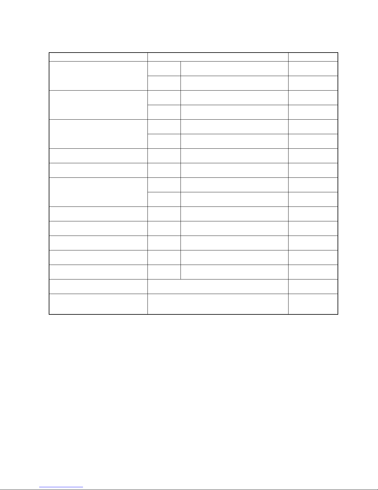
DIMENSIONS AND DRY MASS
Overall length ...................................................................................... 2 095 mm (82.5 in)
Overall width........................................................................................ 1 170 mm (46.1 in)
Overall height ...................................................................................... 1 235 mm (48.6 in)
Wheelbase .......................................................................................... 1 270 mm (50.0 in)
Ground clearance................................................................................ 250 mm (9.8 in)
Seat height .......................................................................................... 860 mm (33.9 in)
Dry mass ............................................................................................. 274 kg (604 lbs)
Front track ........................................................................................... 940 mm (37.0 in)
Rear track............................................................................................ 930 mm (36.6 in)
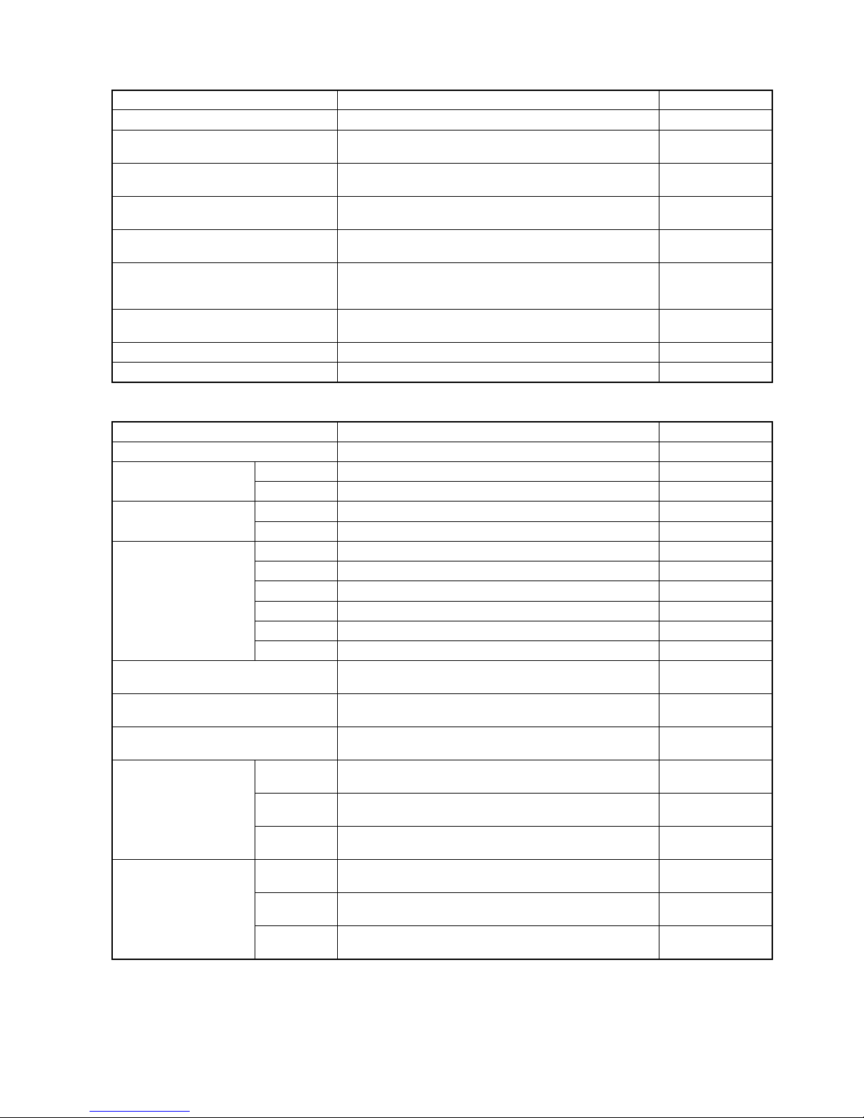
ENGINE
Type..................................................................................................... 4-stroke, liquid-cooled, OHC
Number of cylinders ............................................................................ 1
Bore..................................................................................................... 87.5 mm (3.445 in)
Stroke .................................................................................................. 82.0 mm (3.228 in)
Displacement ...................................................................................... 493 cm3(30.1 cu in)
Compression ratio ............................................................................... 10.2 : 1
Carburetor ........................................................................................... KEIHIN CVK36, single
Air cleaner ........................................................................................... Polyurethane foam element
Starter system ..................................................................................... Electric and recoil starter
Lubrication system .............................................................................. Wet sump
Idle speed............................................................................................ 1 300 ± 100 r/min
DRIVE TRAIN
Clutch .................................................................................................. Wet multi-plate, automatic, centrifugal type
Transmission ....................................................................................... 5-forward constant mesh, 1-reverse with 2-subtransmission
Gearshift pattern ................................................................................. All up, foot lever operated 5-speed constant mesh
Primary reduction ratio ........................................................................ 2.032 (63/31)
Final reduction ratio............................................................................. 4.080 (17/15 × 36/10)
Subtransmission reduction ratio, High............................................... 1.592 (43/27)
Low................................................ 2.419 (22/23 × 43/17)
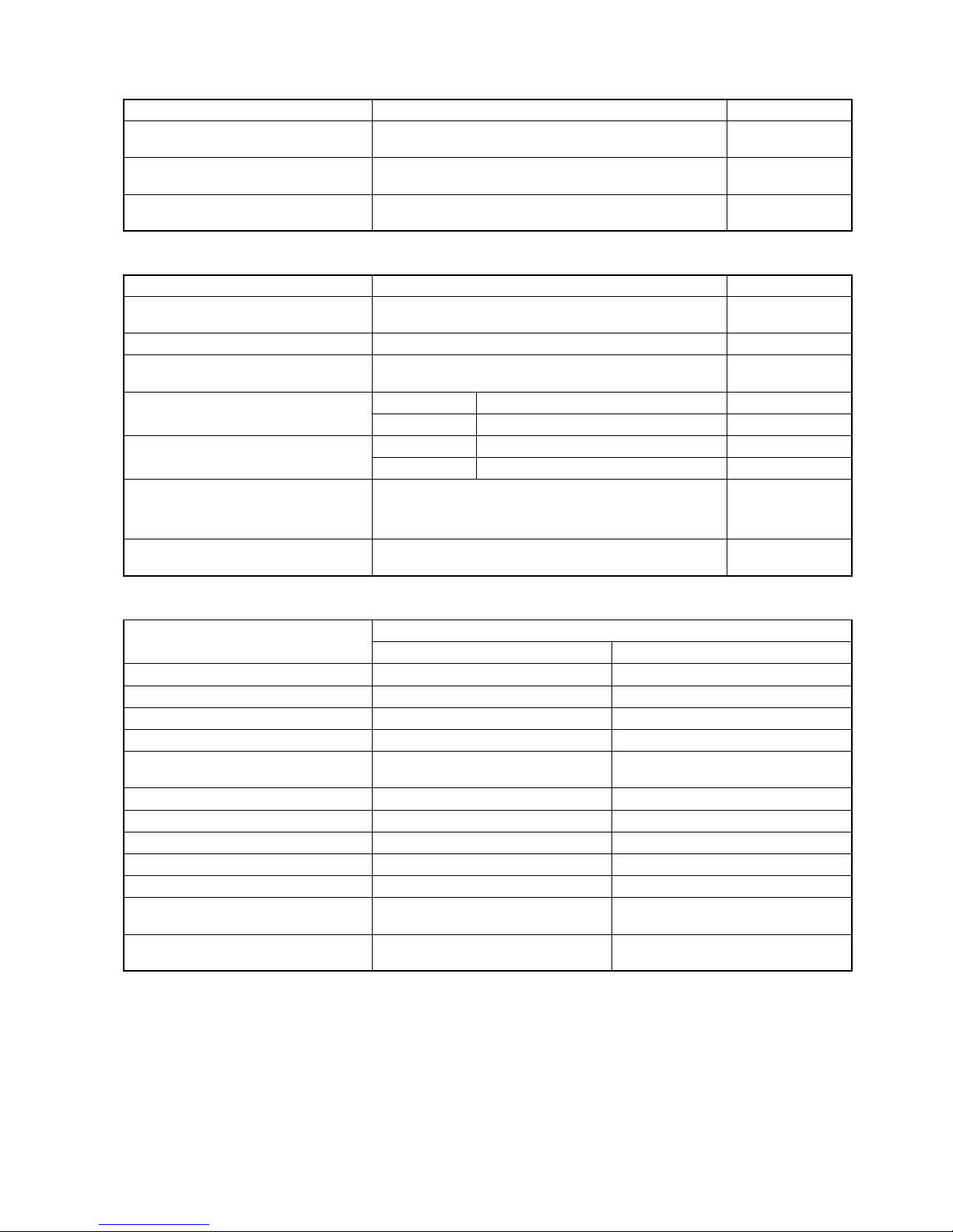
Gear ratios, Low ................................................................................ 3.090 (34/11)
2nd ................................................................................ 1.750 (28/16)
3rd ................................................................................. 1.200 (24/20)
4th ................................................................................. 0.875 (21/24)
Top................................................................................. 0.724 (21/29)
Reverse ......................................................................... 2.636 (29/11)
Drive system........................................................................................ Shaft drive
CHASSIS
Front suspension................................................................................. Independent, double wishbone, coil spring, oil damped
Rear suspension ................................................................................. Swingarm, coil spring, oil damped
Front wheel travel ................................................................................ 180 mm (7.1 in)
Rear wheel travel ................................................................................ 200 mm (7.9 in)
Caster.................................................................................................. 3.3°
Trail...................................................................................................... 17 mm (0.67 in)
Toe-in................................................................................................... 7 mm (0.3 in)
Camber ............................................................................................... 0.45°
Steering angle ..................................................................................... 45°(right & left)
Turning radius...................................................................................... 3.0 m (9.8 ft)
Front brake .......................................................................................... Disc brake, twin
Rear brake........................................................................................... Disc brake
Front tire size....................................................................................... AT25 × 8-12✩✩, tubeless
Rear tire size ....................................................................................... AT25 × 10-12✩✩, tubeless
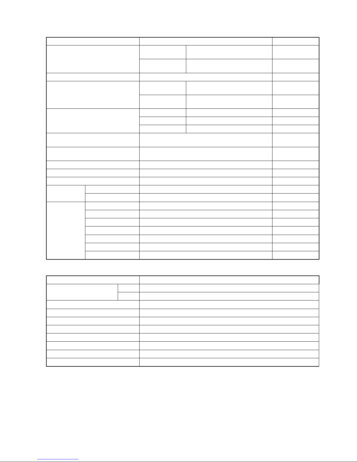
ELECTRICAL
Ignition type......................................................................................... Electronic ignition (CDI)
Ignition timing ...................................................................................... 10° B.T.D.C. at 1 300 r/min
Spark plug ........................................................................................... NGK CR6E or DENSO U20ESR-N
Battery................................................................................................. 12 V 64.8 kC (18 Ah)/10 HR
Generator ............................................................................................ Three-phase A.C. generator
Main fuse............................................................................................. 30 A
Fuse .................................................................................................... 10/10/10/10/10/15 A
Headlight ............................................................................................. 12 V 30/30 W
AUX lamp ............................................................................................ 12 V 40/40 W
Brake light/Taillight .............................................................................. 12 V 21/ 5 W
Speedometer light ............................................................................... LED
Coolant temperature gauge light......................................................... LED
Neutral indicator light........................................................................... LED
High beam indicator light..................................................................... LED
Reverse indicator light......................................................................... LED
Parking indicator light .......................................................................... LED
CAPACITIES
Fuel tank, including reserve................................................................. 19.0 L (5.0/4.2 US/Imp gal)
reserve................................................................................ 4.2 L (1.1/0.9 US/Imp gal)
Engine oil, oil change .......................................................................... 3 400 ml (3.6/3.0 US/Imp qt)
with filter change................................................................ 3 600 ml (3.8/3.2 US/Imp qt)
overhaul............................................................................. 4 000 ml (4.2/3.5 US/Imp qt)
Differential gear oil .............................................................................. 370 ml (12.5/13.0 US/Imp oz)
Final gear oil, overhaul........................................................................ 350 ml (11.8/12.3 US/Imp oz)
Coolant................................................................................................ 2.0 L (2.1/1.8 US/Imp qt)

– 3 –
SERVICE DATA
VALVE + GUIDE Unit: mm (in)
ITEM STANDARD LIMIT
Valve diam. IN. 30.6
(1.20) —
EX. 27.0
(1.06) —
Valve clearance (when cold) IN. 0.05 – 0.10
(0.002 – 0.004) —
EX. 0.17 – 0.22
(0.007 – 0.009) —
Valve guide to valve stem
clearance IN. 0.010 – 0.037
(0.0004 – 0.0015) —
EX. 0.030 – 0.057
(0.0012 – 0.0024) —
Valve stem deflection IN. & EX. — 0.35
(0.014)
Valve guide I.D. IN. & EX. 5.000 – 5.012
(0.1969 – 0.1973) —
Valve stem O.D. IN. 4.975 – 4.990
(0.1959 – 0.1965) —
EX. 4.955 – 4.970
(0.1951 – 0.1957) —
Valve stem runout IN. & EX. — 0.05
(0.002)
Valve head thickness IN. & EX. — 0.5
(0.02)
Valve stem end length IN. & EX. — 1.7
(0.07)
Valve seat width IN. & EX. 0.9 – 1.1
(0.035 – 0.043) —
Valve head radial runout IN. & EX. — 0.03
(0.001)
Valve spring free length
(IN. & EX.) —38.3
(1.53)
Valve spring tension (IN. & EX.) 178 – 206 N
(18.2 – 21.0 kgf, 41.0 – 46.3 lbs)
at length 31.5 mm (1.24 in) —

– 4 –
CAMSHAFT + CYLINDER HEAD Unit: mm (in)
CYLINDER + PISTON + PISTON RING Unit: mm (in)
ITEM STANDARD LIMIT
Cam height IN. 33.430 – 33.498
(1.3161 – 1.3188) 33.130
(1.3043)
EX. 33.500 – 33.568
(1.3189 – 1.3216) 33.200
(1.3071)
Camshaft journal oil clearance Right &
Center 0.032 – 0.066
(0.0013 – 0.0026) 0.150
(0.0059)
Left 0.028 – 0.059
(0.0011 – 0.0023) 0.150
(0.0059)
Camshaft journal holder I.D. Right &
Center 22.012 – 22.025
(0.8666 – 0.8671) —
Left 17.512 – 17.525
(0.6894 – 0.6900) —
Camshaft journal O.D. Right &
Center 21.959 – 21.980
(0.8645 – 0.8654) —
Left 17.466 – 17.484
(0.6876 – 0.6883) —
Camshaft runout —0.10
(0.004)
Rocker arm I.D. IN. & EX. 12.000 – 12.018
(0.4724 – 0.4731) —
Rocker arm shaft O.D. IN. & EX. 11.973 – 11.984
(0.4714 – 0.4718) —
Cylinder head distortion —0.05
(0.002)
Cylinder head cover distortion —0.05
(0.002)
ITEM STANDARD LIMIT
Compression pressure
(Automatic-decomp. actuated) Approx. 1 000 kPa (10.0 kgf/cm2, 142 psi) 800 kPa
(8.0 kgf/cm2,
114 psi)
Piston to cylinder clearance 0.030 – 0.040
(0.0012 – 0.0016) —
Cylinder bore 87.500 – 87.515
(3.4449 – 3.4455) Nicks or
Scratches
Piston diam. 87.465 – 87.480
(3.4435 – 3.4441)
Measure at 15 mm (0.6 in) from the skirt end.
87.380
(3.4402)
Cylinder distortion —0.05
(0.002)
Piston ring free end gap 1st R Approx. 6.2 (0.24) 5.0
(0.20)
2nd R Approx. 12.0 (0.47) 9.6
(0.38)
Piston ring end gap 1st 0.08 – 0.20
(0.003 – 0.008) 0.50
(0.020)
2nd 0.08 – 0.20
(0.003 – 0.008) 0.50
(0.020)

– 5 –
CONROD + CRANKSHAFT Unit: mm (in)
OIL PUMP
ITEM STANDARD LIMIT
Piston ring to groove clearance 1st — 0.180
(0.0071)
2nd — 0.150
(0.0059)
Piston ring groove width 1st 1.30 – 1.32
(0.051 – 0.052) —
2nd 1.01 – 1.03
(0.040 – 0.041) —
Oil 2.51 – 2.53
(0.0988 – 0.0996) —
Piston ring thickness 1st 1.08 – 1.10
(0.042 – 0.043) —
2nd 0.97 – 0.99
(0.038 – 0.039) —
Piston pin bore 23.002 – 23.008
(0.9056 – 0.9058) 23.030
(0.9067)
Piston pin O.D. 22.992 – 23.000
(0.9052 – 0.9055) 22.980
(0.9047)
ITEM STANDARD LIMIT
Conrod small end I.D. 23.006 – 23.014
(0.9057 – 0.9061) 23.040
(0.9071)
Conrod deflection —3.0
(0.12)
Conrod big end side clearance 0.10 – 0.65
(0.004 – 0.026) 1.0
(0.039)
Conrod big end width 24.95 – 25.00
(0.982 – 0.984) —
Crank web to web width 70.9 – 71.1
(2.791 – 2.799) —
Crankshaft runout —0.08
(0.003)
ITEM STANDARD LIMIT
Oil pressure (at 60 °C, 140 °F) Above 120 kPa (1.2 kgf/cm2, 17.0 psi)
Below 160 kPa (1.6 kgf/cm2, 23.0 psi)
at 3 000 r/min —

– 6 –
CLUTCH Unit: mm (in)
DRIVE TRAIN Unit: mm (in) Except ratio
ITEM STANDARD LIMIT
Clutch release screw 1/4 – 2/4 turn back —
Drive plate thickness 2.92 – 3.08
(0.115 – 0.121) 2.62
(0.103)
Drive plate claw width —12.9
(0.51)
Driven plate distortion —0.10
(0.004)
Clutch spring free length —33.8
(1.33)
Clutch wheel I.D. 140.0 – 140.2
(5.512 – 5.520)
Scuffing or
scratch on con-
tacting surface
Clutch shoe —No groove at
any part
Clutch engagement r/min 1 500 – 1 900 r/min —
Clutch lock-up r/min 3 400 – 4 000 r/min —
ITEM STANDARD LIMIT
Primary reduction ratio 2.032 (63/31) —
Final reduction ratio Front 4.080 (17/15 × 36/10) —
Rear 4.080 (17/15 × 36/10) —
Transfer gear ratio Low 2.419 (22/23 × 27/17 × 43/27) —
High 1.592 (43/27) —
Transmission gear
ratio Low 3.090 (34/11) —
2nd 1.750 (28/16) —
3rd 1.200 (24/20) —
4th 0.875 (21/24) —
Top 1.724 (21/29) —
Reverse 2.636 (24/11 × 29/24) —
Shift fork to groove clearance 0.10 – 0.30
(0.004 – 0.012) 0.50
(0.020)
Transfer fork to groove clearance 0.10 – 0.30
(0.004 – 0.012) 0.50
(0.020)
Reverse fork to groove clearance 0.10 – 0.30
(0.004 – 0.012) 0.50
(0.020)
Shift fork groove
width
No. 1 & No. 2
5.5 – 5.6
(0.217 – 0.220) —
Transfer 5.5 – 5.6
(0.217 – 0.220) —
Reverse 5.0 – 5.1
(0.197 – 0.201) —
Shift fork thickness
No. 1 & No. 2
5.3 – 5.4
(0.209 – 0.213) —
Transfer 5.3 – 5.4
(0.209 – 0.213) —
Reverse 4.8 – 4.9
(0.189 – 0.193) —

– 7 –
SHAFT DRIVE Unit: mm (in)
THERMOSTAT + RADIATOR + FAN + COOLANT
CARBURETOR
ITEM STANDARD LIMIT
Secondary drive bevel gear back-
lash 0.05 – 0.15
(0.002 – 0.006) —
Final drive bevel gear backlash 0.08 – 0.13
(0.0031 – 0.0051) —
Front differential drive bevel gear
backlash 0.05 – 0.10
(0.0020 – 0.0040) —
ITEM STANDARD/SPECIFICATION LIMIT
Thermostat valve opening temper-
ature 73.5 – 76.5 °C
(164 – 170 °F) —
Thermostat valve lift Over 3 mm (0.12 in) at 90 °C (194 °F) —
Radiator cap valve opening pres-
sure 95 – 125 kPa
(0.95 – 1.25 kgf/cm2, 13.5 – 17.8 psi) —
Engine coolant temp. indicator light
switch operating temperature OFF →ON Approx. 115 °C (239 °F)
ON →OFF Approx. 108 °C (226 °F)
Cooling fan thermo-switch operat-
ing temperature OFF →ON Approx. 88 °C (190 °F)
ON →OFF Approx. 82 °C (180 °F)
Engine coolant type Use an anti-freeze/coolant compatible with alumi-
num radiator, mixed with distilled water only, at the
ratio of 50:50.
Engine coolant including reserve 2 000 ml
(2.1/1.8 US/lmp qt)
ITEM SPECIFICATION
P-24, 28 P-33
Carburetor type KEIHIN CVK36 ←
Bore size 36 mm ←
I.D. No. 03GH 03GJ
Idle r/min 1 300 ± 100 r/min ←
Float height 17.0 ± 1.0 mm
(0.67 ± 0.04 in) ←
Main jet (M.J.) #128 ←
Jet needle (J.N.) NBAY ←
Needle jet (N.J.) #6 ←
Slow jet (S.J.) #35 ←
Pilot screw (P.S.) 1 and 3/8 turns back PRE-SET
Throttle cable play 3 – 5 mm
(0.12 – 0.20 in) ←
Choke cable play 0.5 – 1.0 mm
(0.02 – 0.04 in) ←

– 8 –
ELECTRICAL
WATTAGE Unit: W
ITEM SPECIFICATION NOTE
Spark plug Type NGK: CR6E
DENSO: U20ESR-N
Gap 0.7 – 0.8
(0.028 – 0.031)
Spark performance Over 8 (0.3) at 1 atm.
Ignition coil resistance Primary 0.1 – 1.5 ΩTerminal –
Ground
Secondary 12 – 22 kΩPlug cap –
Terminal
Generator coil resistance Pick-up 150 – 300 ΩBl – G
Power source 0.05 – 1.0 ΩY – W
Charging 0.1 – 1.5 ΩB – B
Generator no-load voltage
(When engine is cold) More than 60 V (AC) at 5 000 r/min
Generator Max. output Approx. 325 W at 5 000 r/min The rotation of
the generator
Regulated voltage 14.0 – 15.5 V at 5 000 r/min
Ignition coil primary peak voltage More than 150 V +: Bl/W, -: W/B
Starter relay resistance 3 – 5 Ω
Battery Type designation YTX20CH-BS
Capacity 12 V 64.8 kC (8 Ah)/10 HR
Fuse size Main 30 A
Power source 10 A
Headlight (HI) 10 A
Headlight (LO) 10 A
Tail 10 A
Ignition 15 A
Aux 10 A
ITEM SPECIFICATION
Headlight HI 30 × 2 pcs.
LO 30 × 2 pcs.
Auxiliary light 40
Brake light/Taillight 21/5
Speedometer light LED
Reverse indicator light LED
Neutral indicator light LED
Parking indicator light LED
High beam indicator light LED
Engine coolant temp. indicator light LED

– 9 –
BRAKE + WHEEL Unit: mm (in)
ITEM STANDARD/SPECIFICATION LIMIT
Rear brake pedal height 15 – 25
(0.2 – 0.6) —
Brake caliper cylinder bore Front 32.030 – 32.080
(1.2610 – 1.2630) —
Rear 33.960 – 34.036
(1.3346 – 1.3400) —
Brake caliper piston diam. Front 31.948 – 31.998
(1.2578 – 1.2598) —
Rear 33.884 – 33.934
(1.3340 – 1.3360) —
Brake disc thickness Front 3.3 – 3.7
(0.130 – 0.146) 3.0
(0.118)
Rear 3.8 – 4.2
(0.150 – 0.165) 3.5
(0.138)
Brake disc runout —0.30
(0.012)
Master cylinder bore Front 14.000 – 14.043
(0.5512 – 0.5529) —
Rear 12.700 – 12.743
(0.5000 – 0.5017) —
Master cylinder piston diam. Front 13.957 – 13.984
(0.5495 – 0.5506) —
Rear 12.657 – 12.684
(0.4983 – 0.4994) —
Brake fluid type DOT 4 —
Steering angle Right 45° —
Left 45° —
Turning radius 3.0 m (9.8 ft) —
Toe-in (with 75 kg, 165 lbs) 7 ± 4
(0.30 ± 0.16) —
Camber 0.45° —
Caster 3.3° —
Wheel rim size Front 12 × 6.0 AT —
Rear 12 × 7.5 AT —
Tire size Front AT25 8-12 ✩✩—
Rear AT25 10-12 ✩✩—
Tire type Front DUNLOP: KT121D —
Rear DUNLOP: KT405D —
Tire tread depth —4.0
(0.16)
—4.0
(0.16)

– 10 –
TIRE PRESSURE
VEHICLE LOAD CAPACITY LIMIT: 172 kg (380 lbs)
FUEL + OIL
COLD INFLATION
TIRE PRESSURE kPa kgf/cm2psi NOTE
FRONT 35 0.35 5.1 LOAD CAPACITY
UP TO 172 kg (380 lbs)
REAR 30 0.30 4.4
ITEM SPECIFICATION NOTE
Fuel type Use only unleaded gasoline of at least 87 pump
octane (R/2 + M/2) or 91 octane or higher rated by
the research method. Gasoline containing MTBE
(Methyl Tertiary Butyl Ether), less than 10% etha-
nol, or less than 5% methanol with appropriate
cosolvents and corrosion inhibitor is permissible.
Fuel tank capacity including
reserve 19.0 L (5.0/4.2 US/lmp gal)
reserve 4.2 L (1.1/0.9 US/lmp gal)
Engine oil type SAE 10W-40, API SF/SG or SH/SJ with JASO MA
Engine oil capacity Change 3 400 ml
(3.6/3.0 US/lmp qt)
Filter
change 3 600 ml
(3.8/3.2 US/lmp qt)
Overhaul 4 000 ml
(4.2/3.5 US/lmp qt)
Front/Rear drive gear oil type Hypoid gear oil SAE #90,
API grade GL-5
Front drive (differential) gear oil
capacity 270 – 370 ml
(9.1 – 12.5/9.5 – 13.0 US/lpm oz)
Rear drive gear oil capacity 250 – 350 ml
(8.5 – 10.1/8.8 – 10.6 US/lpm oz)

– 11 –
FRONT BRAKE HOSE ROUTING
After touching the brake hose
union to the bottom of reservoir,
tighten the union bolt to the
specified torque.
Brake hose
Throttle cable
B
Starter cable
Rear brake cable
Pass the brake pipe
behind the steering shaft.
Brake pipe
CBrake hose
Brake
caliper (L)
Brake hose
Brake
caliper (R)
AVIEW A
DETAIL B
VIEW D VIEW C
Face the black mar k on the
brake hose to the forward.
Hose guide
After touching the brake hose union
to the stopper, tighten the union bolt
to the specified torque.
Stopper
Stopper
Front brake caliper (R) Front brake caliper (L)
Brake hose
Clamp Clamp
D
Brake hose
Radiator
outlet hose
Pass the brake hose above
the radiator outlet hose.
Cable guide
14
When installing the brake hose,
fix the sleeve of brake hose
to the shape of hose clamp.
Front brake master
cylinder

– 12 –
REAR BRAKE HOSE ROUTING
35˚
77˚
Clip
Stopper
VIEW C
VIEW F
VIEW G
F
VIEW E
VIEW D
VIEW B
VIEW A
After touching the brake hose union to the
stopper, tighten the union bolt to the specified torque.
When installing the brake hose,
fix the sleeve of brake hose to
the shape of hose clamp. Clamp
Brake hose
Outside
Outside
Face the white mark to the outside.
Face the tip of clip to the bottom.
A
G
Fix the brake hose
with the hose guide.
Clamp
Brake hose
B
Face the white mark to the outside.
Rear brake master cylinder
35˚
Pass the brake hose outside of
the brake cable.
Brake
cable
D
C
E
Brake hose
Brake caliper
Brake hose
Fix the brake hose with the clamp.
Fix the brake hose with the hose guide.
Stopper
Rear brake reservoir
Clip
After touching the brake union
to the stopper, tighten
the union bolt to the
specified torque.
Pin
Cotter pin
Table of contents
Other Suzuki Motorcycle manuals

Suzuki
Suzuki GS1000 User manual

Suzuki
Suzuki DL1000 User manual

Suzuki
Suzuki VZR1800K6 User manual

Suzuki
Suzuki TS200R User manual

Suzuki
Suzuki GS500/F User manual

Suzuki
Suzuki 2005 VL800 Manual

Suzuki
Suzuki RM-Z450 User manual

Suzuki
Suzuki Intruder VL800 User manual

Suzuki
Suzuki GSX-R750 User manual

Suzuki
Suzuki VZ1600K4 User guide

Suzuki
Suzuki GSX-F 750 - User manual

Suzuki
Suzuki GSXR-1100 1990 User manual

Suzuki
Suzuki LT-Z400K3 User guide

Suzuki
Suzuki k8 gsx1300r Reference manual

Suzuki
Suzuki shogun sports 125 User manual

Suzuki
Suzuki V-Strom DL650 2017 User manual

Suzuki
Suzuki BANDIT 650 User manual

Suzuki
Suzuki GZ250 1999 User manual

Suzuki
Suzuki DL650 User manual

Suzuki
Suzuki GSX-R750 User manual