FOREWORD
This
outboard
motor
hasbeen
designedand
produced
utilizing
Suzuki's
mostmoderntechnology.
The
finest
product,however,cannot
perform
properly
unless
itis
correctly
assembled
andserviced.
This
set-up
manual
has
been
produced
toaid
you
inproperly
assembling
and
servicing
thisoutboard
motor.
. Thismanual
hasbeen
prepared
on
the
basis
ofthe
latest
specifications
atthetimeofpublication.
lf
modifications
have
beenmadesincethen,
differences
may
exist
between
thecontentofthis
manual
andthe
actualoutboard
motor.
. lllustrations
in
this
manual
areused
toshowthe
basic
principles
of
operation
andwork
procedures
andmay
notrepresent
theactualoutboard
motor
exactly
in
detail.
t This
manual
is
intended
forthosewhohaveenough
knowledge
and
skills
toservice
SUZUKIoutboard
motors.
Without
suchknowledge
andskills,
you
should
not
attempt
servicing
byrelying
onthis
manual
only.lnstead,please
contact
your
nearbyauthorized
SUZUKI
outboard
motor
dealer.
CONTENTS
SYMBOL. ........,.........
I
MATERIALS
REAURED ......,...
1
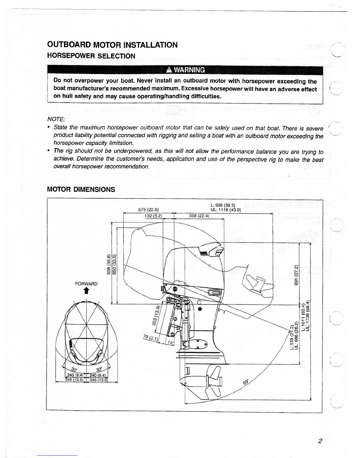
OUTBOARD
MOTOR
INSTALLATION ......2
HORSEqOWER
SELECTTON............. .......,.......
2
MOTOR
DIMENSIONS ,,...2
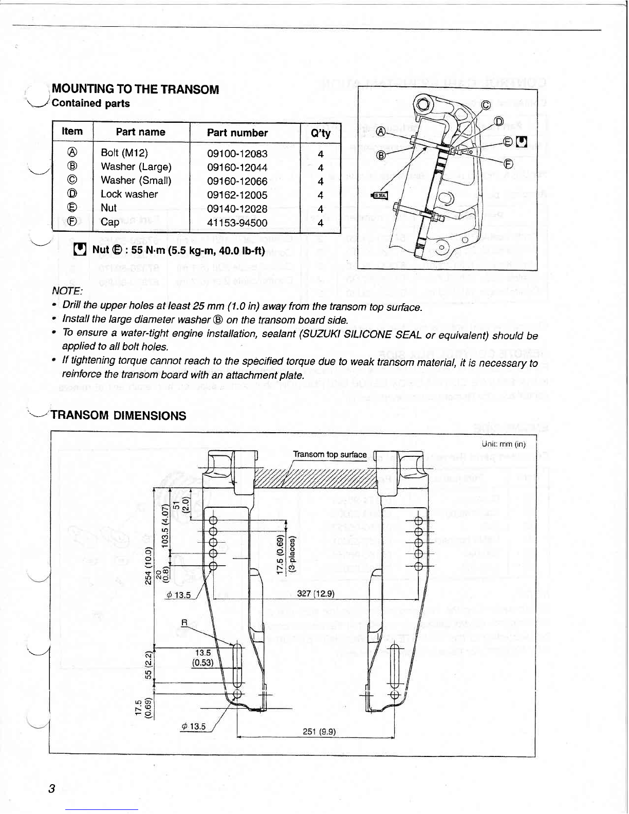
MOUNTING
TOTHETRANSOM .,.....
g
TRANSOM
DTMENSIIONS .................
s
CONT4OL
CABLESINSTALLATTON .......4
REMOTE
CONTROLBOXSiDE .......4
ENGTNE
SIDE ......,............
4
WIRE
HARNESS
INSTALLATION ...........,.
8
DRAG
LINK
TNSTALLATTON .........,-..........
g
couNTERROTAnON
MODEL
ORDUALENGINE,
T\E-ROD
KtT(O?T\ONAL?ARTS)
iN9TALLATION........ ..................
11
INSTALLATION
WITH
THE
PRE-RIGGED
ITEMS
FOR
2 CYCLE
MODEL
............,..
14
wtRtNcDTAGRAM .....,...........
16
WIRING
DIAGRAM
FORDUALENGINE .................
17
SUZUKIMOTOR
CORPORATION
Marine
& Power
products
Division
Apprentice
mechanics
or do-it-yourselfmechanicsthatdon't have
the proper
toolsandequlp-
mentrnay
not beableto properlyperform
theservices
described
inthis manual.
lmproperas-
sembly
and/or
servicing
mayresultin injurytothemechanie
and
mayrender
theengineunsafe
fortheboat
operator
andpassengers.
OCOPYRIGHT
SUZUKI
MOTOB
CORPORATION
2OO1