Swegon TBLZ 2-3-41-2 User manual

GB.ModemIN.120619
www.swegon.com 1
We reserve the right to alter specifications.
Installation instructions for the
TBLZ 2-3-41-2 and TBLZ 2-3-41-1 modem
GOLD
1. General
The SRT DIN 35 and the Siemens MC35i/MC52i modems
are intended to be used for the GOLD RX/PX/CX/SD air
handling units, Version C and D.
The SRT DIN35 is designed the analogue telecom network;
Siemens MC35i/MC52i is designed for the GSM network.
2. Safety precautions
Be careful when you connect various cables to the unit.
Never carry out work while the mains power supply is con-
nected. Doing so may harm the unit. Observe local electri-
cal safety regulations as you install the unit.
Find out before you install the modem whether the SIM
card requires PIN code entry. This will prevent the SIM card
in the GSM modem from locking if an erroneous PIN code
is entered. If that is the case, enter the correct PIN code via
the webpage for the relevant GOLD air handling unit. This
is described in more detail in the Webpage Manual.
3. Analogue modem, SRT DIN 35,
TBLZ-2-3-41-2
3.1 Description
The modem is supplied packaged in a box containing the
following:
1. SRT DIN35 modem with 3-pole power socket
2. Telecom cable. 6/4 RJ11 modular connectors
3. Interface cable. 9-pin D-sub connector modular
connector
4. Telephone plug for Sweden, if a plug for other country
is desired, it must be purchased separately.
5. CD ROM containing complete user’s manual in
Swedish and English.
6. A concise installation manual in English.
The unit consists of:
1. 6 module standard enclosure for DIN rail fastening
IP20.
2. 9-pin D-sub connector for connection via
supplied interface cable for the EIA 232 port of the
GOLD unit.
3. 6/4 pole modular socket for connection to telecom
jack via supplied telecom cable.
4. Power socket for 10-24 V AC/DC,
25 mA at 24V DC supply.
5. LEDs (CD, OH, RxD, TxD, PWR).
The indicating LEDS are described further on in these
instructions.
SRT DIN 35 Analogue modem,
SIEMENS MC35i/MC52i
GSM modem
15
423

GB.ModemIN.120619
2 www.swegon.com We reserve the right to alter specifications.
3.2 Installation
1. Mount the modem on the DIN rail by the control card
of the GOLD unit or in an optional enclosure.
2. Connect the 9-pin D-sub connector to the
appropriate connection socket of the modem.
3. Connect the other end of the interface cable to the
serial port (EIA-232) on the control card of the GOLD
unit.
4. Hand tighten the screws on the EIA-232 connector of
the GOLD unit, to secure them.
5. Connect the telephone plug of the line cord to the
telephone jacks in the wall and the modular connector
to the modular jack of the modem.
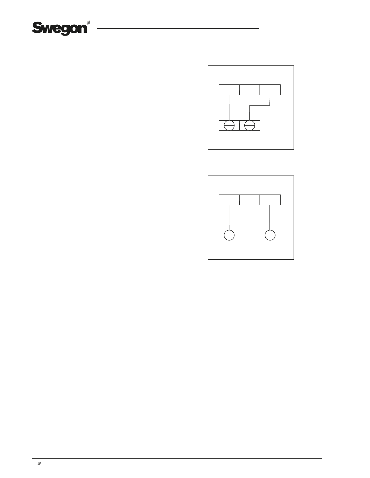
6. Connect terminal 31 and 33, on the modem, to a
separate power supply unit with the correct capacity
or to the 24V AC terminals of the GOLD unit (G=58 or
60, G0=59 or 61, see fig. to the right).
7. Check that the PWR (Power) LED is lit. This indicates
that power is supplied to the modem.
3.3 Status LEDs, SRT 35DIN
There are six LEDs on the front panel of the modem. The
LEDs can be ON, OFF or FLASHING to indicate the opera-
ting status of the modem. The abbreviated captions of the
LEDs are as follows:
PWR Power – Modem is operational
LIT: The power is ON to the modem, but the modem is not
operating.
FLASH: The power is ON to the modem, and the modem is
operating.
OFF: The power is OFF to the modem.
OH Off Hook – Line status
LIT: The line is busy (”the modem is off hook”).
OFF: The modem is on-hook.
CD Data Carrier Detect
LIT: The modem has detected a remote modem carrier and
a data conversation has been made.
OFF: No data connection with a remote modem.
TXD Transmit Data
OFF: No data is being sent.
FLASH: Data is sent to the remote modem or commands
are being sent to your modem (flashing occurs at the rate
of data).
RXD Receive Data
OFF: No data is being received and no commands are
being issued or the modem’s echo-back function is disab-
led.
FLASH: Data is being received from the remote modem or
commands are being echoed back or modem responses to
commands are being indicated (flashing occurs at the rate
of data).
58
59
31 32 33
GG
0
Modem
GOLD,
Control
circuit card
AC power supply
_
+
31 32 33
V+
0 V sig-
naljord
Modem
DC power supply
AC + DC GND

GB.ModemIN.120619
www.swegon.com 3
We reserve the right to alter specifications.
4. GSM modem, SIEMENS MC35i/
MC52i, TBLZ 2-3-41-1
4.1 Description
The modem is delivered in a box containing:
1. Siemens MC35i/MC52i modem
2. Power adapter with plug.
Out: 13,6VDC 600 mA 6/6 pole modular connector.
3. Interface cable 9-pin D-sub (straight serial cable).
4. GSM antenna.
NOTE! The SIM card is not supplied but has to be purcha-
sed separately.
The unit consists of the following components:
1. Modem enclosure.
2. Two holes for screw mounting.
3. 9-pin D-sub for connection via supplied interface cable
for the EIA 232 port of the GOLD unit.
4. 6/6-pin modular connector for voltage feed via
supplied power adapter.
5. Antenna output for connection of supplied GSM-
antenna.
6. Status LED.
7. SIM card holder.
8. Handset audio interface. (not used here).
4.2 Installation
1. Mount the modem by the control card of the GOLD unit
securing it with two screws or in an optional enclosure.
2. Put in the SIM card in the SIM card holder with the
connector surfaces upwards. Push in the holder into
the modem.
3. Fit the antenna cable in intended connector of
the modem.
Fasten the antenna outside the GOLD unit for best
communication.
4. Plug the 9-pin D-sub connector of the interface cable
into the corresponding socket of the modem.
5. Plug the other end of the interface cable into the serial
port (EIA-232) on the control card of the GOLD unit.
6. Hand tighten the screws on the EIA-232 connector of
the GOLD unit and on the modem to secure them.
7. Connect the power adapter to the modem with the
6/6 pole modular connector.
8. Connect the power adapter plug to an appropriate
mains outlet.
9. Check that the status LED is flashing. This indicates
that the power is ON to the modem.
4.3 Status LED on Siemens MC35i/MC52i
ON: The modem is communicating
FLASH: 1 flash/second. The power is ON to the modem,
the modem is searching for the GSM network.
1 flash/3 seconds. The power is ON to the
modem, the modem has contact with the GSM
network and is ready to communicate.
OFF: The power is OFF to the modem.
5 4 3
1
2
768

GB.ModemIN.120619
4 www.swegon.com We reserve the right to alter specifications.
5. Commisioning
Select Protocol, in the EIA-232 Communication menu, to
select GSM modem or analogue modem.
The search path, in the GOLD hand-held micro terminal,
is ”SETTINGS”, “INSTALLATION”,”COMMUNICATION”,
”EIA-232” and ”PROTOCOL”, also see the Operation and
Maintenance Instructions for the GOLD.
After making this selection, the modem will be able to
hook up to the network and transmit data.
IMPORTANT! It might be necessary to make further
adjustments in the e-mail settings of the GOLD unit. These
settings are made on the webpage for the air handling
unit and are described in detail in the instructions for the
air handling unit’s webpage.
IMPORTANT! Only the GSM modem can send SMS mes-
sages. E-mail can be sent both with analogue modem and
with GSM modem.
IMPORTANT! All SIM card/subscriptions do not support
data communication. Check with your GSM operator.
In order to hook up to the unit with the modem and have
access to its webpage, the settings must be as shown in
the menu below (in most cases these values have already
been filled in at the factory):
The GOLD air handling unit‘s settings can be entered by
means of a computer that has been connected by means
of a crossover network cable to the network outlet of
the GOLD air handling unit. The setting for the type of
modem used can be changed from the hand-held micro
terminal or via the webpage. If PIN code check is activated
on the SIM card, the PIN code will also have to be entered
in the ”GSM PIN code” field on the webpage.
When a hook-up with the modem has been established,
write http://10.200.1.3 in the address field in the web
browser. This enables you to go to the webpage of the
GOLD air handling unit. Further particulars on how the
web pages work can be read in the instructions for the air
handling unit’s webpage.
This manual suits for next models
1
Table of contents