3
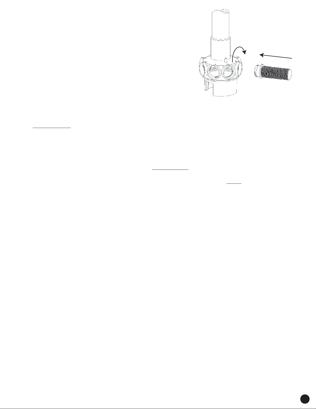
Insert the laterals and turn 90°clockwise.
After hearing the locking sound, the lateral is well installed.
Please refer to the following picture on the right.
3.Check that the air release hose
(Part# 5 / Item# 71624, 71924, or 72224; on Pg. 5).
is xed well on the body of lateral holder, and
that the other end of the air release hose is out of
the sand. DO NOT embed the air release hose in the sand.
4.To eliminate stress on the laterals, ll the lter vessel with
enough water to provide a cushioning eect when the
lter sand is added.
5.Temporarily install the Sand Deector. This is the included piece of clear plastic designed to t on
the top of the sand tank and center, stand pipe (Part# 4 / Item# 71603, 71903, or 72203; on Pg. 5).
It is used to prevent sand from entering the pipe when adding sand to the lter tank.
(PLEASE NOTE: Be sure to remove and store deector in safe place; before connecting the top
mount valve)
6.Carefully pour the sand into the lter vessel and make sure to prevent sand from entering the stem
pipe. Please pour the quantity of sand according to the lter tank label.
7.Ensuring that the lter top mount valve is free of sand residue, put the O-ring on the top valve
mount and then install the valve on the lter vessel. Place the top mount valve on the lter tank so
that the port labeled ‘PUMP’is facing the pump (PLEASE NOTE: This is the port with raised
lettering that says‘PUMP’; to the right side of the port). Make sure that the stem pipe had xed
well with the top valve mount, and tighten the ange clamp to ax the valve. NOTE: The ange
clamp should be well axed. A poorly axed clamp can cause injuries!
8.Using screws from the pump hardware pack, ax the pump to the base. Please reference the pump
installation instructions to operate the pump.
9.Apply Teon tape (included) to the smaller diameter male threaded side of the white double-male threaded
adaptor (part# 10 / 71626; on Pg 5). Attach this adaptor to the port (on the top mount valve) that only has
internal‘female’threading.
10. Adjust the valve position and use the white PVC hose, with installed union nuts, and O-rings (Part #11/ Item
#s 71607, 71907, or 72207; Pg 5) along with white double‘male-threaded’adaptor (attached in step# 9), to
connect the valve to the pump.
11. Apply Teon tape (included) to both threaded hose adaptors and attach one to the port that has raised
letters that say‘RETURN’(on the side; by threading). Connect the included 1.5”x 6’ hose from the top mount
valve to the pools return (inlet jet). This is one of the two ports that has both internal and external threading.
Attach the 2nd threaded hose adaptor to the female threaded opening on the front of the pump. Connect
the 2nd (included) 1.5”x 6’hose from the installed adaptor on the pump to the pools thru-wall skimmer.
12. The nal port is used to connect the drain / outlet / waste hose (NOT INCLUDED). This port has raised letters
that say‘WASTE’(on the side; by threading).
13. Remove, thumb-screw plug, from the top mount valve, that is located on the opposite side from the‘PUMP’
port. Apply Teon tape (included) to the male threads on the provided pressure gauge
(part# 15 / 8961; on Pg 5). Attach pressure gauge to the top-mount valve; where thumb screw plug was
removed.
INSTALLATION NOTES:
1.Make sure the lter is operating under normal working pressure. Use a pressure control valve when
the system pump is operating.
2.If the pump position is higher than the water level, it requires installing a back water control valve.
3.If the pump position is lower than the water level, it requires installing an isolation valve.
Incorrect lter position can interfere or stop water return.
4.For maximum water ow, use as few hose connections as possible & keep hose bending to a minimum.
5.Ensure solvents are not excessively applied to ttings as this could run into O-ring and create sealing
problems.
6.Do not over tighten ttings or adapters.