Swirl 69266 User manual

Product Reference : 69266 (Barcode) (01062922)
33072 (01062939)
79593 (01062946)
87014 (01062953)
Corner Entry Shower Enclosure
Assembly Instructions
Watersmith UK Ltd.,BA22 8RT.

Parts Supplied
Fittings Supplied
AWall Profile
B
Track Frame
( B1)
CFixed Glass
DMoveable
Door
EGasket
(F1)Top Roller
(F2)Bottom
Roller
F
F1a F1bF1c
F1d
F2a F2b F2cF2d
Track
Connector
G
H
I
J
K
Screw Cover
Cap
Wall Profile Cap
(Right and Left)
(I2)
Proflie Splash
Ref Description IIIustration Qty Ref Description IIIustration Qty
Description
Ref IIIustration Qty Description
Ref IIIustration Qty
L
M
N
O
P
Cross Head
Screw
ST4x12mm
Cross Head
Screw
ST4x16mm
Cross Head
Screw
ST4x20mm
Cross Head
Screw
ST4x30mm
Wall Plug
H1 H2
(I1)
Profile Cap
Splash Seal
(Right and Left)
12
Track Frame
( B2)
1
Seal
Corner Entry Shower Enclosure
Assembly Instructions
Watersmith UK Ltd.,BA22 8RT.

Tools Required (not supplied)
Picture
Description Picture Description
Spirit Level
Cross-Head #2 (6mm) Screwdriver
Power Drill (with hammer action)
Rubber Mallet
Silicone Sealant
Tape Measure
Pencil
6mm Drill Bit suitable for type
of wall fixings to be used
3mm HSS Drill Bit
Scissors or Knife
2
Before You Start
·WARNING: Please read these instructions through carefully before you start the
installation. Incorrect product installation may result in serious product failure in use.
Always follow the instructions and retain them for future use.
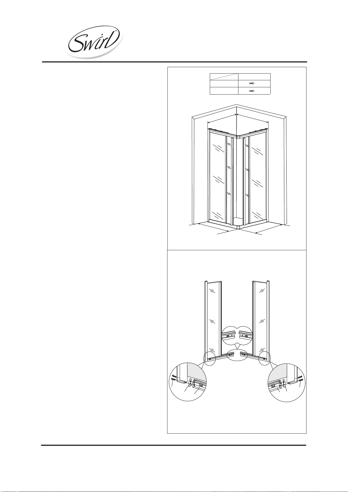
·The enclosure is designed to allow for 20mm adjustment when fitted to "out of true
walls".
· The thickness of the tiles used will affect the overall position of the enclosure on the
tray.
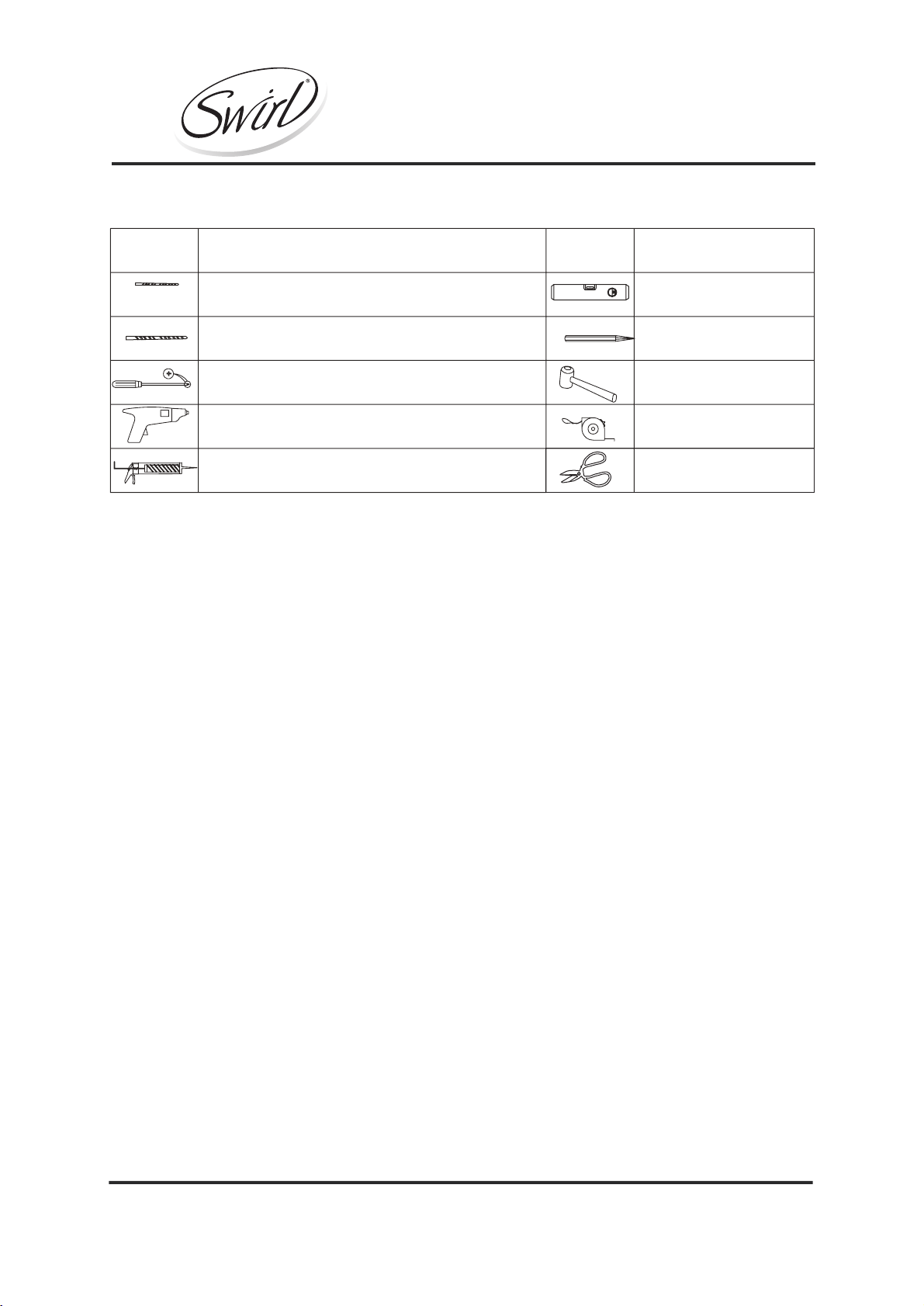
·When you are ready to start, make sure you have the right tools to hand,
plenty of space and a clean dry area for assembly.
·Two people are required for assembly. Please note that although these
instructions are comprehensive, it is always recommended that a technically
competent installer should undertake installation.
·Ensure that the enclosure is fitted to a level tray or floor and vertical walls.
·Please note: The wall plugs included with this product are suitable for solid walls
only. Plasterboard or stud walls may require specialized fixings which are not
provided. (Always ensure that the wall plugs or fittings are correct for the wall type.)
·Caution: Please handle all glass with care. Any damage to the edges, or
scratches to the surface that occur during assembly or normal use can cause
the glass to break suddenly. Tempered glass will shatter into very small pieces
that will still have sharp edges.
·Caution: Care should be taken when drilling into walls to avoid hidden pipes or
electrical cables.
·When working near a tray or bath, ensure that the waste is covered so that small
parts do not fall down it.
Corner Entry Shower Enclosure
Assembly Instructions
Watersmith UK Ltd.,BA22 8RT.

Min. & Max
760x760x1850 730 750mm
800x800x1850 770 790mm
Min. & Max
Min. & Max
Min. & Max
Min. & Max
Assembly
1. Before fixing the shower enclosure,
ensure the shower tray at the base is
properly installed and fully silicone
sealed.
2. Fit the gasket (E) to the end of the
track frame (B1 & B2), and secure them
to the bottom of the fixed glass panels
(C) using screws ST4x20mm (N),
ensuring the correct orientation of the
pre-drilled holes as per Fig.2.
Note: For patter ned glass, always
ensure that the pat tern is on the inside.
C
B1
C
B2
B2
N
EN
E
B1
3
Fig.1
Fig.2
Corner Entry Shower Enclosure
Assembly Instructions
Watersmith UK Ltd.,BA22 8RT.

Fig.3
B1
C
J
3. Insert the profile splash seals (J) into
the channels on the two fixed glass
panels (C). See Fig.3.
Fig.4
4. Fit the gasket (E) to the end of the
of the track frame (B1 & B2), and
secure them to the top of the fixed
glass panels (C) using screws
ST4x20mm (N), ensuring the correct
orientation of the pre-drilled holes as
per Fig.4.
Note: For patterned glass, always
ensure that the pattern is on the
inside.
B1
E
N
B2
B2
C
B2
C
J
B2 E
N
B1
B1
C
4
Corner Entry Shower Enclosure
Assembly Instructions
Watersmith UK Ltd.,BA22 8RT.

B2
B1
C
K
K
K
K
K
B2
B1
M
M
M
5a. Using a sharp knife or scissors,
insert the splash seal (K) tight into the
corner of the fixed glass panel and trim
it to the correct length and shape as
illustrated in Fig.5-1.
Note: Ensure the orientation of the
splash seal is correct when installed.
5b. Repeat the same process for the
joint for the fixed glass (C) and top
track frame (B). See Fig.5-2.
5
Fig.5-1
Fig.5-2
Corner Entry Shower Enclosure
Assembly Instructions
Watersmith UK Ltd.,BA22 8RT.

Fig.6
M
7a. Connect the top and bottom tracks
together using the track connectors (G).
See Fig.7-1.
7b. Use a 3mm HSS drill bit to drill
through the pilot holes on the tracks
into the track connectors (G), taking
care not to drill too far and mark the
outer surface of the track. See Fig.7-2.
7c. Secure the tracks using screws
ST4x12mm (L) and screw cap washers
(H1) and cover with screw caps (H2).
See Fig.7-3.
6a. Using a 3mm HSS drill bit, drill
through the pilot holes in the top and
bottom of the fixed panel seal profile,
through the splash seal (K), into the
top and bottom tracks. See Fig.6.
Note: Take care when drilling so as not
to drill too deep and mark the outer
surface of the top and bottom tracks.
6b. Secure the fixed glass panel to the
top and bottom tracks using screws
ST4x16mm (M). See Fig.6.
GB2
B1
Fig.7-1 Fig.7-2
B1 B2
B2 B1
G
B2 B1
H1
H2
L
H2
L
H1
Fig.7-3
Fig.7
Fig.7-1 Fig.7-2 Fig.7-3
6
Corner Entry Shower Enclosure
Assembly Instructions
Watersmith UK Ltd.,BA22 8RT.

A
A
9a. Place the shower enclosure on the
shower tray, and position it so that there
is an even gap of not less than 10-15mm
to the edge of the tray.
9b. Adjust the two wall profiles so that
they sit flush to the walls, and use a spirit
level to ensure that they are both vertical.
See Fig.9.
8. Insert the two wall profiles (A) into
both side profiles, ensuring the correct
orientation of the flanges as per Fig.8.
7
Fig.8
Fig.9
Corner Entry Shower Enclosure
Assembly Instructions
Watersmith UK Ltd.,BA22 8RT.

Fig.10
P
A
H1 H2O
10a. Taking care not to move the
enclosure, use the pre-drilled holes in
the wall profiles (A) as a template and
mark the hole positions on the wall with
a pencil. See Fig.10.
10b. Remove the enclosure and drill the
holes with a drill bit suitable for the wall
type and fixing being used. Insert the
wall plugs (P) into the holes using a
rubber mallet.
10c. Apply silicone sealant to the back
of the wall profiles (A) and secure them
to the wall using screws ST4x30mm (O)
and screw cap washers (H1). Cover
them with screw cap (H2) as per Fig.10.
Fig.11
11a. Whilst supporting the frame,
carefully insert one corner of the
enclosure over one of the wall profiles
(A) and push it fully home.
11b. Carefully lift the other bottom corner
and fit it over the other wall profile (A).
See Fig.11.
8
Corner Entry Shower Enclosure
Assembly Instructions
Watersmith UK Ltd.,BA22 8RT.

F1a
F1b F1c F1d
D D
Fig.12
F2b
F2a F2c
F2d
Fig.13
13a. Tilt the bottom of the movable
door (D) into the enclosure, and locate
the top rollers in the channel in the top
track frame (B).
13b. Push down on the bottom rollers
and locate them into the channel in the
bottom track frame (B). See Fig 13.
D D
Note: Ensure that the trailing edge
door seal is overlapping with the fixed
panel seal before engaging the bottom
rollers in the track.
12. Fit the top (F1) and bottom rollers
(F2) to the movable glass (D) ensuring
the correct orientation as illustrated in
Fig.12.
Note: For patterned glass, make sure
that the pattern is on the inside.
Outside
Inside
9
Corner Entry Shower Enclosure
Assembly Instructions
Watersmith UK Ltd.,BA22 8RT.

Fig.14
14a. To ensure that the movable doors
(D) are hanging vertically and run
smoothly, adjust the top rollers (F1) by
rotating the screw thread at the bottom.
14b. Raise and lower both of the doors
by adjusting the top rollers as required,
to minimize the gap between the
magnets and the doors run smoothly.
See Fig.14.
Fig.15
I2 I2
15. Fit the wall profile caps (I2) to the
top of the wall profiles (A). See Fig.15.
10
Corner Entry Shower Enclosure
Assembly Instructions
Watersmith UK Ltd.,BA22 8RT.

Fig.16
H1
L
H2
I1 I1
17. Fit the left and right wall profile caps
(I1) to the top of both side profiles. See
Fig.17.
16a. Position the enclosure so that
there is an even gap to the edge of
the tray, and use a spirit level to
ensure the side profiles are vertical.
16b. Taking care not to move the
enclosure, use a 3mm HSS drill to drill
holes through the pilot holes on the
side profiles of the fixed glass (C).
Ensure that you do not drill too far and
mark the outer surface of the profiles.
16c. Secure the profiles using screws
ST4x12mm (L) and screw cap
washers (H1). Cover with screw caps
(H2) as per Fig.16.
11
Fig.17
Corner Entry Shower Enclosure
Assembly Instructions
Watersmith UK Ltd.,BA22 8RT.

18. Apply silicone sealant to the joints
on the outside of the shower enclosure
only, as indicated by the thick line in
Fig.18.
Note: If the silicone is applied to the
inside of the enclosure as well, it can
cause the water to remain trapped and
build up, eventually causing leaks.
Note: Do not use the shower enclosure
for at least 24 hours in order to allow
the silicone sealant to cure fully.
12
Care & Use
·Soapy water is adequate to keep the glass clean, although glass cleaner can be
used if required. Scourers, abrasives and chemical cleaners can damage the
glass and pattern, and should not be used.
·In hard water areas, insoluble lime salts may be deposited on the glass. If this is
allowed to build up it becomes increasingly difficult to remove and looks
unsightly. Regular cleaning will minimize this effect.
Fig.18
24h
Corner Entry Shower Enclosure
Assembly Instructions
Watersmith UK Ltd.,BA22 8RT.
This manual suits for next models
7
Table of contents
Popular Enclosure manuals by other brands

Vantec
Vantec NextStar3 Superspeed user manual

Sans Digital
Sans Digital ELITERAID ER104UT+(B) Detailed user's manual

Boston Acoustics
Boston Acoustics GTuned G210PS Specifications

Pulsar
Pulsar LED/B SATEL Assembly instructions

Mircom
Mircom FleXNet BBX-FXMNSRG installation instructions

StorCase Technology
StorCase Technology Data Express Ultra320 DE100 user guide