Swisher E4-S4000 Owner's manual

E4-S4000
SWISHER OWNER’S/OPERATOR’S MANUAL
E4-S4000 TRIMMER
Part Number 81951 Rev.12/07
Minimize the risk of injury to yourself and others!
Read this manual and familiarize yourself with the
contents. Always wear eye and hearing protection
when operating this unit.
WARNING!

2
Throughout this manual are special “atten-
tion statements”.
IMPORTANT!
The operational procedures described in
this manual are intended to help you get the
most from this unit as well as to protect you
and others from harm. These procedures
are guidelines for safe operation under most
conditions, and are not intended to replace
any safety rules and/or laws that may be
in force in your area. If you have questions
regarding your E4-S4000, or if you do not
understand something in this manual, con-
tact Swisher Inc. at (800) 222-8183, or go
to www.swisherinc.com for assistance. You
may also contact Swisher at the address
printed on the back of this Manual.
Attention StatementsIntroduction
PAGE
The Swisher E4-S4000 hand held power
equipment has been designed and built to
deliver superior performance and reliability
without compromise to quality, comfort,
safety or durability.
Swisher engines represent the leading edge
of high-performance engine technology, deliv-
ering exceptionally high power with remarkably
low displacement and weight. As an owner/op-
erator, you’ll soon discover for yourself why
Swisher is simply in a class by itself!
Attention Statements .................................2
Safety Information......................................3
Safety Labels...............................................4
Product Description...................................5
Specifications..............................................5
Assembly and Adjustments.......................6
Engine Fuel.................................................9
Starting the Engine....................................9
Stopping the Engine ................................10
Adjusting Engine Idle..............................10
Checking Unit Condition.........................11
Shoulder Strap..........................................11
Cutting Grass with a Trimmer Head ......11
Maintenance.............................................12
Long Term Storage..................................15
Troubleshooting Guide ...........................16
Emission System Warranty.....................18
Contents
CAUTION!
A statement preceded by the word
“CAUTION” contains information that
should be acted upon to prevent me-
chanical damage.
WARNING!
A statement preceded by the trian-
gular attention symbol and the word
“WARNING” contains information that
should be acted upon to prevent seri-
ous bodily injury.
WARNING!
The engine exhaust from this product
contains chemicals known to the State of
California to cause cancer, birth defects
or other reproductive harm.
NOTE:
A statement preceded by the word “NOTE”
contains information that is handy to know
and may make your job easier.
IMPORTANT!
A statement preceded by the word
“IMPORTANT” is one that possesses
special signicance.
Read and follow this
operators manual.
Failure to do so could
result in serious injury.
Wear eye and hearing
protection at all times
during the operation
of this unit.
Keep bystanders
at least 50 feet (15 m)
away during operation.
Beware of thrown or
ricocheted objects.
Do not operate this unit with a
blade unless the unit is equipped
with a Swisher-approved
handlebar or barrier.
Always wear a harness when
operating this unit with a blade.
A harness is also recommended
when using trimmer line.
If unit is used as a brushcutter,
beware of blade thrust. A jammed
blade can cause the unit to jerk
suddenly and may cause the
operator to lose control of the unit.
IMPORTANT!
The information contained in this owner’s/
operator’s manual describes units avail-
able at the time of publication.
Swisher reserves the right to make
changes to products without prior notice, and
without obligation to make alterations to units
previously manufactured.

3
WARNING!
Use Good Judgment
ALWAYS wear eye protection to shield
against thrown objects.
NEVER run the engine when transport-
ing the unit.
NEVER run the engine indoors! Make
sure there is always good ventilation.
Fumes from engine exhaust can cause
serious injury or death.
ALWAYS clear your work area of trash
or hidden debris that could be thrown
back at you or toward a bystander.
ALWAYS use the proper cutting tool
for the job.
ALWAYS stop the engine immediately
if it suddenly begins to vibrate or shake.
Inspect for broken, missing or improperly
installed parts or attachments.
General Safety Instructions
The Properly Equipped Operator
Always operate with both hands
rmly gripping the unit.
Wear close-tting clothing to protect legs and arms.
Gloves offer added protection and are strongly
recommended. Do not wear clothing or jewelry that
could get caught in machinery or underbrush.Secure
hair so it is above shoulder level. NEVER wear shorts!
Wear hearing protection
devices and a broad-brimmed
hat or helmet.
Always wear eye protection such
as goggles or safety glasses.
Keep away from the rotating trimmer
line or blade at all times, and never lift a
moving attachment above waist-high.
Wear appropriate footwear (non-skid boots or
shoes): do not wear open-toed shoes or sandals.
Never operate the unit while barefoot!
Keep a proper footing and do
not overreach—maintain your
balance at all times during
operation.
Always make sure the appropriate cutting
attachment shield is correctly installed and in
good condition.
Figure 1
Work Safely
Swisher trimmers operate at very high
speeds and can do serious damage or
injury if they are misused or abused. Never
allowa personwithout trainingor instructionto
operatethis unit!
Stay Alert
You must be physically and mentally fit to
operate this unit safely.
WARNING!
WARNING!
Never operate power equipment of
any kind if you are tired or if you are
under the inuence of alcohol, drugs,
medication or any other substance that
could affect your ability or judgement.
Never make unauthorized attachment
installations. Do not use attachments
not approved by Swisher for use on
this unit.
Always wear a shoulder strap or a harness when
operating a unit equipped with a blade.
NEVER extend trimming line beyond
the length specied for your unit.
ALWAYS keep the unit as clean as
practical. Keep it free of loose vegeta-
tion, mud, etc.
ALWAYS hold the unit rmly with
both hands when cutting or trimming,
and maintain control at all times.
ALWAYS keep the handles clean.
ALWAYS disconnect the spark plug
wire before performing any mainte-
nance work.

4
Safety Labels
Figure 3
IMPORTANT
Safety and Operation Information La-
bels: Make sure all information labels are
undamaged and readable. Immediately
replace damaged or missing information
labels. New labels are available, Contact
Swisher Inc. at (800) 222-8183, or go to
www.swisherinc.com for assistance. You
may also contact Swisher at the address
printed on the back of this Manual.
This label indicates the minimum
distance between front handle
and rear grip per ANSI B175.3.
Be Aware of the Working Environment
Avoid long-term
operation in very hot or
very cold weather.
Make sure bystanders or observers
outside the 50-foot “danger zone” wear
eye protection.
Be extremely careful of
slippery terrain, especially
during rainy weather.
Always make sure the appropriate
cutting attachment shield is correctly
installed.
If contact is made with a hard object,
stop the engine and inspect the cutting
attachment for damage.
When operating in rocky terrain or near
electric wires or fences, use extreme
caution to avoid contacting such items
with the cutting attachment.
Be constantly alert for objects and debris
that could be thrown either from the
rotating cutting attachment or bounced
from a hard surface.
Reduce the risk of
bystanders being struck
by ying debris. Make
sure no one is within 50
feet (15 meters)—that’s
about 16 paces—of an
operating attachment.
Figure 2
50
FEET
E4-S4000

5
Product Description
Using the accompanying illustrations as
a guide, familiarize yourself with this unit
and its various components. See Figure 4.
Understanding your unit helps ensure top
performance, long service life, and safer
operation.
Figure 4
Specications E4-S4000
Dry weight (E4-S4000, less attachments) ..............13.0 lb./5.9 kg
Engine model ...................................................................... SF3410E
Engine type...................................................Power Boost Chamber
Bore x stroke.............................................. 1.5 x 1.2 in./38 x30 mm
Displacement.......................................................... 2.1 cu. in./ 34 cc
Maximum power.......................................................1.4 HP/1.0 kW
@ 8,000 RPM (min-1)
Fuel/oil ratio.............................. 50:1 with ISO-L-EGD or JASO FC
class 2-cycle mixing oil*
Carburetor type................................Walbro WYL, diaphragm-type
Fuel tank capacity .................................................... 23.7 oz./700 ml
Ignition............................................................ One-piece electronic,
program-controlled
Spark plug....................................................................NGK CMR5H
Prior to Assembly
Before assembling, make sure you have all
the components required for a complete
unit and inspect unit and components for
any damage.
Specifications are subject to change without notice.
Air cleaner type ..................................... Non-reversible heavy-duty
filter element
Starting method .......................................................................Recoil
Stopping method............................................................Slide switch
Transmission type.............................Automatic, centrifugal clutch
w/bevel gear
EPA Emission Compliance Period**...........................Category A
** The EPA emission compliance referred to on the emission compliance label
located on the engine, indicates the number of operating hours for which the
engine has been shown to meet Federal emission requirements. Category
C = 50 hours (Moderate), B = 125 hours (Intermediate) and A = 300 hours
(Extended).
nEngine and shaft assembly
nCutting attachment
nKit containing cutting attachment shield
mounting bracket and hardware, this
owner’s/operator’s manual and tool kit
for routine maintenance. Tool kits vary
by model and may include a hex wrench
set, a spark plug/screwdriver combina-
tion wrench, and a spanner.
This unit comes fully assembled with the
exception of the cutting attachment shield
and cutting attachment.
*Swisher E4 engine oil meets or exceeds these specifications
and is recommended for all Swisher products.
WARNING!
Do not make unauthorized modica-
tions or alterations to any of these units
or their components.
E4-S4000 TRIMMER
Outer Tube
Trimmer Head
Grip
Cutting
Attachment Shield
Gear Case
Handle
Throttle
Trigger
Throttle Interlock
Ignition Switch
Fuel
Tank
IMPORTANT!
The terms “left”, “left-hand”, and “LH”;
“right”, “right-hand”, and “RH”; “front” and
“rear” refer to directions as viewed by the
operator during normal operation.

6
3/16-1/4 inch (4-6 mm)
Throttle Free Play
Adjust Throttle Lever Free Play E4-S4000
1. Remove the air cleaner cover by loosen-
ing the two thumbscrews. See Figure 7.
2. Loosen the lock nut on the cable ad-
juster. See Figure 8.
Cable
Adjuster
Assembly and Adjustments
Figure 7
Figure 8
Handle
The throttle lever free play should be ap-
proximately 3/16-1/4 inch (4-6 mm). See
Figure 6. Make sure that the throttle lever
operates smoothly without binding. If it
becomes necessary to adjust the lever free
play, follow the procedures and illustra-
tions that follow.
Figure 6
3. Turn the cable adjuster in or out as
required to obtain proper free play
3/16-1/4 inch (4-6 mm). See Figure 8.
4. Tighten the locknut.
Lock Nut
5. Reinstall the air cleaner cover.
Assembly and Adjustments
251043
Outer Tube
Socket-head Capscrews Handle
Mounting Bracket
Throttle Assembly
Figure 3
1. Position the handle on the outer tube as
shown. See Figure 3.
2. Install the mounting bracket with the
socket head cap screws. Tighten the
screws finger-tight ONLY at this time.
3. Locate the handle in the best position
for operator comfort (usually about 10
inches ahead of the throttle assembly).
4. Secure the handle by alternately tighten-
ing the four socket-head screws in a
diagonal or “criss-cross” fashion.

7
23105
Figure 9
Cutting
Attachment
Shield
Outer
Tube
Socket-
Head Cap
Screw
Bracket
Shim
Clamp
Screw
Shim
Retaining
Nut
Cutting
Attachment
Mounting Plate
Cutting Attachment Shield
Line Cutter
Figure 9A Hex Screws
Nuts
Install the Cutting Attachment Shield E4-S4000
1. Insert the cutting attachment shield
between the outer tube and the cutting
attachment mounting plate. See Figure 9.
WARNING!
NEVER operate the unit without the
cutting attachment shield installed
and tightly secured!
CAUTION!
Make sure the clamp screw and re-
taining nut are securely tightened
before tightening the four socket-head
cap screws.
NOTE:
It may be necessary to loosen the retaining
nut and clamp screw to adjust cutting attach-
ment shield mounting plate.
2. Fit the two shims and the bracket over
the outer tube and loosely install the
four socket-head screws. See Figure 9.
3. Tighten the four socket-head cap screws
to secure the cutting attachment shield.
WARNING!
The line cutter is very sharp. Wear
gloves to protect your hands when
handling.
To Change Position of Line Cutter.
1. Remove the 2 hex screws with a 4mm
hex wrench. See Figure 9A.
2. Rotate line cutter. See Figure 9A.
3. Reinstall the two hex screws and
tighten them securely. NOTE:
Be careful to not lose the 2 nuts in the cutting
attachment shield, they are not captured.
The line cutter can be positioned in 2
positions to obtain different line length for
cutting.
Assembly and Adjustments
E4-S4000

8
IMPORTANT!
Mix only enough fuel for your immediate
needs! If fuel must be stored longer than 30
days and Swisher E4 Engine Oil with fuel
stabilizer is not used, it should rst be treated
with a fuel stabilizer such as STA-BIL™.
Mixing Fuel
1.
Place the trimmer on a flat, level surface.
2. Clear any dirt or other debris from
around the fuel filler cap.
3. Remove the fuel cap, and fill the tank
with clean, fresh fuel.
4. Reinstall the fuel filler cap and tighten
firmly.
Filling the Fuel Tank
CAUTION!
This engine is designed to operate on
a 50:1 mixture consisting of unleaded
gasoline and ISO-L-EGD or JASO FC
class 2-cycle mixing oil only. Use of
non-approved mixing oils can lead to
excessive carbon deposits.
CAUTION!
Never use any type of gasoline con-
taining more than 10% alcohol by vol-
ume! Some types of gasoline contain
alcohol as an oxygenate. Oxygenated
gasoline may cause increased operat-
ing temperatures. Under certain con-
ditions, alcohol-based gasoline may
also reduce the lubricating qualities of
some 2-cycle mixing oils. Generic oils
and some outboard oils may not be
intended for use in high-performance
engines, and should never be used in
your Swisher engine.
nUse only fresh, clean unleaded gasoline
with a pump octane of 87 or higher.
nMix all fuel with a 2-cycle air-cooled mix-
ing oil that meets or exceeds ISO-L-EGD
and/or JASO FC classified oils at 50:1
gasoline/oil ratio.
Examples of 50:1 mixing quantities
n
1 gallon of gasoline to 2.6 oz. mixing oil
n
5 liters of gasoline to 100 ml. mixing oil
Swisher E4 Engine Oil is a registered JASO
FC classified oil and also meets or exceeds
ISO-L-EGD performance requirements.
Swisher E4 engine oil is recommended for
use in all Swisher low emissions engines and
also includes a fuel stabilizer.
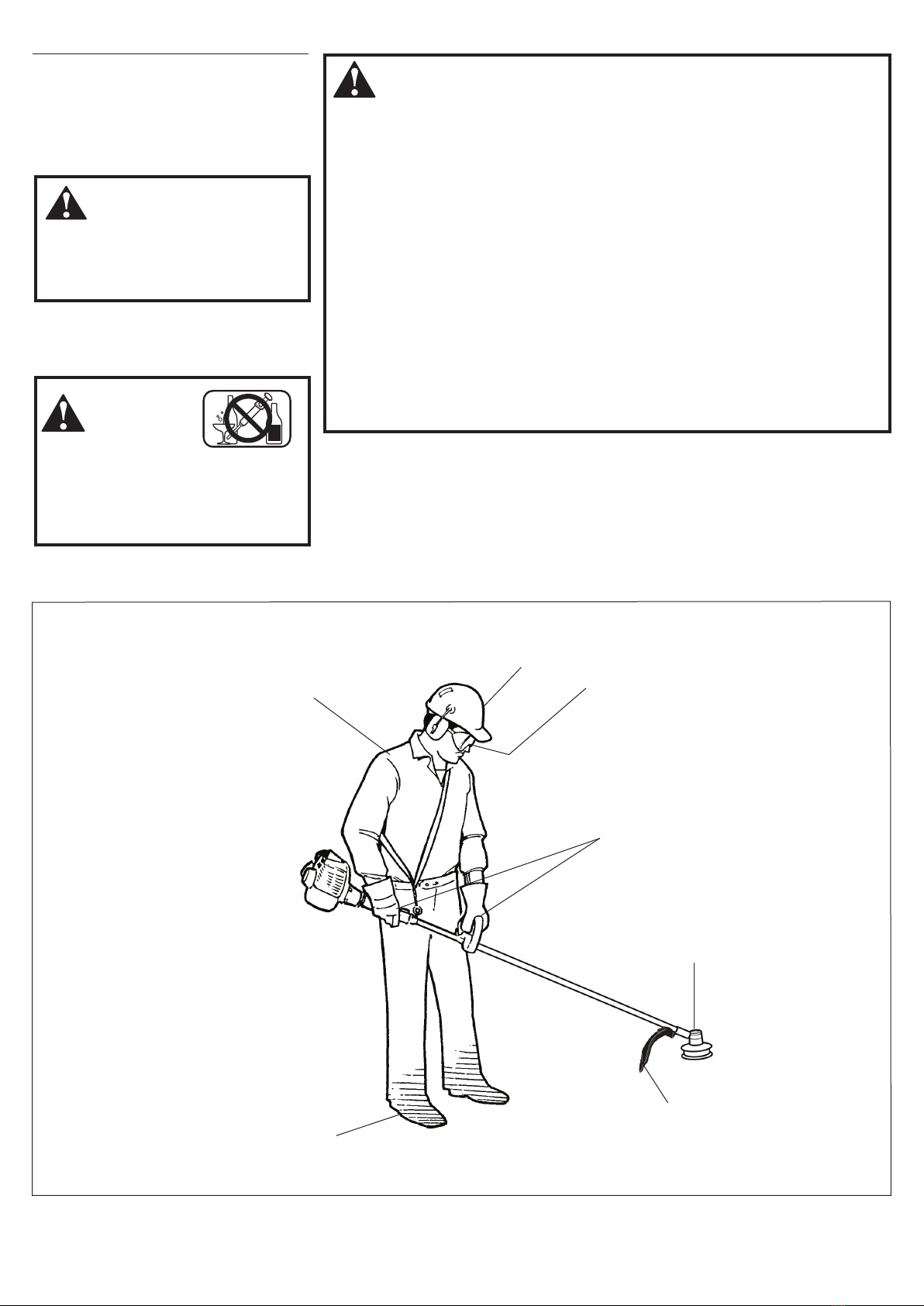
WARNING!
Minimize the Risk of Fire
NEVER smoke or light res near the
engine.
ALWAYS stop the engine and allow
it to cool before refueling. Avoid over-
lling and wipe off any fuel that may
have spilled.
ALWAYS inspect the unit for fuel
leaks before each use. During each
rell, check that no fuel leaks from
around the fuel cap and/or fuel tank.
If fuel leaks are evident, stop using the
unit immediately. Fuel leaks must be
repaired before using the unit.
ALWAYS move the unit at least 10
feet (3 meters) away from a fuel stor-
age area or other readily ammable
materials before starting the engine.
NEVER place ammable material
close to the engine mufer.
NEVER operate the engine without
the mufer and spark arrester screen
in place.
1. Turn the trimmer over so that the gearcase
output shaft faces UP. See Figure 5.
2. Remove and discard the plastic retain-
ing plug.
3. Position the tool holder as shown, and
slide the holder onto the output shaft.
See Figure 5.
4. Rotate the tool holder and shaft until the
notch in the holder aligns with the notch
on the gearcase flange, and use the long
end of the hex wrench to lock the output
shaft in position. See Figure 6.
5. While holding the hex wrench, thread
the trimmer head onto the output shaft,
turning counter-clockwise.
WARNING!
A standard grass trimmer
machine should NEVER be oper-
ated with blade-type attachments.
IMPORTANT!
The trimmer head has a left-hand thread.
Turn the trimmer head counter-clockwise
to install.
6. Using hand pressure only, tighten the
trimmer head firmly on the gearshaft.
See Figure 6.
7. Remove the hex wrench.
Output shaft
Tool holder
Position
attachment
so that the
gearcase
output shaft
faces UP
Figure 5
Hex wrench
Turn trimmer head
COUNTERCLOCKWISE to tighten
Figure 6
Install the Trimmer Head

9
WARNING!
Never start the engine from
the operating position.
WARNING!
The cutting attachment may
rotate when the engine is started!
When the Engine Starts...
After the engine starts, allow the
engine to warm up at idle 2 or 3 min-
utes before operating the unit.
After the engine is warm, pick up the
unit and clip on the shoulder strap.
Advancing the throttle makes the cut-
ting attachment turn faster; releasing
the throttle permits the attachment to
stop turning. If the cutting attachment
continues to rotate when the engine
returns to idle, carburetor idle speed
should be adjusted (see "Adjusting
Engine Idle").
■
■
■
IMPORTANT!
If the engine fails to start after several at-
tempts with the choke in the closed posi-
tion, the engine may be ooded with fuel.
If ooding is suspected, move the choke
lever to open position and repeatedly pull
the recoil starter to remove the excess
fuel and start the engine. If the engine still
fails to start, See the section "Starting a
Flooded Engine" for instructions.
When the engine starts, slowly move the
choke lever to the "OPEN" position. See
Figure 10. (If the engine stops after the
initial start, close the choke and restart.)
Figure 10
Open
Primer Bulb
Return Tube
Starting the Engine
While holding the outer tube firmly with
your left hand, use your other hand to
slowly pull the recoil starter handle until
resistance is felt, then pull quickly to
start the engine.
Make sure the cutting
attachment is clear of
obstructions!
IMPORTANT!
Engine ignition is controlled by a two position switch mounted on the throttle housing labeled, "I" for ON or START and "O" for OFF or STOP.
Figure 6
Figure 7
Figure 9
IMPORTANT!
The primer system only pushes fuel
through the carburetor. Repeatedly
pressing the primer bulb will not ood the
engine with fuel. CAUTION!
Do not pull the recoil starter to the
end of the rope travel. Pulling the
recoil starter to the end of the rope
travel can damage the starter.
ON
Set the throttle lever to the “fast idle”;
Squeeze the throttle lever toward the
hand grip on the shaft tube.
Depress and hold the throttle lock but-
ton.
While depressing the throttle lock button,
release the throttle lever. See Figure 6.
Press the primer bulb until fuel can be seen
flowing in the transparent return tube.
Set the choke lever to the "CLOSED" posi-
tion if engine is cold.
Figure 8
Closed
Throttle Lock
Button
Ignition Switch
Throttle
Trigger
Slide the ignition switch to the “ON” posi-
tion. See Figure 6.
WARNING!
Never start the engine with-
out the tool assembly and cutting
attachments installed to the engine.
Failure to do so could damage the
engine and increase unexpected risk
to the operator and any bystander.

10
341021
Idle the engine briefly before stopping
(about 2 minutes), then slide the ignition
switch to the “O” (Engine OFF) position.
Stopping the Engine
Adjusting Engine Idle
Figure 21
OFF
The engine must return to idle speed
whenever the throttle lever is released.
Idle speed is adjustable, and must be set
low enough to permit the engine clutch to
disengage the cutting attachment.
Idle Speed Adjustment
WARNING!
The cutting attachment must NEVER
rotate at engine idle! If the idle speed
cannot be adjusted by the procedure
described here, return the trimmer to
your Swisher dealer for inspection.
1. Place the trimmer on the ground, then
start the engine, and then allow it to idle
2-3 minutes until warm.
2. If the attachment rotates when the
engine is at idle, reduce the idle speed
by turning the idle adjustment screw
counter-clockwise. See Figure 22.
3. If a tachometer is available, the engine idle
speed should be final adjusted to 3,000
(±300) RPM (min-1).
4. Carburetor fuel mixture adjustments are
preset at factory and cannot be serviced
in the field.
E4-S4000
Figure 22 Idle Adjusting
Screw
NEVER operate the unit with the cut-
ting attachment shield or other protective
devices removed!
WARNING!
A cutting attachment shield or other
protective device is no guarantee
of protection against ricochet. YOU
MUST ALWAYS GUARD AGAINST
FLYING DEBRIS!
Use only authorized Swisher parts and
accessories with your Swisher trimmer. Do
not make modifications to this unit without
written approval from Swisher, Inc.
Checking Unit Condition
ALWAYS make sure the cutting attach-
ment is properly installed and firmly tight-
ened before operation.
NEVER use a cracked or warped cutting
attachment: replace it with a serviceable
one.
ALWAYS make sure the cutting attach-
ment fits properly into the appropriate
attachment holder. If a properly installed at-
tachment vibrates, replace the attachment
with new one and re-check.
ALWAYS stop the engine immediately and
check for damage if you strike a foreign
object or if the unit becomes tangled. Do not
operate with broken or damaged equipment.
NEVER allow the engine to run at high
RPM without a load. Doing so could dam-
age the engine.
NEVER operate a unit with worn or dam-
aged fasteners or attachment holders.

11
Hold the trimmer so the trimmer head is
angled slightly into the area to be cut. To
ensure maximum trimmer-line service life,
cut only with the tip of the trimmer line.
Cut grass by swinging the trimmer from
left to right. Keep the trimmer head hori-
zontal. See Figure 24.
Edging
Tilt the handle
about 100° to the
left (from hori-
zontal) and move
forward, holding
the trimmer verti-
cally as shown in
Figure 25.
341024
Your Swisher unit may be equipped with
one of several Swisher trimmer head mod-
els, each with features for specific applica-
tions and/or operational requirements.
NOTE:
For proper operation, always refer to the
instructions accompanying the trimmer head
being used. Available trimmer head styles
include:
nSemi-automatic. Trimmer line is
indexed when the operator taps the
trimmer head on the ground during
operation.
nManual. The operator indexes line man-
ually with the grass trimmer stopped.
nFixed. The operator must stop the unit
and add new lengths of trimmer line
manually.
nFlail. This device, designed for clearing
weeds and light brush, features three
nylon blades attached to the head by
pivots.
NOTE:
Additional hardware may be required to
mount the Fixed Line or the Flail type trim-
mer heads.
Cutting Grass—Units equipped with a trimmer head
CAUTION!
Operation at low RPM can lead to pre-
mature clutch failure.
Trimming and
Mowing Grass
Figure 24
Figure 25
Shoulder Strap
Adjust the shoulder strap so the shoulder pad
rests comfortably on the off-side shoulder and
the cutting path of the cutting attachment
is parallel to the ground. Make sure all
hooks and adjustment devices are secure. Figure 23
CAUTION!
Operation of trimmer without a cutting
attachment shield and using excessive
line length can lead to premature clutch
failure.
CAUTION!
Do not push the rotating line into trees,
wire fences or any material that could
tangle or break line ends.
Engine Operating Speeds
Operate the unit at full throttle while cut-
ting grass.
NOTE:
Although a shoulder strap accessory is
not required for use with a grass trimmer,
a shoulder strap can increase operator
comfort during extended periods of
operation. See Figure 23.
Operating With A Trimmer Head

12
IMPORTANT!
MAINTENANCE, REPLACEMENT OR
RE-PAIR OF EMISSION CONTROL
DEVICES AND SYSTEMS MAY BE PER-
FORMED BYANY REPAIR ESTABLISH-
MENT OR INDIVIDUAL; HOWEVER,
WARRANTY REPAIRS MUST BE PER-
FORMED BYADEALER OR SERVICE
CENTER AUTHORIZED BY SWISHER.
THE USE OF PARTS THATARE NOT
EQUIVALENT IN PERFORMANCEAND
DURABILITY TO AUTHORIZED PARTS
MAY IMPAIR THE EFFECTIVENESS OF
THE EMISSION CONTROL SYSTEM
AND MAY HAVEA BEARING ON THE
OUTCOME OF A WARRANTY CLAIM.
General Maintenance
Mufer
This unit must never be operated with a faulty
or missing spark arrester or muffler. Make
sure the muffler is well secured and in good
condition. A worn or damaged muffler is a
fire hazard and may also cause hearing loss.
Spark Plug
Keep the spark plug and wire connections
tight and clean.
Fasteners
Make sure nuts, bolts, and screws (except
carburetor adjusting screws) are tight.
Daily Maintenance
NOTE:
Using non-standard replacement parts could
invalidate your Swisher warranty.
Prior to each work day, perform the
following:
n Remove dirt or debris from the engine,
check the cooling fins and air cleaner for
clogging and clean them as necessary.
n Carefully remove any accumulation of
dirt or debris from the muffler or the
fuel tank. Dirt build-up in these areas
could cause engine overheating, induce
premature wear, or create a fire hazard.
n Check for loose or missing screws or
components. Make sure the cutting at-
tachment is securely fastened.
nCheck the entire unit for leaking fuel or
grease.
WARNING!
Non-standard parts may not operate
properly with your unit and may cause
damage and lead to personal injury.
10-Hour Maintenance
Figure 28A
(more frequently in dusty conditions)
1.
Remove the air cleaner cover by loosening
the two thumbscrews. See Figure 28A.
2. Remove and inspect the pre-filter. If the
pre-filter is torn or otherwise damaged,
replace it with a new one. See Figure 28B.
3. Clean the pre-filter with soap and water.
Let dry before reinstalling.
4.
Inspect the air cleaner element. If the
element is damaged or distorted, replace
it with a new one.
5. Tap filter gently on a hard surface to dis-
lodge debris from element or use com-
pressed air from the inside to blow debris
out and away from the air cleaner element.
CAUTION!
Never operate the unit if the air cleaner
assembly is damaged or missing!
6. I
nstall the air cleaner element, pre-filter
and cover in the reverse order of removal.
Figure 28B
Air Cleaner
Element
Pre-Filter
Unscrew
Fasteners
The E4 engine that powers your Swisher mod-
el is a hybrid 4-stroke engine. As a hybrid,
the engine is lubricated by oil mixed with
the gasoline and air from the carburetor that
moves through and around the internal parts
IMPORTANT!
Direct the air stream at the inside face of
the lter only!
WARNING!
Before performing any maintenance,
repair or cleaning work on the unit,
make sure the engine and cutting at-
tachment are completely stopped. Dis-
connect the spark plug wire before per-
forming service or maintenance work.
of the engine in a similar way that a 2-stroke
engine is lubricated. Without the heavy duty
2-stage air filter equipped on all E4 engines,
dust and dirt could also move through the en-
gine, decreasing engine life, increasing valve
wear and the need for more frequent valve ad-
justments. To keep your E4 engine strong and
reliable, Swisher recommends that you check
and service the air filter as instructed in the
10-Hour Maintenance section that follows.
Air Filter

13
50-hour Maintenance
Every 50 hours of operation
(more frequently in dusty or
dirty conditions):
nRemove and clean the cylinder cover
and clean grass and dirt from the
cylinder fins.
nRemove the cutting attachment, cutting
attachment holder and gear shaft collar.
Remove the filler plug from the side of
the gear case and press new grease into
the gear case until old grease is pushed
out. Use only lithium-base grease. See
Figure 30.
nLubricate main shaft splines.
nUse a hooked wire to extract the fuel filter
from inside the fuel tank. See Figure 31.
Remove and replace the filter element.
Old
Grease
New
Grease
Gear
Shaft
Collar
Filter Element
Hooked
Wire
Figure 30
Figure 31
CAUTION!
Make sure you do not pierce the fuel
line with the end of the hooked wire.
The line is delicate and can be dam-
aged easily.
341029
341030
Every 10 to 15 hours of operation:
Remove and clean the spark plug. Adjust
the spark plug electrode gap to 0.024 - 0.028
inch (0.6 - 0.7 mm). If the spark plug must
be replaced, use only an NGK CMR5H or
equivalent resistor type spark plug of the
correct heat range. See Figure 29.
CAUTION!
Before removing the spark plug, clean
the area around the plug to prevent
dirt and debris from getting into the
engine’s internal parts.
Clean the spark plug
and check the gap at
the electrode.
10/15-Hour Maintenance
0.024–0.028 inch
(0.6–0.7 mm)
Figure 29
NOTE:
The NGK CMR5H also meets the require-
ments for electro magnetic compliance (EMC).
Before reinstalling the new filter element,
inspect the condition of all the fuel system
components (fuel pick-up line, fuel return
line, tank vent line, tank vent, fuel cap and
fuel tank). If damage, splitting or deteriora-
tion is noted, the unit should be removed
from service until it can be inspected or
repaired by a Swisher-trained service
technician.

14
139/150-Hour Maintenance
nCombustion chamber should be decar-
bonized, and the valve clearance should
be adjusted. It is highly recommended
that this is done by a Swisher-trained
service technician.
nReplace the spark plug annually: Use
only NGK CMR5H or equivalent resis-
tor type spark plug of the correct heat
range. Set spark plug electrode gap to
0.024-0.028 inch (0.6 -0.7 mm).
NOTE:
The NGK CMR5H also meets the requirements
for electro magnetic compliance (EMC).
Maintenance after first 139-hours, then every 150-hours thereafter.
1.
Remove cylinder cover, rocker arm cover,
and spark plug.
Rotate the crankshaft
while observing the piston through the
spark plug opening. When the piston
is at the top of the compression stroke
(TDC), the valves can be adjusted.
2. Loosen adjuster locknut so that the 2.5
mm Allen socket head adjustment screw
can turn freely.
3. Insert 0.10 mm (0.004") feeler gauge
between valve stem tip and rocker arm.
4. Turn adjustment screw (clockwise =
tighter, counter-clockwise = looser) until
feeler gauge is almost snug. Back off
just enough to allow gauge to slip out
6. Turn engine over several times, and re-
turnthe to TDC-compression. Recheck
with proper feeler gauge to make sure
clearance adjustment did not change
as a result of tightening the locknut.
Readjust as necessary.
7. Replace rocker arm cover gasket to as-
sure proper sealing and install cover.
CAUTION!
nPerforming a valve adjustment
incorrectly may cause hard starting
and/or can damage the engine.
nIf you are unfamiliar with this engine
or uncomfortable with this proce-
dure, consult with an authorized
Swisher servicing dealer.
with limited resistance.
5. While holding the adjustment screw in
place with the Allen driver, tighten the
locknut with a wrench.
IMPORTANT!
If a new gasket is not available and/or the
old gasket is not damaged, the old gasket
may be reused. Never use cracked or
damaged gaskets!
Spark Arrester Screen Maintenance
If the engine becomes sluggish and low on pow-
er, check and clean the spark arrester screen.
WARNING!
Never operate the unit with a damaged
or missing mufer or spark arrester!
Operating with a missing or damaged
spark arrester is a re hazard and
could also damage your hearing.
1. With a 3 mm hex wrench remove the 3
engine cover screws and the engine cover.
2. With a 4 mm hex wrench remove the 3
muffler bolts and the muffler.
3. With a small flat bladed screwdriver
remove the 2 screws holding the spark
arrester screen and cover to the muffler.
4. Remove the screen and clean it with a
stiff bristle brush.
5. Inspect the cylinder exhaust port for any
carbon buildup.
6. Reassemble the spark arrester, muffler
and engine cover in the reverse order of
disassembly.
IMPORTANT!
If you note excessive carbon buildup, consult
with an authorized E4 Swisher servicing
dealer. Contact Swisher Inc. at (800) 222-8183,
or go to www.swisherinc.com for assistance.
Figure 32
Mufer Bolts
Spark Arrester
Screen
Cover
Cover
Screws
Mufer
Gasket
Engine Cover
Screws
Mufer
Spark Arrester
Cover
These instructions refer to Figure 32.
Valve Adjustment

15
Align
Alinear
Aligner
Allineare
Austrichten
10’(3.1m).080”(2mm)
7’(2.1m).095”(2.2mm)
5’(1.5m).105”(2.9mm)
4’(1.2m).130”(3.3mm)
5”(12.7cm)
12
3 4
10
3
5
4
1
7
6
2
8
9
Speed-Feed®450LoadingInstructions P/N 78890-29000
No. Part Number Part Name Descripción Nom de la pièce Denominazione Beschreibung Qty.
1 28820-07370 SPOOL LH CARRETE LH BOBINE LH BOBINALH SPULE LH 1
2 78890-11380 BUSHING BUJE BAGUE BOCCOLA REDUZIERRING 1
3 28820-07320 KNOB PERILLA POIGNÈE MANOPOLA DREHSCHEIBE 1
4 28820-07350 CORE BASE CENTRAL MOYEU PARTE INTERNA KERNSTÜCK 1
5 28820-07330 EYELET CARRIER SOPORTEDEBOQUIL- CORP DE POULIE SUPPORTO DELL’OCCHIELLO FENSTERELEMENT 1
6 28820-07340 EYELET BOQUILLAS PASSE-CÃBLE OCCHIELLO FENSTER 2
7 28820-07380 CAP TAPA CAPUCHON CAPPELLO VERSCHLUSSAUFBAU 1
8 17500-23600 SPRING RESORTE RESSORT GRUPPO MOLLA FEDER 1
9 28820-07460 COVER TAPA COUVERCLE COPERCHIO DECKEL 1
10 28820-11310 STUD, 8 MM LH PERNO, 8 MM LH BOULON, 8 MM LH BULLONE, 8 MM SCHRAUBBOLZEN,8 MM 1
Long Term Storage
nRemove the spark plug and pour about
1/4 ounce of 2-cycle mixing oil into the
cylinder through the spark plug hole.
Slowly pull the recoil starter 2 or 3 times
so oil will evenly coat the interior of the
engine. Reinstall the spark plug.
nBefore storing the unit, repair or replace
any worn or damaged parts.
nRemove the air cleaner element from the
carburetor and clean it thoroughly with
soap and water. Let dry and reassemble
the element.
nStore the unit in a clean, dust-free area.
Whenever the unit will not be used for 30
days or longer, use the following proce-
dures to prepare it for storage:
nClean external parts thoroughly.
nDrain all the fuel from the fuel tank.
IMPORTANT!
All stored fuels should be stabilized with
a fuel stabilizer such as STA-BIL™, if
Swisher E4 Engine Oil with fuel stabilizer
is not used.
CAUTION!
Gasoline stored in the carburetor for
extended periods can cause hard start-
ing and could also lead to increased
service and maintenance cost.
nRemove the remaining fuel from the fuel
lines and carburetor.
1. Prime the primer bulb until no more fuel
is passing through.
2. Start and run the engine until it stops
running.
3. Repeat steps 1 and 2 until the engine will
no longer start.

1616
Troubleshooting Guide
ENGINE DOES NOT START
Does the engine crank? Faulty recoil starter.
Fluid in the crankcase.
Internal damage. Consult with an authorized servicing dealer.
Consult with an authorized servicing dealer.
NO
Good compression? Loose spark plug.
Excess wear on cylinder, piston, rings.
Valves not seating.
Tighten and re-test.
NO
YES
Does the tank contain
fresh fuel of the proper
grade?
Refill with fresh, clean unleaded gasoline with
a pump octane of 87 or higher mixed with
a 2-cycle air cooled mixing oil that meets or
exceeds ISO-L-EGD and/or JASO FC classified
oils at 50:1 gasoline/oil ratio.
Fuel incorrect, stale or contaminated;
mixture incorrect.
NO
YES
Is fuel visible and moving
in the return line when
priming?
Check for clogged fuel filter and/or vent.
Priming pump not functioning properly.
Replace fuel filter or vent as required; restart.
Consult with an authorized servicing dealer.
NO
Is there spark at the spark
plug wire terminal?
The ignition switch is in “O” (OFF)
position.
Shorted ignition ground.
Faulty ignition unit.
Move switch to “I” (ON) position and restart.
NO
YES
YES
Check the spark plug. If the plug is wet, excess fuel may be in
the cylinder.
The plug is fouled or improperly gapped.
The plug is damaged internally or of the
wrong size.
Crank the engine with the plug removed,
reinstall the plug, and restart.
Clean and regap the plug to 0.024 - 0.028
inch (0.6 - 0.7 mm). Restart.
Replace the plug with an NGK CMR5H or
equivalent resistor type spark plug of the
correct heat range. Set spark plug electrode
gap to 0.024-0.028 inch (0.6-0.7 mm).
YES
What To Check Possible Cause Remedy
Is the engine overheating? Operator is overworking the unit.
Carburetor mixture is too lean.
Improper fuel ratio.
Fan, fan cover, cylinder fins dirty
or damaged.
Carbon deposits on the piston or in
the muffler.
Shorten trimmer line. Cut at a slower rate.
Consult with an authorized servicing dealer.
Refill with fresh, clean unleaded gasoline with
a pump octane of 87 or higher mixed with
a 2-cycle air cooled mixing oil that meets or
exceeds ISO-L-EGD and/or JASO FC classified
oils at 50:1 gasoline/oil ratio.
Clean, repair or replace as necessary.
Consult with an authorized servicing dealer.
What To Check Possible Cause Remedy
Engine is rough at all
speeds. May also have
black smoke and/or
unburned fuel at the
exhaust.
Clogged air cleaner element.
Loose or damaged spark plug.
Air leakage or clogged fuel line.
Water in the fuel.
Piston seizure.
Faulty carburetor and/or diaphragm.
Valve clearance set incorrectly.
Service the air cleaner element.
Tighten or replace.
Repair or replace filter and/or fuel line.
Replace the fuel. See page 10.
Consult with an authorized servicing dealer.
Engine is knocking. Overheating condition.
Improper fuel.
Carbon deposits in the combustion
chamber.
Valve clearance set incorrectly.
See above.
Check fuel octane rating; check for presence of
alcohol in the fuel (pg. 10). Refuel as necessary.
Consult with an authorized servicing dealer.
LOW POWER OUTPUT

1717
Troubleshooting Guide (continued)
ADDITIONAL PROBLEMS
Poor acceleration. Clogged air filter.
Clogged fuel filter.
Lean fuel/air mixture.
Idle speed set too low.
Clean the air filter.
Replace the fuel filter.
Consult with an authorized servicing dealer.
Adjust: 3,000 (±300) RPM (min-1).
Symptom Possible Cause Remedy
Engine stops abruptly. Switch turned off.
Fuel tank empty.
Clogged fuel filter.
Water in the fuel.
Shorted spark plug or loose terminal.
Ignition failure.
Piston seizure.
Reset the switch and restart.
Refuel. See page 10.
Replace fuel filter.
Drain; replace with clean fuel. See page 10.
Clean and replace spark plug, tighten
the terminal.
Replace the ignition unit.
Consult with an authorized servicing dealer.
Engine difficult to shut off. Ground (stop) wire is disconnected or
switch is defective.
Overheating due to incorrect spark plug.
Overheated engine.
Test and replace as required.
Idle engine until cool.
Clean and regap the plug to 0.024 - 0.028
inch (0.6 - 0.7 mm). Correct plug: NGK CMR5H
or equivalent resistor type spark plug of the
correct range.
Idle engine until cool.
Cutting attachment
rotates at engine idle.
Engine idle too high.
Broken clutch spring or worn clutch
spring boss.
Loose attachment holder.
Set idle: 3,000 (±300) RPM (min-1).
Replace spring/shoes as required, check
idle speed.
Inspect and re-tighten holders securely.
Engine will not idle down. Engine idle set too high.
Engine has an air leak.
Set idle: 3,000 (±300) RPM (min-1).
Consult with an authorized servicing dealer.
Top of engine is getting
dirty and oily.
Valve cover is leaking. Consult with an authorized servicing dealer.
ADDITIONAL PROBLEMS
Symptom Possible Cause Remedy
Excessive vibration. Warped or damaged cutting attachment.
Loose gearcase.
Bent main shaft/worn or damaged
bushings.
Trimmer line not wound properly on spool.
Inspect and replace attachment as required.
Tighten gearcase securely.
Inspect and replace as necessary.
Rewind trimmer line.
Cutting attachment will
not rotate.
Shaft not installed in powerhead or
gearcase.
Broken shaft.
Damaged gearcase.
Inspect and reinstall as required.
Consult with an authorized servicing dealer.

18
NOTES

19
NOTES

Swisher
P.O. Box 67
Warrensburg, MO 64093
Your Warranty Rights and Obligations
The California Air Resources Board, the U.S. Environmental
Protection Agency and Shindaiwa Corporation are pleased to
explain the exhaust and evaporative emission control system war-
ranty on your new small off-road (non-road) engine.
In California, new small off-road engines must be designed,
built, and equipped to meet the State’s stringent anti-smog stan-
dards. In other states, new 1997 and later non-road engines must
meet the Federal EPA’s stringent anti-smog standards.
Shindaiwa Corporation must warrant the emission control system
on your small off-road engine for the periods of time listed below,
provided there has been no abuse, neglect, or improper mainte-
nance of your small off-road engine.
Your engine exhaust and evaporative emission control system
includes parts such as the carburetor, fuel tank, the ignition sys-
tem and, if equipped, the catalytic converter. These components
are specifically listed below.
Where a warrantable condition exists, Shindaiwa Corporation
will repair your small off-road engine at no cost to you including
diagnosis, parts, and labor.
Manufacturer’s Warranty Coverage
When sold within the U.S., this engine’s emission control sys-
tem is warranted for a period of two (2) years from the date this
product is first delivered to the original retail purchaser.
During the warranty period, Shindaiwa Corporation will, at
their option, repair or replace any defective emission-related com-
ponent on this engine. During the original Warranty Period, these
Warranty Rights are automatically transferable to subsequent
owners of this product.
What is Covered by this Warranty
1. Carburetor Internal Components
nThrottle Valve, Needle, Jet, Metering Diaphragm
2. Fuel Tank
3. Ignition System Components
nIgnition Coil
nFlywheel Rotor
4. Catalytic Converter (if originally equipped)
The emission control system for your particular Shindaiwa
Corporation engine may also include certain related hoses and
connectors.
Emission System Warranty Statement (Administered by Shindaiwa Corporation)
Owners Warranty Responsibilities
As the small off-road engine owner, you are responsible for the
performance of the required maintenance listed in this owners
manual. Shindaiwa Corporation recommends that you retain all
receipts covering maintenance on your small off-road engine, but
Shindaiwa Corporation cannot deny warranty solely for the lack of
receipts or for your failure to ensure the performance of all sched-
uled maintenance.
As the small off-road engine owner, you should be aware, how-
ever, that Shindaiwa Corporation may deny you warranty cover-
age if your small off-road engine or a part has failed due to abuse,
neglect, improper maintenance, or unapproved modifications.
You are responsible for presenting your small off-road engine to
an authorized Shindaiwa Corporation Dealer as soon as a problem
exists. The warranty repairs should be completed in a reasonable
amount of time, not to exceed 30 days.
If you have any questions regarding your warranty rights and
responsibilities, you should contact a Shindaiwa Corporation cus-
tomer service representative or your local Shindaiwa Dealer.
Consequential Damages
In the event that other component parts of this product are dam-
aged by the failure of a warranted part, Shindaiwa Corporation will
repair or replace such component parts at no charge to you.
What is Not Covered
nFailures caused by abuse, neglect, or improper maintenance
procedures.
nFailures caused by the use of modified or non-approved parts or
attachments.
This Warranty is Administered by:
Shindaiwa Corporation
11975 SW Herman Road
Tualatin, OR 97062
(503) 692-3070
Part Number 81951
Revision 12/2007
Table of contents
Other Swisher Trimmer manuals

Swisher
Swisher Trim-N-Mow Installation instructions

Swisher
Swisher E4-S3000 Owner's manual

Swisher
Swisher STGUARD22 User manual

Swisher
Swisher ST50022STDQ User manual

Swisher
Swisher Trim-N-Mow Plus User manual

Swisher
Swisher L219-001001 User manual

Swisher
Swisher STD67522BS User manual

Swisher
Swisher Easy Glide STP67522BS User manual

Swisher
Swisher Trim-N-Mow STP67522BS User manual

Swisher
Swisher E4-HT3000 Owner's/ Owner's manual