Swisher L219-001001 User manual

8/23/2019
OWNER’S
MANUAL
SWISHER ACQUISITION INC.
1602 CORPORATE DRIVE, WARRENSBURG MISSOURI 64093
PHONE 660 747 8183 FAX 660 747 8650
MODEL NO.
Assembly
Operation
Service and
Adjustment
Repair Parts
19129 REV 19-001
Visit us at www.swisherinc.com
STARTING SERIAL # L219 001001
STP4422HO
Read and follow all
Safety Precautions
and Instructions
before operating this
equipment.
IMPORTANT
Self Propelled
Easy Glide
ade I The
USA
of US and Global Parts

ʮ
1) Engine Warranty All engines utilized on our roducts have a se arate warranty extended
to them by the individual engine manufacturer. Any engine service
difficulty is the res onsibility of the engine manufacturer and in no way
is Swisher or its agents res onsible for the engine warranty. Please visit
engines.honda.com and click on find a dealer or find a distributor.
2) Commercial Use This roduct is not intended for commercial use and carries no
commercial warranty.
3) Limitation This warranty a lies only to roducts which have been ro erly
assembled, adjusted, and o erated in accordance with the instructions
contained within this manual. This warranty does not a ly to any
roduct of Swisher that has been subject to alteration, misuse, abuse,
im ro er assembly or installation, shi ing damage, or to normal wear
of the roduct.
4) Exclusions Excluded from this warranty are normal wear, normal adjustments, and
normal maintenance.
In the event you have a claim under this warranty, you must return the roduct to an authorized
service dealer. All trans ortation charges, damage, or loss incurred during trans ortation of arts
submitted for re lacement or re air under this warranty shall be borne by the urchaser. Should
you have any questions concerning this warranty, lease contact us toll-free at 1-800-222-8183.
The model number, serial number, date of urchase, and the name of the authorized Swisher dealer
from whom you urchased the trimmer will be needed before any warranty claim can be rocessed.
THIS WARRANTY DOES NOT APPLY TO ANY INCIDENTAL OR CONSEQUENTIAL
DAMAGES AND ANY IMPLIED WARRANTIES ARE LIMITED TO THE SAME TIME
PERIODS STATED HEREIN FOR ALL EXPRESSED WARRANTIES. Some states do not allow
the limitation of consequential damages or limitations on how long an im lied warranty may last,
so the above limitations or exclusions may not a ly to you. This warranty gives you s ecific legal
rights and you may have other rights, which vary from state-to-state. This is a limited warranty as
defined by the Magnuson-Moss Act of 1975.
LIMITED WARRANTY
The manufacturer’s warranty to the original consumer urchaser is: This roduct is free from defects in
materials and workmanshi for a eriod of two (2) years from the date of urchase by the original consumer
urchaser. We will re air or re lace, at our discretion, arts found to be defective due to materials or
workmanshi . This warranty is subject to the following limitations and exclusions:
2

밠
• Read, understand and follow all instructions in the manual and on the trimmer
before starting.
• Read this manual carefully. Become familiar with the controls and how to
operate the unit properly.
• Only allow responsible adults, who are familiar with the ins
tructions, to operate
the unit.
• Clear the area of objects such as rocks, toys, etc. that could be thrown by the
unit.
• Be sure the area is clear of other people before trimming. top the unit if
anyone enters the area.
• Be aware of the direction of the trimmer discharge and do not direct it at
anyone. Do not direct trimmer discharge at breakable objects, such as
windows, etc.
• Do not operate trimmer without all guards and shields in place.
• Never leave the machine running unattended.
• Trim only in daylight or good artificial light.
• Do not operate the trimmer while under the influence of alcohol or drugs.
• Watch for traffic when operating near roadways.
• Use the trimmer as the manufacturer intended and as described in the
manual.
• Do not operate trimmer if it has been dropped or damaged in any manner.
Always have the damage repaired before operating.
• Always wear safety glasses or eye shields when using the trimmer.
• Dress properly. Do not operate the trimmer when barefoot or wearing open
sandals. Wear only solid shoes for good traction when trimming. Wear a long
sleeved shirt or jacket and long pants. Do not trim in shorts.
• Keep your eyes and mind on your trimmer and the area being trimmed. Do
not let other interests distract you.
• Do not put hands and feet near or under rotating parts.
• Before cleaning, inspecting or repairing your trimmer, stop the engine and
disconnect the spark plug wire and keep it away from the spark plug to
prevent accidental starting.
• Do not operate the trimmer if it vibrates abnormally. Excessive vibration is a
sign of damage. top the engine and safely check for damage and repair as
required.
• Do not operate the trimmer in wet grass, where good footing may not be
possible. Walk, never run.
• top the trimmer when crossing gravel drives, etc.
3
Safety Instructions
This Safety Alert Symbol indicates important messages in this
manual. When you see this symbol, carefully read the message that
follows and be alert to the possibility of personal injury.

楀ԇ
4
Slopes are a major factor related to loss of control and slip accidents,
which can result in severe injury. All slopes require extra caution. If you
feel uneasy on it do not trim it.
Slope Operation
•
DO: Trim across the face of a slope and not up and down.
• DO: Remove objects such as rocks, tree limbs, etc.
• DO: Watch for holes, ruts or bumps. Tall grass can hide obstacles.
• DO NOT: Mow near drop-offs, ditches or embankments. The operator could
lose footing or balance.
• DO NOT: Trim excessively steep slopes.
• DO NOT: Trim on wet grass. Reduced footing could cause slipping.
Children
•
Keep children out of the area and under the watchful care of another
responsible adult.
• Be alert and turn the machine off if children enter the area.
• Before and when backing, look behind and down for sm all children.
• Never allow children to operate this m achine.
•
Use extra care when approaching blind corners, shrubs, trees or other objects
that m ay obstruct vision.
• Use extra care handling gasoline and other fuels. They are flammable and
vapors are explosive.
• Use only an approved container for fuel.
• Never remove gas cap or add fuel with the engine running.
• Allow engine to cool before refueling. Do not smoke while refueling.
• Never refuel the machine indoors.
• Never store the machine or fuel container where there is an open flame, such
as a water heater.
• Never run a machine inside a closed area.
• Keep nuts and bolts tight and equipment in good condition.
• Never tamper with safety devices.
• Keep machine free of grass, leaves or other debris build up. Clean oil or fuel
spillage. Allow machine to cool before storing.
• top and inspect the equipment if you strike an object. Repair if necessary
before restarting.
• Never make repairs or adjustments with the engine running.
Service

ԁ
5
The o eration of any mower can encounter foreign
objects to be thrown into the eyes, resulting in severe eye
damage. Always wear certified safety glasses or wide-
vision safety goggles over s ectacles before starting any
cutting machine and while o erating such a machine.
The o eration of any mower roduces sound waves that
are damaging to the human ear. Ear rotection is
recommended.
CAUTION!
Tragic accidents can occur if the o erator is not alert to the
resence of children. Children are often attracted to the
machine and the mowing activity. Never assume that
children will remain where you last saw them.
Do not o erate the trimmer if it vibrates abnormally. Excessive
vibration is a sign of damage. Sto the engine and safely
check for damage and re air as required.
Warning Decal
19991
Tools Required:
• ½” Wrench
Installation of handles:
1. Remove loose fasteners from trimmer frame
handle holes.
2. Pivot lower handle u and align holes in
handle with holes on trimmer frame. Install
hardware removed in revious ste . Snug, but
do not tighten bolts.
3. Attach u er handle to lower handle using
knobs and fasteners rovided with lower
handle.
4. Adjust handles for comfortable o eration.
5. Tighten all bolts.
Handles may be adjusted u and down and in and out
for comfortable o eration.
Assembly
Handle Adjustment
Contents of Box:
• Trimmer
•Parts bag containing:
• Manual
• Engine manual
• Safety goggles
• Bottle of engine oil
• Trimmer line
• Hex wrench

ǝ
6
Preparing Unit For First Use
• Fill engine crankcase with oil. A 20oz. bottle has been rovided with this unit. A new unit
requires 18-20oz. DO NOT OVERFILL.
• Fill the engine fuel tank with gasoline. GASOLINE SHOULD BE ADDED OUTSIDE IN A
WELL-VENTILATED AREA.
• Check to ensure string has been installed ro erly. A diagram is rovided just above the trimmer
head for ro er installation.
• Refer to engine manufacture’s manual for oil and fuel s ecifications.
Installing Trimmer Line
Ste 1 Ste 3Ste 2
Important! Use the ro er length of line. Using a line too long for the unit will cause
stalling and unacce table o eration.
Use 18” Trimmer Line
Part Number P3618
• Loosely fold trimmer line in half.
• Insert line through the bottom holes of the cutting disc (Ste 1).
• Bring ends around and through the slot in the cutting disc flange (Ste 2).
• Pull ends to tighten loo (Ste 3).
Trimmer line attachment positions:
• Trimmer is equi ed with 4 trimmer line attachment oints.
• When mowing with trimmer, the 4 trimmer line configuration is recommended for a more consistent,
even cut.
• When trimming tall or thick vegetation, the 2 trimmer line configuration is recommended for im roved
erformance.
To adjust cutting height:
1. Loosen set screw using hex wrench rovided.
2. Slide cutting head u or down to desired cutting height.
3. Tighten set screw.
4. Any cutting height may be used with either trimmer line configuration.
Trimmer Line Positions
2 Trimmer line Configuration
Shown set at High cutting height
4 Trimmer line Configuration
Shown set at Low cutting height
Set Screw

⭆
ɤ
7
Operation
Important! To ensure ro er o eration, clean the engine and trimmer regularly. Remove any build u
of chaff from the to of the engine. During o eration debris may get wra ed around trimmer head.
Prolonged use in this condition may result in excessive wear and art failures. Periodically turn off trimmer
and remove debris.
To start the trimmer:
1. Remove any built u debris from engine and trimmer head.
2. Move throttle control to “FAST”.
3. Firmly gras ro e handle and ull out slowly until resistance is felt. Then ull back ra idly with a
full arm stroke.
4. When engine starts, leave throttle control at “FAST”. Throttle control must be set in the fast
osition for maximum erformance.
5. Engage trimming head.
6. Begin trimming.
To engage/disengage trimmer head:
• Engage: Bring control bail into contact with the u er handle and gri it together with the handle.
If trimmer head does not fully engage, see belt adjustment section.
• Disengage: Release control bail. Trimmer head should sto within a few seconds. If it does not,
see belt adjustment section.
To engage/disengage transmission:
• Engage: Bring transmission engagement lever into contact with the u er handle and gri it
together with the handle.
• Disengage: Release transmission engagement lever.
To stop the trimmer:
1. Release the control bail.
2. Move throttle control lever on engine to “SLOW” for a few seconds then move to “STOP”.
Important!
For safest o eration, make sure debris is directed away from you and others.
Trimming Tips
Troubleshooting
•If engine will not start, remove and check air filter to make sure filter and
carburetor are clean.
•
Do not lift the trimmer head when trimming. Let the head rest lightly touching the ground.
• Kee an eye on the length of the trimmer line. As the line gets shorter they become less effective at
cutting and will take longer to trim ro erly. Re lace the line as necessary (see Installing Trimmer Line).
• Do not trim wet grass.
• Use caution when trimming slo es.
• Use the ro er length of line. Using a line too long for the unit will cause stalling and
unacce table o eration.

겠ԃ
8
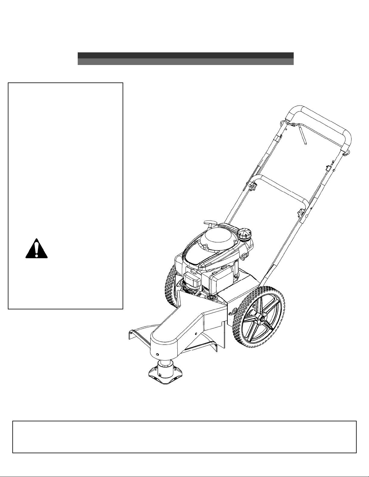
Make sure your trimmer is in safe working condition by kee ing the following guidelines in mind every time you
use your trimmer.
• Kee trimmer in good o erating condition and kee all guards and shields in lace. DO NOT o erate this
trimmer if any of the shields and guards are missing.
• Check all fasteners for secure fit to kee equi ment in safe working order. Make adjustments as necessary.
• To reduce fire hazards, kee engine free of grass, leaves or excessive grease.
• DO NOT o erate trimmer with a damaged or missing muffler. DO NOT tam er with exhaust system; this may
cause a fire hazard.
• DO NOT o erate engine if air cleaner or the cover over the carburetor air intake is missing. Removal of these
arts could create a fire hazard.
• Before cleaning, making adjustments or re airing the trimmer, STOP engine, disconnect s ark lug wire and
allow engine to cool.
• Handle gasoline with care. DO NOT smoke or use o en flame near gasoline. Use only a roved gasoline
containers. Never fuel or run trimmer in oorly ventilated areas, such as a garage or utility building.
• Always re lace fuel tank ca . Be sure to clean u any s illed gasoline.
• Do not change the engine governor settings or over-s eed the engine; severe injury or damage may result.
• Never store mower with gasoline in the tank inside a building where fumes may reach an o en flame or s ark.
Always allow engine to cool before storing.
Trimmer Maintenance
WARNIN
–
ALWAYS STOP EN INE AND DISCONNECT SPARK PLU
WIRE BEFORE PERFORMIN ANY ADJUSTMENTS OR SERVICE.
NEVER ADD ASOLINE TO A HOT EN INE – ALLOW EN INE TO
COOL BEFORE ADDIN ASOLINE.
Thumb wheel
Engine
• Refer to the engine service manual rovided with this unit.
Belts
• Occasionally check the belts for wear. A worn belt should be re laced.
Belt Adjustment
During the first few hours of o eration all belts go through a “break-in eriod” after which
th
e belts may need to be adjusted using the following instructions. Indications that the belts
need to be adjusted include:
• Loss of ower at the trimming head causing the head to s in unusually slow or sto .
• Excessive wear on belt due to sli ing.
• The belt that owers the transmission is designed to be under constant tension and
needs no further adjustment.
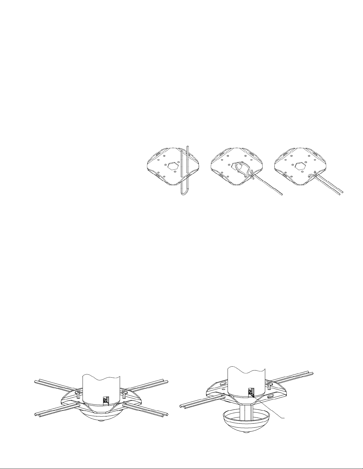
• The belts used to engage/disengage the trimmer head can be adjusted using the
following instructions:
1. Locate the thumb wheel adjuster on the control cable (see illustration).
2. Release control bail to disengage trimmer head.
3. Rotate thumb wheel a few turns counterclockwise (from normal o erating osition).
4. Re-engage trimmer head.
5. If trimmer head has not returned to normal o eration, re eat ste s 2-4.
Important!
Do not over tighten cable adjuster. This may cause the cable to break
.
Excessive force should NOT be required to fully engage control bail.

㝆
ɤ
9
Belt Replacement
Head Engagement Belt A Replacement
1. Remove front belt cover.
2. Loosen or remove fasteners used to attach engine to allow engine to shift. Slide or tilt engine so lower engine ulley I moves
away from transmission, creating a ga to allow belt to be removed.
3. Remove old belt.
4. Install new belt by first routing belt under the engine and around lower engine ulley I .
5. Then route belt between two idler ulleys as shown F .
6. Install belt around front ulley B .
7. Ensure that belt is correctly installed between the belt guides C and adjacent ulley.
8. Ensure that belt is correctly installed in the grove of each ulley.
9. Ensure that belt is over the to of the transmission axle E .
10. Tighten or reinstall fasteners used to attach engine.
11. If belt tension had reviously been adjusted, reset thumb wheel adjuster by rotating wheel clockwise as far as adjuster will allow
(see illustration in belt adjustment instructions). If head does not ro erly engage refer to belt adjustment instructions.
12. Reinstall front belt cover.
Transmission Power Belt H Replacement
1. Remove front belt cover.
2. Remove Head Engagement Belt A er instructions above.
3. Remove old belt.
4. Install new belt by first routing belt under the engine and around u er engine ulley J .
5. Then route belt around transmission ulley D .
6. Finally route belt around rear idler ulley G . The idler ulley is s ring loaded, making it difficult to finish belt installation. To
ease belt installation ush idler ulley toward transmission ulley while wra ing belt around idler ulley. CAUTION – Pinch
Hazard: Ensure that you do not get any art of your body between the belt and the ulleys as this may cause injury.
7. Reinstall Head Engagement Belt er instructions above.
8. Reinstall front belt cover.

㡆
ǝ
10
Assembly
When ordering re lacement arts
* USE PAINT CODE: TK=BLACK
Item # Part # Description Item # Part # Description
1 N/A Engine - Honda 16 NB275 Washer - AE Flat 5/16
2 NB170 Nut - errated Flange 5/16-18 17 NB180 Nut - Nyloc 1/4-20
3 NB253 Bolt - errated Flange, 5/16-18 X 1 1/4 18 19561 Grip - Handle, Anti-Vibration
4 19018 Pulley - Double Drive, Trimmer 19 19005 Bail - Trimmer
5 NB271 Washer - U Flat 3/8, ZY Carbn tl 20 19017* Handle - Top, P Trimmer
6 NB607 Washer - P Bellville 21 NB278 Bolt - 1/4-20 X 1 3/4
7 NB238N Bolt - HHC 3/8-24 X 1 22 NB587 Bolt - Carriage, 5/16-18 X 1 3/4
8 2019 Guard - Belt 23 10399* Handle - Lower
9 19135 Clip - Panel 24 NB596 Bolt - errated Flange, 5/16-18 X 3/4
10 9030 Key tock - 3/16 X 1 25 26X249 crew - .312-18 X .75
11 19027 Lever - Transmission Engagement 26 19016* Cover - Rear, P Trimmer
12 19823 Grip - TP Lever 27 19034 Belt - 60", Trimmer
13 19101 Cable - Transmission Control; TP 28 2006* Base - Lower Motor
14 19006 Cable - Control, Trimmer 29 19004 hield - Rubber
15 2030 Knob - Black Plastic 30 20883 pacer - Pulley

䍆
ɤ
Trimmer Head Assembly
11
When ordering re lacement arts
* USE PAINT CODE: TK=BLACK
!"
#$
#%&'()'*+&,-
$
#./
01&'(,-2*
3
#&&
04% !5"&'6
&
/3
06#37&8
(
#3
29&')3+,-
.
#&'
#
$
#/"
//
9:0*"
/
#&(/
#%'3/)'3*+&,-
/
*0;0*"
#$
<&'()'94%
$
//
+09:"
3
$.
2 0*
&
#/
06% '3/
(
#..
01"*=,-$'(
.
$
291"'8+$&>,-
/
0+0
/&/
$')'3#%
/
#/.
#%$'()'*+&,-
$/?
060 9"$'3
#&.
291"&'()'3,-+
$
#
0*"$'(+,-
3
/3
&
#/
064% !$'(,-@=+
(
#
06% &'(,-
.
/
06# !2"7&8$'8
#.
#%'3/)$'3+,-
#&/
#%&'()*+&,-
$/
#&3
01"'3/+&,-
$
($
#0299%0$'",(/
$
/3
+0
$$
()3
<7$)7.&

䑆
ǝ
ITEM # PART # DE CRIPTION
1 19015* Motor Base - Upper, TP Trimmer
2 10197 Bolt - Carriage 5/16-18X1 GR5 ZY
3 19019 Bearing - 1/2" Flange Mounted
4 10216 Bolt - Carriage 5/16-18X3/4 GR5 ZY
5 NB170 Nut - err Flange 5/16-18 ZY
6 NB604 Bolt - 3/8-16 X 1 GR5 ZY
7 21805 Bearing - ide Flange, 3/4" ID
8 NB182 Nut - Nyloc 3/8-16 ZY
9 NB107 Bolt - 3/8-16 X 1 1/2 HCC GR5 ZY
10 T30V Pulley - Idler Clutch, 2 3/4 OD
11 NB174 Nut - Jam 3/8-16 ZY Grade 2
12 19024* Idler Arm - Transmission
13 7821 Latch pring
14 NB272 Washer - AE Flat 3/8 ZY
15 NB280 Nut - 2 Way Lock 3/8-16 ZY
16 19020 Transmission - tring Trimmer
17 21808Z Axle - TP Trimmer, 3/4" ZP
18 26X249 crew - .312-18 x .75
19 19087* Guard - Chain; Trimmer
20 NB501 Bolt - 5/16-18 X 1 HCC GR5 ZY
21 NB579 Washer - Fender, 5/16 X 1 1/4 OD ZY
22 16823 Bushing - houlder 3/8, ZT60
23 19023* Bracket - Idler Arm, P Trimmer
24 19053 Belt - 24", P Trimmer
25 NB126 Pin - Cotter, 1/8 X 1
26 19036 Pin - Cotter, 3/16 X 2.25; ZP
27 21806 pacer - 1.25 OD X .75 ID X .375
28 21807 procket - No. 35, 60 Teeth, 3/4" Bore
29 19035 Pin - Cotter, 1/8 X 1-1/2; ZP
30 19021 procket - No. 35, 10 Teeth; 1/2" Bore
31 19044 Chain - AN I #35, 70 Link Loop
32 MWB Bearing - Wheel, 1 1/8"OD X 1/2"ID
33 19045*** Clutch - Wheel, 1.125 OD X 0.5 ID
34 19026** Wheel - 14", 1/2" Bearings; Trimmer
35 NB177 Washer - Mach 1/2 NR 14 GA
Drive Train Assembly
When ordering re lacement arts
* Use aint code: TK=Black
** Wheels include two bearings. Use art # MWB when re lacing bearings only.
Note: O tional wheel kits are available that include the bearings and wheel clutch
installed. Order art # 19085 for left wheel kit and art # 19086 for right wheel kit.
*** Wheel clutch must be installed in the correct orientation in order to o erate
ro erly. Wheel clutch is installed correctly when wheels s in freely while
trimmer is moving forward without the engine running (wheels will have resistance
when trimmer is moving backward). One of the wheel bearings may need to be
removed rior to installing the wheel clutch. The wheel clutch has an arrow on the
side to indicate the “free-wheel” direction. Ensure clutch is orientated so the free-
wheel direction corres onds to direction the wheel will rotate while trimmer is
moving forward and ress the clutch into the center of the wheel (interference fit).
Then re lace the wheel bearing and install the wheel on the axle.
Important! Rotate wheel in free wheel direction while mounting on axle
(spin and push at the same time). Ensure both wheel bearings remain fully
seated in wheel during wheel installation and operation. Failure to do so may
cause damage to wheel clutch.
12
Arrow on clutch
shows direction
wheel s ins freely
when installed.

但
ɤ
OWNER’S
MANUAL
Each trimmer has its own model number. Each engine has its
own model number. The model number for the trimmer will be
found on the left hand side of the motor base. The model
number for the engine will be found on the to of the blower
fan housing.
All trimmer arts listed herein may be ordered directly from
Swisher or your nearest Swisher dealer.
All engine arts may be ordered from the nearest dealer of the
engine su lied with your mower.
WHEN ORDERING PARTS, PLEASE HAVE THE
FOLLOWING INFORMATION AVAILABLE:
* PRODUCT – TRIMMER
* SERIAL NUMBER - _______________
* MODEL NUMBER - _______________
* ENGINE MODEL NUMBER - _______________
TYPE - _______________
* PART NUMBER WITH PAINT CODE
* PART DESCRIPTION
TELEPHONE - 1-800-222-8183
FAX - 1-660-747-8650
SWISHER ACQUISITION INC.
1602 CORPORATE DRIVE
WARRENSBURG, MO 64093
Visit us at: www.swisherinc.com
MODEL NO.
STP4422HO
Changing your landscape since 1945.
13

偆
ǝ
19129 REV 19-001
Self Propelled
Easy Glide
MANUAL DEL
PROPIETARIO
SWISHER ACQUISITION INC.
1602 CORPORATE DRIVE, WARRENSBURG MISSOURI 64093
TELÉFONO 660 747 8183 FAX 660 747 8650
Número del modelo
Ensamblaje
Funcionamiento
Servicio y ajuste
Piezas para
reparación
Visítenos en www.swisherinc.com
Del número de serie
L219 001001
STP4422HO
Lea y siga todas las
advertencias e instrucciones
sobre seguridad antes de
poner en funcionamiento
este equipo.
IMPORTANTE
Hecho en
EE.UU.
de Estados Unidos y partes mundial

孆
ɤ
1) Garantía del motor Todos los motores que se utilizan en nuestros roductos oseen una
garantía se arada que las extiende el fabricante a cada motor.
Cualquier roblema en el funcionamiento del motor es
res onsabilidad del fabricante del motor y de ninguna manera
Swisher o sus agentes son res onsables or la garantía del motor. El
teléfono de atención de Briggs & Stratton Engine Service Hot Line es
1-800-233-3723.
2) Uso Comercial Este roducto no ha sido diseñado ara uso comercial y no osee
garantía comercial.
3) Limitación Esta garantía se a lica sólo a los roductos que se han ensamblado,
ajustado y o erados correctamente de acuerdo con las instrucciones
contenidas en este manual. Esta garantía no se a lica a ningún
roducto de Swisher que ha sido objeto de modificaciones, mal uso,
abuso, ensamblaje o instalación incorrectos, daños en el embarque, o
a un desgaste normal del roducto.
4) Exclusiones Están excluidos de esta garantía el desgaste normal, los ajustes
normales y el mantenimiento normal.
En caso de que usted tenga un reclamo am arado or esta garantía, debe regresar el roducto a un
re resentante de servicio autorizado. Todos los cargos de trans orte, daños o érdida que se roduzcan
durante el trans orte de las iezas suministradas ara el cambio o re aración bajo esta garantía los
cubrirá el com rador. Si tiene reguntas relacionadas con esta garantía, or favor llámenos al número
gratis 1-800-222-8183. Antes de rocesar cualquier reclamo cubierto or la garantía, necesitamos saber
el número del modelo, el número del serial y el nombre del distribuidor Swisher autorizado en donde
usted com ró la odadora.
ESTA GARANTÍA NO SE APLICA A DAÑOS INCIDENTALES O CONSECUENCIALES Y
CUALQUIERA DE LAS GARANTÍAS IMPLÍCITAS SE LIMITAN AL MISMO PERIODO DE
TIEMPO ESTABLECIDO AQUÍ, PARA TODAS LAS GARANTÍAS EXPRESAS. Algunos estados
no ermiten la limitación de los daños consecuenciales o las limitaciones en la duración de una garantía
im lícita, así que las limitaciones o las exclusiones de arriba es osible que no a liquen ara usted. Esta
garantía le otorga derechos legales es ecíficos y usted uede tener otros derechos, los cuales varían de
un estado a otro. Esta es una garantía limitada de acuerdo a como se ha definido en la ley Magnuson-
Moss Act de 1975.
GARATA IITADA
La garantía que el fabricante otorga al com rador original es: Este roducto está libre de defectos en los
materiales y la mano de obra or un eriodo de dos (2) años desde la fecha de com ra or arte del
com rador consumidor original. Re araremos o cambiaremos, a nuestra discreción, las artes que se
determine estén defectuosas debido a los materiales o a la mano de obra. Esta garantía está sujeta a las
siguientes limitaciones y exclusiones:
2

蹀ԋ
• Lea, comprenda y siga todas las instrucciones del manual y sobre la orilladora antes
de encenderla
• Lea cuidadosamente este manual. Familiarícese con los controles y cómo operar
correctamente la unidad.
• ólo permita que los adultos responsables, que estén familiarizados con las
instrucciones operen la unidad.
•
Limpie el área de objetos tales como rocas, juguetes, etc., que pudieran ser arrojados
por la unidad.
• Asegúrese de que no haya otras personas antes de hacer recortes. Detenga la
unidad si alguien entra al área.
• Esté alerta sobre la dirección de la descarga de la orilladora y no la dirija hacia nadie.
• No dirija la descarga de la orilladora hacia objetos rompibles, tales como ventanas,
etc.
• No ponga en funcionamiento la orilladora sin que tenga colocadas todas las
protecciones y pantallas.
• Nunca deje la máquina funcionando sin supervisión.
• Pode sólo bajo la luz del día o con buena luz artificial.
• No opere la orilladora mientras esté bajo la influencia del alcohol o de drogas.
• Tenga cuidado con el tráfico cuando esté operando cerca de vías de comunicación.
• Use la orilladora de acuerdo a lo proyectado por el fabricante y como se describe en
el manual.
• No ponga a funcionar la orilladora si se ha caído o está dañada de alguna forma.
iempre haga que reparen los daños antes de ponerla a funcionar.
• iempre use gafas de seguridad o protectores para los ojos cuando use la orilladora.
• Vístase adecuadamente. No opera la orilladora cuando esté descalzo o cuando use
sandalias abiertas. Use sólo zapatos sólidos para una buena tracción cuando esté
rebajando. Use camisas manga larga o chaquetas, también use pantalones largos.
No pode usando pantalones cortos.
• Mantenga los ojos y la mente en su orilladora y en el área que está podando.
• No permita que otros intereses lo distraigan.
• No coloque las manos y los pies cerca o debajo de las piezas rotatorias.
• Antes de limpiarla inspeccione o repare la orilladora, pare el motor y desconecte el
cable de la bujía y manténgalo lejos de la bujía para evitar un arranque accidental.
• No opere la orilladora si vibra anormalmente. La vibración excesiva es una señal de
daño.
Pare el motor y revise cuidadosamente el daño y repárelo como sea necesario.
• No ponga a funcionar la orilladora sobre grama húmeda, donde no sea posible una
pisada firme. Camine, nunca corra.
• Detenga la orilladora cuando cruce sobre sendas de grava, etc.
3
Instrucciones sobre seguridad
Este símbolo de alerta de seguridad indica mensajes importantes en
este manual. Cuando vea este símbolo, lea cuidadosamente el mensaje
que sigue y esté alerta a la posibilidad de lesiones personales

김ԋ
4
Las pendientes son un factor principal relacionado
con
la p
érdida de
control y de accidentes por resbalones, los cuales pueden ocasionar
lesiones graves. Todas las pendientes exigen mayor precaución. Si se
siente incómodo en una pendiente no realice la poda.
Funcionamiento en pendiente
•
Í: Pode a través de la cara de una pendiente y no arriba y abajo
• Í: Quite los objetos tales como rocas, ramas de árboles, etc.
• Í: Esté pendiente de los agujeros, los surcos o los topes. El césped alto puede
esconder los obstáculos.
• NO: Pode cerca de declives, zanjas o terraplenes. El operador podría perder
apoyo o balance.
• NO: Pode en exceso las pendientes pronunciadas
• NO: Pode sobre el césped húmedo. La pisada sin apoyo podría ocasionar
resbalones.
Niños
•
Mantenga a los niños fuera del área y bajo la supervisión de otro adulto
responsable.
• Esté alerta y apague la máquina si los niños entran al área.
• Antes y cuando repase, observe hacia atrás y hacia abajo si hay niños.
• Nunca permita que los niños pongan a funcionar esta máquina.
• Tenga mayor cuidado cuando se aproxime a las esquinas ciegas, arbustos, árboles
o hacia otros objetos que puedan obstruir la visión.
• Tenga mucho cuidado cuando manipule gasolina y otros combustibles. on
inflamables y sus gases son explosivos.
• Use sólo un recipiente aprobado para el combustible.
• Nunca quite la tapa de la gasolina o añada combustible con el motor encendido.
• Permita que el motor se enfríe antes de agregarle más combustible. No fume.
• Nunca recargue de combustible la máquina en ambientes interiores.
• Nunca almacene la máquina o el recipiente de combustible donde haya una llama
abierta, tal como un calentador de agua.
• Nunca ponga a funcionar una máquina en un área cerrada.
• Mantenga las tuercas y los pernos roscados apretados y el equipo en buena
condición.
• Nunca interfiera los dispositivos de seguridad
• Mantenga la máquina libre de grama, hojas o de otras partículas. Limpie los
derrames de aceite y de combustible. Permita que la máquina se enfríe antes de
almacenarla.
• Detenga e inspeccione el equipo si golpea un objeto. Repárelo, si es necesario,
antes de volverlo a encender.
• Nunca haga reparaciones o ajustes con el motor encendido.
Servicio

김ԋ
5
Cuando está en funcionamiento, cualquier cortadora uede
chocar con objetos extraños que odrían ser lanzados a los ojos,
lo que odría causar lesiones graves. Siem re use lentes de
seguridad certificados o gafas de seguridad de visión am lia
sobre los anteojos, antes de fijar la vista en cualquier maquina
cortadora y mientras esté o erando tal máquina.
El funcionamiento de cualquier cortadora roduce ondas sonoras
que ueden dañar el oído humano. Se recomienda rotección ara
los oídos.
¡PRECAUCIÓN!
Pueden ocurrir accidentes trágicos si el o erador no está alerta a la
resencia de los niños. Los niños, a menudo, se sienten atraídos or
las máquinas y or la actividad de odar. Nunca asuma que los
niños se quedarán donde usted los vió anteriormente.
No o ere la orilladora si vibra anormalmente. La vibración excesiva
es una señal de daño. Pare el motor y revise con cuidado el daño y
re árelo como sea necesario.
Ajuste del mango
Ensamblaje
Las cajas contienen:
• Orilladora
Contenido de las iezas en bolsas:
• Manual
• Manual del motor
• Gafas de seguridad
• Botella de aceite de motor
• Línea cortadora
• llave hexagonal
Herramientas necesarias:
• Llave de 12,7 mm
Instalación de los mangos:
1. Quite los sujetadores sueltos de los mangos inferiores.
2.
Déle vuelta hacia arriba a los mangos y alinee el agujero
inferior de los mangos con el agujero del marco de la
orilladora. Instale los accesorios que se quitaron en el
aso anterior. Ajuste, ero no a riete los ernos
roscados.
3. Enganche la em uñadura su erior a la em uñadura
inferior con los botones y sujetadores incluidos con la
em uñadura inferior.
4. Ajuste los mangos ara que funcionen cómodamente.
5. A riete todos los ernos roscados.
Los mangos se ueden ajustar hacia arriba y hacia abajo y hacia
adentro y hacia fuera ara ro orcionar un funcionamiento
cómodo.
Etiqueta de advertencia
19991

獆
ɤ
6
¡Importante!
Use la longitud adecuada de la línea. El uso de una línea demasiado larga
ara la unidad, ocasionará atascamientos y mal funcionamiento.
Usan una cuerda de 45,7 cm
Com re la línea re cortada P3618
• Doble con holgura la línea cortadora a la mitad.
• Inserte la línea a través de los agujeros inferiores del disco (Paso 1).
• Llevar extremos alrededor ya través de la ranura en la brida de disco (Paso 2).
• Hale los extremos ara a retar el lazo (Paso 3).
Paso 1
Preparación de la unidad para uso por primera vez
• Llene el cárter del motor con aceite. Con esta unidad se ha suministrado un 20oz envase con
aceite. Una nueva unidad requiere 18-20oz. NO LO SOBRELLENE.
• Llene el tanque de combustible del motor con gasolina. LA GASOLINA DEBE
AGREGARSE EN EL EXTERIOR, EN UN ÁREA BIEN VENTILADA.
• Ins eccione ara estar seguro de que la cuerda se ha instalado correctamente. Para realizar una
instalación correcta, se ha ro orcionado un diagrama, y está exactamente arriba de el cabezal
de corte.
• Consulte el manual del fabricante del motor ara es ecificaciones de combustible y aceite.
Instalación de la línea recortadora
Paso 2 Paso 3
Posiciones del hilo de la bordeadora
Posiciones de ajuste del hilo de la bordeadora:
• La bordeadora cuenta con 4 untos de ajuste del hilo.
•Para segar con la bordeadora, se recomienda utilizar la configuración con 4 hilos ara
obtener un corte más arejo y uniforme.
• Para recortar vegetación larga o densa, se recomienda utilizar la configuración con 2 hilos,
ara un mejor rendimiento.
Para ajustar la altura del corte:
1. Afloje el tornillo de fijación con la llave de cabeza hexagonal incluida.
2. Deslice el cabezal de corte hacia arriba o abajo, hasta la altura de corte deseada.
3. A riete el tornillo de fijación.
4. Puede utilizarse cualquier altura de corte con cualquier configuración de hilos.
Tornillo
de fijación
Configuración con 2 hilos
Se ilustra ajustada a una altura de corte alta
Configuración con 4 hilos
Se ilustra ajustada a una altura de corte baja

瑆
ǝ
7
Consejos para podar
Solucion de problemas
•Si no se arranque el motor, quitar el filtro de aire para asegurarse que el
filtro y el carburador estan limpios.
• No levante la cabeza recortadora cuando esté odando. Deje que la cabeza descanse levemente,
tocando la tierra.
• Mantenga un ojo sobre la longitud de la línea recortadora. A medida que la línea se hace más corta
también se hace menos efectiva ara cortar y llevará más tiem o ara odar adecuadamente. Cambie
la línea cuando sea necesario. (Vea la instalación de la línea recortadora).
• No ode la grama húmeda.
• Tenga cuidado cuando recorte en endientes.
• Use la longitud a ro iada de la línea. El uso de una línea demasiado larga ara la unidad, ocasionará
atascamientos y mal funcionamiento.
Operación
Importante: Para garantizar la correcta o eración, lim ie el motor y la bordeadora eriódicamente.
Retire los restos acumulados en la arte su erior del motor. Durante la o eración, los residuos ueden
enroscarse en el cabezal de la bordeadora. El uso rolongado en este estado uede rovocar un desgaste
excesivo y daños en las iezas. A ague la bordeadora y retire los residuos eriódicamente.
Para arrancar la bordeadora:
1. Retire los residuos acumulados en el motor y el cabezal de la bordeadora.
2. Coloque el control del acelerador en la osición “FAST” (Rá ido).
3. Sujete firmemente la em uñadura de la soga y jale lentamente hasta sentir resistencia. Luego, jale
rá idamente con una brazada com leta.
4. Una vez que el motor arranque, deje el control del acelerador en la osición “FAST”. El control
del acelerador debe estar en la osición rá ida ara un máximo rendimiento.
5. Conecte el cabezal de corte.
6. Comience a recortar.
Para conectar/desconectar el cabezal de la bordeadora:
• Conexión: Jale el gancho de control hasta que haga contacto con la em uñadura su erior y sujételo
junto con la em uñadura. Si el cabezal de la bordeadora no se conecta com letamente, consulte la
sección de ajuste de la correa.
• Desconexión: Libere el gancho de control. El cabezal de la bordeadora debería detenerse en unos
segundos. De lo contrario, consulte la sección de ajuste de la correa.
Para activar/desactivar la transmisión:
• Activación: Jale la alanca de activación de la transmisión hasta que haga contacto con la
em uñadura su erior y sujétela junto con la em uñadura.
• Desactivación: Libera la alanca de activación de la transmisión.
Para detener la bordeadora:
1. Libere el gancho de control.
2. Coloque la alanca de control del acelerador en la osición “SLOW” (Lento) durante unos
segundos y, luego, colóquela en la osición “STOP” (Detención).
Importante: Para una o eración más segura, verifique que los residuos no salgan des edidos en
su dirección ni la de otras ersonas.
This manual suits for next models
1
Table of contents
Languages:
Other Swisher Trimmer manuals

Swisher
Swisher STGUARD22 User manual

Swisher
Swisher ST67522BS User manual

Swisher
Swisher STD67522BS User manual

Swisher
Swisher Trim-N-Mow Installation instructions

Swisher
Swisher L216-335001 User manual

Swisher
Swisher E4-S4000 Owner's manual

Swisher
Swisher E4-S3000 Owner's manual

Swisher
Swisher ST60022Q User manual

Swisher
Swisher E4-HT3000 Owner's/ Owner's manual

Swisher
Swisher STD67522BS User manual