swissmex Amazona 380 User manual

BN647-0718NA
R00
Impreso en México
EQUIPMENT MODEL
EQUIPOS DE FERTILIZACIÓN
MODEL / MODELO
647030, 647035
647001, 641001
OPERATOR’S MANUAL
MANUAL DE OPERADOR
Amazona 380, Amazona 600E
Amazona 600, Precision
fertilizer spreader / Pulpo
PREMIUM
647030
Amazona 600E
647001
Amazona 600
647035
Amazona 380
641001
Precision fertilizer spreader
/
Pulpo
This three-point fertilizer spreader makes it possible to
evenly distribute granulated fertilizer and increase soil
fertility. It can also be used for broadcast seeding.
- The precision fertilizer spreader can be used to apply
fertilizer at ground level.
Fertilizadora tripuntal, con ella podrá esparcir de manera
uniforme el fertilizante granulado para aumentar la
fertilidad el suelo, o bien sembrar semillas al voleo.
Con el pulpo podrá aplicar fertilizante al pie de la planta.

1
INTRODUCTION
1.
SAFETY INFORMATION
2.
In this section, we will discuss the most important points for ensuring your safety and the safety of others.
2.1 PROTECTIVE EQUIPMENT
- Protective gloves
- Safety glasses
- Closed footwear
- Ear plugs or ear muffs
- Overalls
- Mask
Thank you for purchasing a Swissmex fertilizer spreader. We guarantee that this product is of the highest quality and that it was developed
with cutting-edge technology according to all quality standards.
This product was carefully designed and manufactured for optimal performance, economy, and ease-of-use. It is important for any operator
of this product to go over all information contained in this manual, to follow the step-by-step instructions, and to have the manual on hand
for reference when needed.
This manual contains important safety information: Read this information carefully and be on
the lookout for any possible accidents. Keep all labeling on the equipment and replace labeling
if necessary.
It is essential to use the following protective equipment while operating the fertilizer spreader:
ÍNDICE
4.
6.
5.
7.
8.
9.
1.
2.
3.
Introduction……………....................1
Safety information………......1, 2
2.1 Protective equipment
2.2 Safety measures
General information…………............3, 4, 5
3.1 Nameplate
3.2. Main components
3.3 Technical information
3.4 Assembly
Operation…………..................................................5,6,7,8,9
4.1 Before starting your equipment
4.2 How to cut the PTO to the correct length.
4.3 Start-up procedure
Maintenance..............................................................10
5.1 Regular maintenance guide
5.2 Major maintenance
5.3 Maintenance schedule
Common problems and troubleshooting.................10
Replacement parts.....................................11,12,13,14,15,16,17,18
Storage...........................................................18
Warranty.........................................................................19

2
2.2 SAFETY MEASURES
Follow all instructions on the labels attached to your equipment
Prevent accidents that can be caused by poor understanding or by not following the security measures established in this manual.
WARNING
Never attempt to spread moist fertilizer or seeds, as spreading will be difficult, and the
equipment may become damaged.
Read this instruction manual carefully before using your equipment.
Serious accidents can occur if the equipment is used incorrectly or if it is used by an untrained person.
Do not change or modify this product; doing so can jeopardize your equipment and can compromise your safety as well as the safety of
others. You assume the risk for any changes or modifications performed, and these alterations will make the warranty invalid.
Do not allow children, the elderly, people with special abilities, or animals near the equipment while it is in use, being maintained, or even
when it is in storage.
Always keep the equipment in perfect running condition.
When transporting your equipment, make sure it is properly connected to the tractor that is towing it. Do not exceed 25 km/h (15 mph).
If your work requires you to travel on federal or state roads, follow all road rules.
Keep hands, feet, and loose clothing away from moving parts.
Make sure your equipment is on flat and firm ground when you disconnect it.
The operator must not be impaired by or under the influence of alcohol, drugs, or medications. This is very dangerous.
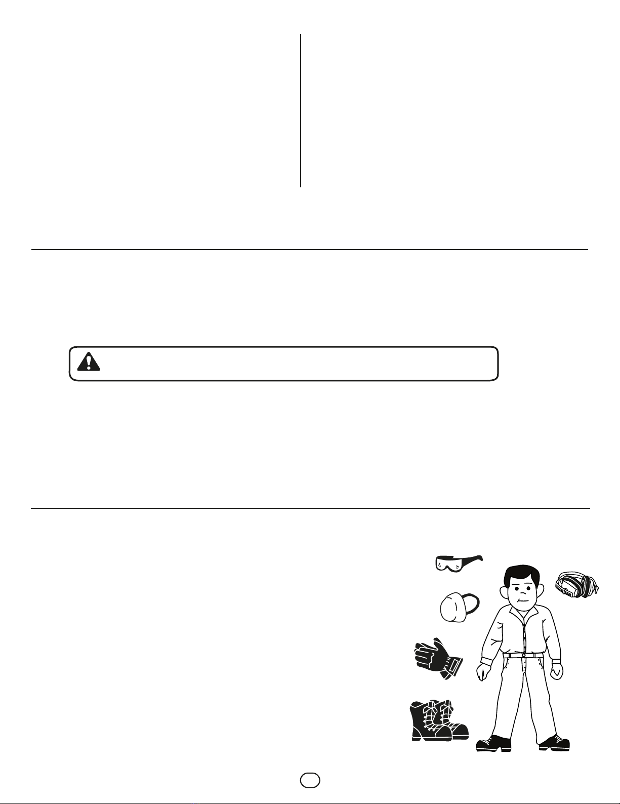
Always wear protective goggles to safeguard against errant materials.
Use all protective equipment recommended by the fertilizer’s manufacturer.
When spreading fertilizer or seed, no people should be near the fertilizer—only the person operating the tractor.
Never make modifications that affect the way the equipment functions or try to improvise repairs.
When performing maintenance, always disconnect the equipment from the tractor.
When traveling on roadways, place signals on the back of the equipment.
Never activate the PTO with the equipment on the ground; make sure the equipment is a minimum of 50cm (20in) from the ground.
If you are going to make a long trip with the fertilizer attached to the tractor, make sure the hopper is empty.
Clean the hopper after each use to prevent caking.
Never use the hopper if there are any liquid residues in the hopper.
Never use damp material in the hopper.

3
3.2 MAIN COMPONENTS
GENERAL INFORMATION
3.
In this section, we will discuss the product’s components.
3.1 NAMEPLATE
Calle Swissmex No. 500
Col.Las Ceibas
47440 Lagos de Moreno Jalisco
MODELO
No. DE SERIE
Your equipment has a nameplate that includes the model and serial number. This information
is necessary to file warranty claims and to obtain replacement parts. Record your
equipment’s information so you always have this information at hand.
8
4
5
2
9
10
3
6
1
7
1. Mechanical agitator
2. Chassis
3. Graduated dispenser
4. Exit hatch
5. Transmission
6. Distribution disc
7. PTO
8. Dispensing lever
9. Positioning lever
10. Hopper
(Depends on the model. The following description applies to model 647001)
13
2
1.- Mechanical agitator:
Makes the fertilizer flow
toward the exit hatches.
2.- Perforated plate:
Here you can adjust the
amount of fertilizer you
want to apply.
3.- Exit hatch:
You can configure various
distribution patterns by
moving the shield.

4
46
5
789
10 11
4.- Transmission:
Robust oil-immersed
transmission with steel
gears
5.-Distribution disc:
The blades ensure an
even and broad dispersal. 6.-Adjustable dispenser.
7.- PTO: Telescoping
three-lobe tube and
shaft guard.
8.- Dispensing control levers:
Used to control the application
amount. 9.- Positioning lever.
10.- Hopper:
Designed to promote
the flow of fertilizer to
the exit hatches.
11.- Chassis:
Laser-cut and mechanically
welded, coated in epoxy paint.
TECHNICAL INFORMATION3 3.
Because of our focus on technological advancement, we reserve the right to make changes or technical modifications to these products
without prior notice.
NOTA:
ESPECIFICATIONS DESCRIPTION
Item 647001 647030 647035 641001
Hopper capacity (lts) 600 600 380 600
Disc with blades Column Pins Movable parts Not included:
Agitator Mechanical Mechanical Mechanical Many included
Working width 14.0 meters. 14.0 meters. 14.0 meters. 5-7 adjustable.
stab grooves
Adjustable dispenser (lateral)
Adjustable dispenser
With 9 positions Not included Not included Not included
With 20 positions 5 positions 8 positions 5 positions
3-point tractor hitch Cat. II Cat. II Cat. I y II Cat. II
Approx. weight 161 kg (355 lbs)145 kg. (320 lbs) 80 kg. (176 lbs) 260 kg.
Sieve Not included Not included Not included
Not included Not included Not included
Upper and
lower
Outputs for furrows
Minimum power required 35 HP
5 double
ASSEMBLY34.
Make sure the equipment you have received is complete and the following items are included:
- Complete equipment with:
- Dispensing lever
- Chassis
- Agitator
- Disc with blades
- Hopper
- Gearbox
- Operator’s manual
- Parts brochure
- PTO
647001
AMAZONA 600
BN647030-1017NA
R06
Impreso en México
EQUIPOS DE
FERTILIZACIÓN
MODELO
647030, 647035
647001, 647050
MANUAL DE OPERADOR
Amazona 380, Amazona 600E
Amazona 600, Pulpo
PREMIUM
647030
Amazona600E
647001
Amazona600
647035
Amazona380
641001
Pulpo
Fertilizadora tripuntal, con ella podrá
esparcir de manera uniforme el
fertilizante granulado para aumentar la
fertilidad el suelo, o bien sembrar
semillas al voleo.
Con el pulpo aplicar fertilizante al pie de
la planta.

5
OPERATION:
4.
4.1
BEFORE STARTING YOUR EQUIPMENT
- Visually examine your fertilizer spreader to make sure that it is in good condition and complete, and that the nuts and bolts are in place and
tightened.
- Make sure the agitator is properly situated at the bottom of the hopper.
- Make sure that the dispensing levers can be manually lifted and lowered; if they cannot, lubricate the exit hatches at the bottom of the
hopper.
- Verify that the dispensing disc rotates freely. This is checked manually.
4.3 3 START-UP PROCEDURE
1. Attach your equipment to the tractor’s 3-point hitch.
2. Align the hopper in two planes, using the first and second hitch point on the tractor for one plane and the third point for the other plane. The
hopper should be leveled so that the ground and the bottom of the blades are 70cm apart.
3. Connect the PTO and make sure that the PTO is adequately sized for you to raise and lower the equipment. If it is not the proper size, cut
the telescoping tubes and protective shielding so that you can raise and lower the equipment freely. (Remember that the overlap must be 1/3
of the tube.)
4.2 CUTTING THE CARDAN SHAFT TO THE CORRECT SIZE
- Separate the cardan shaft into two parts.
- Mount half the shaft onto the tractor and the other half of the shaft onto the implement.
- Connect the fertilizer spreader to the tractor 3-point hitch.
- Align the implement so that the two half shafts are at the same height.
- Place one half-cardan shaft next to the other half-cardan shaft.
- Measure 40mm from the start of the plastic shielding tube.
- Cut the plastic shielding (cut the same length for both half shafts).
- Cut the male and female shafts the same length that the protective shielding was cut.
- Round off the cutting edges and clean up the filings carefully.
- Grease the PTO driveline shaft and the plastic shielding
1/3
Ideal overlap
MINIMUM
2/3
Ideal overlap
COUPLING JOB LENGTH APPROX. 2/3 Lu2/3
NOTA:
Identify which side goes to the tractor and which side goes to the equipment (according to the
label on the PTO). Remember that the female tube of the cardan shaft always goes to the tractor.
40 M M

6
UREA Ki l ograms/ Hectare
Km/h
LEVER
POSITION
LEVER
POSITION
LEVER
POSITION
1
2
3
4
5
4
182
555
931
1211
6
122
370
621
807
8
91
277
465
605
10 12 14 16
73 61 51 45
222 185 155 137
372 310 260 229
484 404 338 299
BARLEY
Km/h
1
2
3
4
5
4
113
383
658
865
6
75
25
439
577
8
56
191
452
594
10 12 14 16
45 38 32 28
153 128 107 94
263 219 184 162
346 288 242 213
WHEAT
Km/h
1
2
3
4
5
4
181
558
962
1241
6
121
372
641
828
8
90
279
480
620
10 12 14 16
72 60 51 45
223 186 156 138
384 321 269 237
496 414 347 306
NOTE:
Each model has its own spreading table,
which is affixed to the hopper.
4. Place fertilizer or seed in the hopper.
5. When starting the machine, the bottom of the blades should be 70cm from the ground for an even distribution, and the tractor RPM should be
at 540.
6. Select the working speed and adjust the hatch openings as specified in the table according to the
amount of product you wish to spread per hectare. (The products whose spreading information is not presented in the tables rely on your
knowledge and experience.)
7. When you begin spreading, always move the tractor at an even speed to ensure an even distribution.
8. Remember that when you go faster, less product is spread per hectare, and vice versa.
9. Engage the PTO at a low rpm and gradually increase the tractor engine rpm to 540.
START-UP (641001)
1. Fertilizer must pass through the sieve to ensure that the fertilizer will flow through the barrel and tubes.
2. Open the fertilizer output using the control wire.
3. Open the boom and adjust the "Y" outputs appropriately, adjusting the dispersal pattern according to the furrow type.
4. Accelerate the tractor engine to 540 RPM on the PTO.
5. Set the tractor speed, and the fertilizer spreader will begin depositing fertilizer at ground level.
Ki l ograms/Hectare Ki l ograms/ Hectare

7
4. Place fertilizer or seed in the hopper.
5. When starting the machine, the bottom of the blades should be 70cm from the ground for an even distribution, and the tractor RPM should be
at 540.
6. Select the working speed and adjust the hatch openings as specified in the table according to the
amount of product you wish to spread per hectare. (The products whose spreading information is not presented in the tables rely on your
knowledge and experience.)
7. When you begin spreading, always move the tractor at an even speed to ensure an even distribution.
8. Remember that when you go faster, less product is spread per hectare, and vice versa.
9. Engage the PTO at a low rpm and gradually increase the tractor engine rpm to 540.
MIXTURE OF THOMAS
PHOSPHATE POWDER
AND POTASSIUM
THOMAS PHOSPHATE
POWDERS
AMMONIUM
SULFATE CRYSTALS
CALCIUM
CYNAMIDE
PELLETS
AMMONIUM
NITRATE
GRANULATED
SUPER POTASSIUM
HUMATE
FERTILIZER TYPE WORKING
WIDTH
RPM
SPEED
ORIENTATION
POSITION
SPREAD DENSITY PER HECTARE
Position of the exit hatch control levers
Vertical metal sheet reference number
GRANULAR
PHOSPHOROUS-POTASSIUM
BINARY FERILIZERS
(15-20 or 16-20 types)
GRANULAR COMPLETE
FERTILIZER
(with phosphorus, nitrogen,
and potassium)
UREA
Kg/hectare Kg/hectare Kg/hectare Kg/hectare Kg/hectare Kg/hectare Kg/hectare Kg/hectare Kg/hectare
FEED
RATE
SPREAD TABLE FOR AMAZONA 600 FERILIZER SPREADERS
ALL DATA IS INFORMATIVE PURPOSES ONLY. SWISSMEX ASSUMES NO LIABILITY FOR THE USE OF THIS INFORMATION.

8
SPREAD TABLE FOR AMAZONA 600 FERTILIZER SPREADERS
SPREAD DENSITY PER HECTARE
ALL DATA IS FOR INFORMATIVE PURPOSES ONLY SIWSSMEX ASSUMIES NO LIABLILITYFOR THE USE OF THIS INFORMATION.
Position of the exit hatch control levers
Vertical metal sheet refernce number
RYE
CEREAL
TYPE RPM
SPEED
ORIENTATION
POSITION
FEED RATE
WORKING
WIDTH
BARLEY
OATS
WHEAT
RAPESEED
Kg/hectareKg/hectareKg/hectareKg/hectare
SPREAD TABLE FOR AMAZONA 600 FERTILIZER SPREADERS
ALL DATA IS FOR INFORMATIVE PURPOSES ONLY SIWSSMEX ASSUMIES NO LIABLILITYFOR THE USE OF THIS INFORMATION.
SPREAD DENSITY PER HECTARE
Position of the exit hatch control levers
Reference numbers on the vertical control levers
RPM
SPEED
ORIENTATION
POSITION
FEED RATE
WORKING
WIDTH
FERTILIZER
TYPE
COARSE GRANULAR
FERTILIZER,
2.0 TO 4.0 mm
FINE GRANULAR
FERILIZER,
0.15 to 2.0 mm
CRYSTALLINE
FERTILIZER
DAMP POWDERED
FERTILIZERS
Kg/hectareKg/hectareKg/hectareKg/hectare

9
This product is easy to maintain. If you follow the steps in this manual, your product will have a very long service life.
MAINTENANCE:
5.
5.2 MAJOR MAINTENANCE
Major repairs, especially transmission work, must be performed by a qualified mechanic.
5.1 DAILY MAINTENANCE GUIDE
- Never leave material—especially fertilizers—in the hopper overnight, as humidity may solidify fertilizers and damage the fertilizer spreader.
- Each year, make sure the transmission oil level is correct. If necessary, refill up to the inspection cap. Use 30w40 oil.
- After each workday, grease all moving parts (hatches, levers, cardan shaft).
5.3 AINTENANCE SCHEDULE
FREQUENCY TASK
Daily
At each change of season
Empty the hopper after each use.
Grease the cardan shaft.
Check the transmission oil level.
Lubricate the hatch runners.
COMMON PROBLEMS AND TROUBLESHOOTING
6.
PROBLEM CAUSE SOLUTION
The fertilizer spreader does
not distribute material at the
distance indicated on its
label.
Fertilizer falls too closely to
the fertilizer spreader
The dispensing disc does not
turn.
The fertilizer falls more
heavily on one side.
There is no output, even
though the hopper is full of
fertilizer.
The tractor PTO is not at 540
rpm.
The fertilizer spreader is tilted
backwards
The shear bolt is broken
One hatch door is opened
wider than the other.
The fertilizer is damp
Increase the tractor PTO to
540.
Make the third hitch point level so
the fertilizer is parallel to the
ground
Replace the shear bolt.
Open both hatches equally.
Replace the damp fertilizer with
dry fertilizer.
: It is best to store your equipment in the shade
NOTE:

10
647001
Amazona 600
complete gearbox
45
23
47
57
51
49
46
48
48
*
56
45
50
52
GEARBOX
Part No. Code Qty
Description Part No. Code Qty
Description
ASpare parts and consumables always available.
46 152-146NC 3/8” Nut
48 768-089NC 3/8” Flat washer
49 768-075NC 3/8” Lockwasher
BMedium-use parts, available at discretion
23
45
47
51
52
53
54
56
57
120-046 5/16” Hex nut
768-118NC 5/16 X 2 ½” Hex screw
647-103NC 3/8 X 5” Hex screw
647-068NC 3/8 X 1 3/4” Spiral bolt
647-033 Disc couplin
768-071NC 3/8 X 3/4” Hex screw
647-032 Disck with blades
647-150 Complete mechanical agitator
208021004 Gearbox
*
*
This product is only sold as a complete unit.
54
53
49
DOSIFICADOR
Part No. Code QtyDescription
B
8
25
25G
35
42
43
501-015 Lever handle
647-040 Dispenser
647-040-C1 Complete dispenser
614-063NC 1/4 X 1 1/4” Spiral bolt
647-024 Exit hatch B”
647-023 Exit hatch “A”
25
34
8
32
42
43
35
25G
SPARE PARTS
7.
Medium-use parts, available at discretion.

11
Part No. Code QtyDescription
24
24a
CHASSIS AND HOPPER
2
9
16
15
14
20
1
17
17a
23
60 12
13
59
11
11 4
3
12
1
BMedium-use parts, available at discretion.
2
3
4
9
11
14
15
16
647-017 600 liter hopper
647-133 Fixin plaque gasket
647-003 Hopper fixing plaque
647-034 Spreader cup fastener
501-050 1/8” “R” pin
647-071NC 5/8 X 1 3/4” Flat washer
647-041NC 5/8” Lockwasher
647-073NC 5/8” Hex nut
Drive shaft (La Magdalena PTO)
Drive shaft (Turkish PTO)
1 1/4” Row lock
5/16” Hex nut
La Magdalena drive shaft
Turkish drive shaft
3rd Point hitch pin
5/16” Lockwasher
647-136
647-172
647-137NC
120-046
1002/640/KH/
9.1-22.L30.8
KT2.101.330.064
768-200
501-127
17
17a
20
23
24
24a
59
60

12
FERTILIZER SPREADERS
647035
Amazona 380
20
22
22a 21
40
42
12G 41
10
13
16
19
16
18
16
17
18
17
16
18
17
9
10
1G
2G
16
17
18
23
43
43
18
32
42
42
26G
26G
32
31
30
32
L
24
23
25
42
18
42
42
30
32
31
32
31
30
32
Medium-use parts, available at discretion.
Spare parts and consumables always available.
16
17
18
36
768-089NC
768-075NC
152-146NC
803-067
3/8” Flat washer
3/8” Lock washer
3/8” Hex nut
Spring
No. Parte Código Cantidad
Descripción
A
16
8
12
2
1G
2G
9
10
12G
13
19
20
21
22
22a
23
24
25
26G
30
31
32
40
41
42
43
647-295-C
647-987-C
647-293
614-064NC
647-160-C
208021005
647-103NC
768-200
501-050
2002/800/KH/19.1-19.1
KT1.101.101.080
647-985
647-263
647-260
080-047-C
768-077NC
768-073NC
768-297NC
501-127
120-046
080-048
647-143
Complete mechanical agitator
Base with complete agitator
Felt ring
5/16X1 ½” Coiled spring pin
Disc with movable blades
Gearbox
3/8 x 5” Hex screw
3rd point hitch pin
“R” 1/8” pin
La Magdalena drive shaft
Tirkish drive shaft
5/16 x 1” Hex bolt w/washer
1/4” Hex nut
1/4” Lock washer
1/4” Flat washer
5/16” Lock washer
5/16” Hex nutl
5/16” Flat washer
No. Parte Código CantidadDescripción
B
1
1
1
2
1
1
4
1
1
1
1
2
1
1
8
4
4
4
8
12
16
2

13
6
7
40
12 14
1G
13
23
22
22
21
12
32
3
3
26
28
29
26
20
23
3
12
3
3
28
29
26
28
26
28
29
26
26
29
17
17a
10
7
16
14
12
14
13
18
12
13
14
19
19
14
13
12
14
14
15
647030
Amazona 600E
A
12
13
14
15
152-146NC
768-075NC
768-089NC
647-900
Hex nut 3/8”
Lockwasher 3/8”
Flat washer 3/8”
Disc with fixed blades
13
9
18
1
1G
3
6
7
20
23
26
28
29
32
40
10
16
17
17a
18
19
21
22
647-112-C
080-048
647-202
614-064NC
647-263
647-273
768-297NC
768-073NC
768-077NC
614-257
647-293
208021005
647-103NC
2002/800/KH/19.1-19.1
KT1.101.101.080
768-200
501-050
647-260
647-143
Complete mechanical agitator
5/16” flat washer
Agitator base
5/16 x 1 ½” Colled spring pin
Left hatch
Hatch opening bar
1/4” Flat wahser
1/4” Lockwasher
1/4” Hex nut
Knob
Felt ring
Gear box
3/8 x 5” Hex screw
La Magdalena drive shaft
Tukish drive shaft
3rd point hitch pin
“R” 1/8” pin
B
1
12
1
2
1
2
10
6
6
1
1
1
4
1
1
1
2
1
2
Part No. Code QtyDescription
Medium-use parts, available at discretion.
Part No. Code Qty
Description
Spare parts and consumables always available.

14
Complete mechanical agitator
5/16” flat washer
Agitator base
5/16 x 1 ½” Colled spring pin
Left hatch
Hatch opening bar
1/4” Flat wahser
1/4” Lockwasher
1/4” Hex nut
Knob
Felt ring
Gear box
3/8 x 5” Hex screw
La Magdalena drive shaft
Tukish drive shaft
3rd point hitch pin
“R” 1/8” pin
21G
43
24
25
26
27
23
HOPPER
66
66a
64
63
62
45G
44
60
54
45
54
46
4847
49
50
58
51
52
54
55
56
5750
53
10
11
12
65
25
68
67
26
25
69
70
641001
Precision Fertilizer Spreader

15
HOPPER
Note: Because of its commnitent to thecnological advacement, the company reserves the
right to make technial changes without prior notice
47 2-3 8X7X50 Shim
53 2-2 8X7X36 Shim
56 02-38 25X35X0.11 Washer
Part No. Code Qty.
Description
Part No. Code Qty.
Description
ASpare parts and consumables always available.
641001
Precision Fertilizer Spreader
1
1
1
10 614-043 Plastic bushing
11 614-040 Output plug
12 326-002 1/4X1/2” Round head screw
21G 614-065-C Complete cable
23 818-557NC M6 Hex nut
24 614-006 Concentric disc
25 501-050 “R” 1/8” pin
26 647-071NC 5/8 X 1 3/4” Flat wahser
27 614-042 Spinner bushing
43 614-063NC 1/4 x 1 1/4” Colled spring pin
44 647-111 1/2” Gear box
45G 647-110-C1 Complete gearbox
45 647-110 1/2” Gear box
46 647-097NC 47X25X7 output shaft
48 647-092 Output shaft
49 02-11 Large gear
50 02-18NC 1” Esternal pin
51 647-095NC 35X47X7 Output shaft
52 647-091 Input shaft
54 120-046 5/16” Hex nut
55 02-20NC 6205 Bearing
57 02-12 Small gear
58 647-063NC 5/16X2” allen screw
60 647-118 Gaskets for gearbox
62 647-003 Hopper fixing plaque
63 647-137NC 1 1/4” plaque
64 647-136 Drive shaft (La Magdalena PTO)
65 768-200 3rd point hitch pin
66 1002/640/KH/19.1-22.L30.8L La Magdalena drive shaft
.
66a KT2.101.330.064 Turkish drive shaft
67 647-041NC 5/8” Lokwasher
68 647-073NC 5/8” Hex nut
69 647-133 Fixing plaque gasket
70 647-034 Spreader cup fastener
BMedium-use parts, available at discretion
1
1
2
1
2
1
9
11
1
3
1
1
1
1
1
1
3
1
1
8
4
1
8
1
2
1
1
1
1
1
4
4
2
4

16
Part No. Code Qty.
Description
Medium-use parts, available at discretion
Part No. Code Qty.
Description
Medium-use parts, available at discretion
8
10
11
12
13
14
3
4
BOOM FRAME
AND CENTRAL JIB
BARREL
29
30G
31
32
13
30
26
26
26
26
33G
COMPLETE
BOOM SET
13
26
29
30
30G
31
32
33G
768-944
647-071NC
614-068
614-269
614-269-C1
614-209
614-257
614-214-C
Abrazadera SX 40/60
Rondana plana 5/8 X 1 3/4”
Manguera aire pesado 2”
(2.35 mts)
Salida “Y” p/aguilón central
c/sujetador
Sujetador grande
Perilla
Aguilones completos
B
3 614-064NC 5/16 x 1 ½” Spirol bolt
4 614-025 Worm shaft
8 0922.12.59.00NC 6208 bearing
10 614-043 Plastic bushing
11 614-040 Output plug
12 326-002 1/4X1/2” Round head screw
13 768-944 SX 40/60 Clamp
14 614-069 2” (2.85 mts) Heavy-duty air tube
B
641001
Pulpo
3
11
3
3
3
3
3
1
1
1
1
2
2
4
5
2

17
Because of our focus on technological
advancement, we reserve the right to
make changes or technical modifications
to these products without prior notice.
CENTRAL BOOM AND 1st SECTION
STABILIZER ARMS FOR TUBE HOLDERS (no inclluído en equipo)
OPTIONAL 5-OUTPUT
TO 7-OUTPUT
CONVERTER KIT
STORAGE
8.
Make sure to clean your equipment after each workday.
42
41G
70G
35
35
36
37
38
36
32
40
39G
14
13
NOTE:
B
B
641001
Precision Fertilizer Spreader
2
2
2
4
4
2
2
2
2
Part No. Code Qty.
Description
Medium-use parts, available at discretion
Part No. Code Qty.
Description
Medium-use parts, available at discretion
768-944
614-069
614-257
768-167NC
768-083
768-034
614-232-C1
614-208
13
14
32
35
36
37
38
39G
40
SX 40/60 Fastener
(2.85 meter) Heavy- duty air tube
Knob
1/4 x 2” Coiled spring pin
Washer for rotating center
Spring hinge
“Y” output for 1st section with fastener
Smart fastener
2
2
614-274-C
614-070
614-101-C
41G
42
70G
5 to output extension
2” (3.25 meter) Heavy-duty air tube
Cultivator attachment kit

18
WARRANTY:
9.
Contáctanos:
www.swissmex.com
Calle Swissmex No. 500
Lagos de Moreno Jal. México
Tels: 52 (474) 741 2200 / 741 2216
To validate your warranty, you must adhere to the Warranty Policy described below:
SWISSMEX RAPID SA DE CV will honor the warranty free of charge when any parts or components are found to have manu-
facturing or assembly defects after conclusive analysis at the manufacturing plant (Lagos de Moreno, Jalisco). Once the
damages have been verified and evaluated, the warranty will cover replacement parts or equipment for the damaged parts or
equipment. The warranty does not cover labor or transportation.
Your product warranty may be PREMIUM, MEDIUM, or BASIC, depending on the category of your equipment. The category is
specified on the cover of the product manual. You may also verify the product category on the website or by using a product
catalog.
WARRANTY PERIOD
Premium = 12 months
Medium = 6 months
Basic = 3 months
The warranty does not apply when:
• The cause of damage cannot be attributed to manufacturing defects or defective materials.
• Improper use of the equipment, or usage for which the equipment was not designed, and which is not recommended by the
user manual and its standards.
• Damage caused by natural disasters (earthquakes, floods, fires, lightning, and storms).
• When the equipment has suffered accidental or intentional blows, or when it has been exposed to harmful elements, includ
ing water, fire, inclement weather, etc.
• The customer assumes responsibility for damages that occur during transportation.
• If the serial number has been defaced or removed.
• If you use parts other than original Swissmex parts, in the case of commercialized products.
• Improper maintenance or maintenance performed by individuals who have not been authorized by Swissmex.
• If the original product design has been modified or altered.
• In cases of misuse, negligence, accidents, or when the rotary cutter is connected to a tractor with a power rating different
from what is specified on the technical sheet.
• Incomplete warranty form.
The Swissmex company covers damages sustained during transport for OCIMA-certified equipment.
Swissmex is not responsible for accidents or fatal injuries related to the equipment, nor is it responsible for theft.
The warranty does not cover:
• Consumables and normal wear and tear.
• Electrical parts.
• General replacement parts.
• The costs and fees related to shipping, transportation, and delivery services.
Product warranties must be handled by the product vendor or by the end user via e-mail: [email protected].
For products imported and marketed by Swissmex Rapid SA DE CV, the warranty period is established by the equipment
manufacturer.
Check your product manual to determine the warranty period for your product.
THE CUSTOMER MUST FILL OUT THE PRODUCT WARRANTY FORM AT THE TIME OF SALE
• Customer/user name:
• Model:
• Series number:
• Date equipment was purchased:
• Where it was purchased:
Customer’s seal and signature
IF THE PURCHASER DOES NOT COMPLETE THIS FORM THE PRODUCT WARRANTY IS NOT VALID.

19
INTRODUCCIÓN
1.
INFORMACIÓN DE SEGURIDAD
2.
A continuación describiremos los puntos más importantes a revisar para la seguridad de usted y de terceros.
2.1 EQUIPO DE PROTECCIÓN
- Guantes protectores
- Lentes de seguridad
- Zapatos cerrados
- Tapones auditivos o conchas
- Overol
- Mascarilla
Gracias por comprar una fertilizadora Swissmex, le garantizamos que el producto que ha adquirido cuenta con calidad insuperable ya que
fue desarrollado con tecnología de punta, siguiendo los estándares de calidad requeridos.
Este equipo fue cuidadosamente diseñado y fabricado con el fin de proporcionar el máximo rendimiento, economía y facilidad de
operación. Es importante que el operador conozca toda la información contenida en este manual, léalo antes de operarlo, siga las
recomendaciones paso a paso y téngalo a la mano para consultarlo cuando sea necesario.
Este manual contiene importantes advertencias de seguridad: lea con atención y esté atento a
cualquier posible accidente. Conserve todas las etiquetas del equipo y si es necesario
reemplácelas.
Al usar las fertilizadoras, usted deberá portar:
ÍNDICE
4.
6.
5.
7.
8.
9.
4.2 Cómo cortar el eje cardán al largo correcto
4.3
Procedimiento de arranque puesta en marcha
Mantenimiento..............................................................10
5.1 Guía para mantenimiento diario
5.2 Mantenimiento mayor
5.3 Calendario para mantenimiento
Posibles problemas, causas y soluciones.................10
Refacciones...........................................11,12,13,14,15,16,17,18
Almacenamiento...........................................................18
Garantía.........................................................................19
1.
2.
3.
Introducción……………....................1
Información de seguridad………......1, 2
2.1 Equipo de protección
2.2 Medidas de seguridad
Información general…………............3, 4, 5
3.1 Placa de identificación
3.2 Componentes principales
3.3 Datos técnicos
3.4 Ensamble
Operación…………..................................................5,6,7,8,9
4.1 Que debe hacer antes de poner en marcha su equipo
This manual suits for next models
6
Table of contents
Languages:
Popular Spreader manuals by other brands

BAUMAN
BAUMAN 440E Operator's manual

SnowEx
SnowEx VX-3200 owner's manual

Millcreek
Millcreek 97 Operator's manual

Glasdon
Glasdon ICEMASTER 50 Instruction leaflet

Douglas Dynamics
Douglas Dynamics SnowEx V-Pro SP-2000 installation instructions

SnowEx
SnowEx Super Maxx SP-9300XH Owner's manual and installation instructions

Boss Snowplow
Boss Snowplow TGS 300 owner's manual

Meyer's
Meyer's VB280 INSTRUCTION AND PARTS BOOK

DÖNDER
DÖNDER CGSA Series user manual

Boss Snowplow
Boss Snowplow MSC22875B owner's manual

Trynex International
Trynex International TurfEx RS7200E owner's manual

Millcreek
Millcreek 25G Series Operator's manual