SWIT FLOW2000 Series User manual

SWIT Electronics Co., Ltd.
Ver:A
User Manual
Please read this user manual
throughout before using

Preface
1. All internal technologies of this product are protected, including device, software and trademark.
Reproduction in whole or in part without written permission is prohibited.
2. All brands and trademarks of SWIT Electronics Co., Ltd. are protected and other relative trademarks in this
user manual are the property of their respective owners.
3. Due to constant effort of product development, SWIT reserves the right to make changes and improvements
to the product described in this manual without prior notice.
4. The warranty period of this product is two years, and does not cover the following:
(1) Physical damage to the products
(2) Any damage or breakdown caused by use, maintenance, or storage not according to the user manual’s
introductions.
(3) The attenuation of signal quality resulting from being used in any special environments.
(4) Any damage caused by not powering the product by package supplied power adaptor.
(5) Any damage or breakdown not caused by the product’s design, workmanship, manufacturing, quality, or
unauthorized repairs or parts replacement or other operations.
5. For any suggestions and requirements on this products, please contact us through
SWITElectronicsCo.,Ltd.
Address: 10 Heng Tong Road, Xin'gang Economic and Technological Development Zone,
Nanjing 210038 China
Phone: +86-25-85805753
Fax: +86-25-85805296
Email: contact@swit.cc
Website: http//www.swit.cc

Safety Precautions
Please follow the safety precautions before using. The following conditions are not covered by warranty.
1. Unauthorized repairs or other Unauthorized operations.
2. Inappropriate placement including but not limited to lighting, fire, exposure to rain, water or gas.
3. Using the wrong power supply.
Warning
Do not get any liquid inside the products
Do not block the ventilation openings or put substances inside, in order to avoid short circuit, fire or electric
shock.
Do not place the product in the rain or moisture to avoid electric shock or fire.
Danger
Switch the power off before connecting other devices.
Power socket: Make sure the power socket under the voltage range of the product to avoid short circuit,
electric shock and fire.
Power cable: Make sure the power cable is not pressed or tightened by any items or weights.
Power Load: Do not exceed the load on the wall outlet, extension cable or other porous receptacle to
avoid fire or electric shock.
Lightning: Disconnect the power cable if it is lightning or not using in a long period of time.
Working Environment
Please don't lay the product on any unstable place to avoid fallen damage.
Please don’t use the product in a place overheating, undercooling or with lots of moisture, or near by
strong magnetic devices.
Please don’t lay the product on metal shelf, in order to ensure the effective wireless transmission.
Packing list
This wireless system includes below accessories:
1. Transmitter 2.Receiver 3.Antenna*6 4.D-tap to lockable pole cable (0.6m)
5. Power adaptor 6.User manual 7.Warranty card 8. Articulating arm trestle

1.ProductIntroduction
FLOW2000 includes transmitter and receiver, adopts the latest encrypted transmission technology, and
supports SDI and HDMI wirelessly transmitted in 600 meters scale (Line-of-Sight), 2 channels SDI/HDMI digital
video transmission, auto pairing and OLED display. FLOW2000 is equipped with DC power connector, compact
size, portable, and the receiving signal is very stable.
2. Features
◆ HD/SD-SDI and HDMI transmission
Support up to 1080p 50/60Hz SDI & HDMI wireless transmission.
600 meters transmission distance
In open outdoor area, the effective transmission distance is approx. 600 meters (line of sight).
Wireless frequency
Pairing mode
Support auto pairing connection and manual switching of frequency points. Support one transmitter to
multi-receiver mode.
OLED Display
Display the current working parameter, such as signal format, wireless channel, signal strength, and so on.
Encryption
Support AES 128-bit encryption to protect the transmission.
All-Metal Shell
Both the transmitter and receiver adopt metal shell which is durable and solid.
All hardware design
The wireless system is hardware and plug-and-play designed, without installing software, easy to set up.
The system adopts 5180~5220MHz and 5760~5820MHz wireless frequency band(FLOW2000 Tx).
Channel Frequency
(MHz) Channel Frequency
(MHz)
00 5180MHz 04
01 5200MHz 05 5800MHz
02 5220MHz 06 5820MHz
03 5760MHz / /
5780MHz
Remark:
1. The transmission distance may be different, and depend on surroundings, radio wave conditions, buildings,
etc., the 600 meters transmission distance may be not guaranteed.
2. The wireless transmission might be interrupted if there’re many other devices of 5GHz wireless bandwidth
Used in the same location.
3. Signal reception may be affected by the position, height and angle of devices. If reception video is not stable,
please physically adjust placement for the optimized signal.
4. Set the antennas straight up and set receiver higher to enhance the transmission efficiency.
5. The product offers theAES 128-bit encryption to protect the wireless transmission. Please still be
aware of the intentional signal interception from third person. Do not use it for important communication.
The system adopts 5182.5~5222.5MHz and 5762.5~5822.5MHz wireless frequency band(FLOW2000 Rx ).

3.AppearanceInstruction
Transmitter FLOW2000
⑴Antenna
⑵Product label
⑶Link:Wireless status indicator
⑷Video:Video signal indicator
⑸Power:Power status indicator
⑹OLED:0.96-inch OLED
⑺Five-direction switch:Five-direction adjustment button (adjust the display menu to switch and confirm in five
directions: up, down, left, right, and vertical)
⑻Installation thread:1/4”-20 thread. Use the package supplied articulating arm trestle to install the device to
the camera.
⑼USB:Micro USB, software upgrade interface
⑽HDMI in:HDMI input (HDMI-A type connector)
⑾Battery plate:”F” plates can be used. We recommend SWIT batteries like: S-8972, S-8970, S-8770,S-8975
compatible with SONY “L” series NP-F770/970.
⑿SDI LOOP:SDI Loop out (BNC connector)
⒀SDI in:SDI input (BNC connector)
⒁ON/OFF:Power switch
⒂DC in:Support DC 7-34V voltage input, 5.5mm (outer diameter) /2.1mm (inner diameter). Outside: negative,
Inside: positive

The description of LED status indicator
Receiver FLOW2000
⑴Antenna
⑵ON/OFF:Power switch
⑶USB:Micro USB, software upgrade interface
⑷Link:Wireless status indicator
⑸Video:Video signal indicator
⑹Power:Power status indicator
⑺DC in:Support DC 7-34V voltage input, 5.5mm (outer diameter) /2.1mm (inner diameter). Outside: negative,
Inside: positive
⑻OLED:0.96-inch OLED
⑼Five-direction switch:Five-direction adjustment button. (adjust the display menu to switch and confirm in
five directions up, down, left, right, and vertical)
⑽Installation thread:1/4”-20 thread, Use the package supplied articulating arm trestle to install the device to
the camera
⑾HDMI OUT: HDMI output (HDMI-A type connector)
⑿SDI out: SDI output (BNC connector)
⒀Battery plate:”F” plates can be used. We recommend SWIT batteries like: S-8972, S-8970, S-8770, S-8975
compatible with SONY “L” series NP-F770/970.
Device LED indicator Status Description
FLOW2000
Transmitter
Power Constant On Power connected and switched on
Off Power disconnected and switched off
Video Constant On There is recognizable video signal input
Flash There is no recognizable video signal input
Link Constant On The wireless network connection is normal
Flash The wireless network connection is abnormal

The description of LED status indicator
4. OLED Display
Boot Screen Main Screen
(When Tx and Rx both have no signal connection, (When Tx and Rx have normal signal connection,
Tx and Rx display the same. Fig.1) Tx and Rx display the same. Fig.2)
Remark: Channel switch is adjusted up or down by the red five-direction adjustment button under OLED, 7
wireless channels in total.
Switch Screen
a : (Transmitter : Push the red five-direction adjustment key at the bottom of the display screen. Fig 3 and Fig 5)
b : (Receiver : Push the red five-direction adjustment key at the bottom of the display screen . Fig 4 and Fig 5)
Remark:
1. The transmitter and receiver display different contents in the configuration setting interface: the transmitter only
displays "PAIR", and the receiver displays "CONF", "PAIR" (Fig 3 , Fig 4).
2. In one transmitter to one receiver mode, receiver setting is ‘”HOST” mode. In one transmitter to multi-receivers
mode, one receiver setting is “HOST” mode, other receivers are all been set in “SLAV” mode. In one transmitter to
multi-receivers mode, the “HOST” mode receiver must be on.
3. The setting default options of receiver “CONF” is “HOST”. To set the "HOST" mode, push the five- direction
switch up and down, select "HOST" and press the five- direction switch. At the bottom of the screen, "PLEASE
Device LED indicator Status Description
FLOW2000
Receiver
Power Constant On Power connected and switched on
Off Power disconnected and switched off
Video Constant On There is recognizable video signal input
Flash There is no recognizable video signal input
Link Constant On The wireless network connection is normal
Flash The wireless network connection is abnormal
Signal source
Signal format
Fre
q
uenc
y
switch
Signal strength
Fig.1 Fig.2
No signal
Autochannelmode
Signal strength
Fig.3 Fig.4
Pair Configuration
Host
Slave
Pair
Firmware
Fig.5

REBOOT" prompts to REBOOT.After that, setting is ok.
4. To set several receivers to receive signal from one transmitter simultaneously (one transmitter to
multi-receivers mode), we need to set all receivers except for "HOST" mode to "SLAV" mode, and then, push the
five- direction switch up and down, select "SLAV" and press the five- direction switch. At the bottom of the screen,
"PLEASE REBOOT" prompts to REBOOT.After that, setting is ok. The receiver which have been set to “SLAV’
mode also need to be paired with corresponding transmitter, see details in manual “6. Pairing”.
5. Support firmware upgrade via USB.
6. Both transmitter and receiver support manual switching of frequency points.
5. Setup connection
⑴Connect the SDI in/HDMI in interface of the FLOW2000 transmitter to the SDI out/HDMI out of the camera or
video output device.
⑵Connect the SDI out/HDMI out interface of the FLOW2000 receiver to the SDI in/HDMI in of the monitor or
switch station.
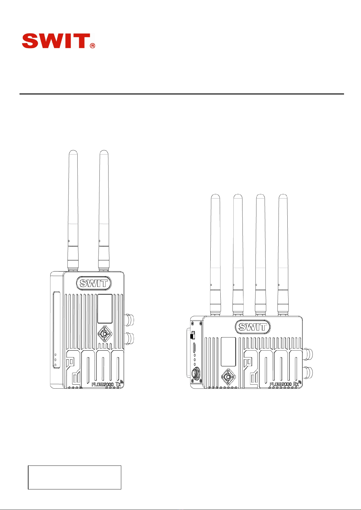
⑶Connect the Power supply of FLOW2000 transmitter and receiver, the "Power" light will light up, the OLED
screen will display " WAIT…" , and then jump to the boot interface, as shown in figure 1. Start the machine and
wait for a period of time. The transmitter and receiver have recognizable signal input and establish connection,
and the "Link" and "Video" lights are constant on. If the transmitter and receiver have recognizable signal input
but fail to establish a connection, the "Link" light will flash.
Remark:
1. When the FLOW2000 transmitter and receiver are powered, the power switch need to be set to“ON”.
2. FLOW2000 transmitter supports SDI input and HDMI input, and it will automatically detect the interface with
input video.
If both SDI and HDMI have input signal, it will give priority to SDI video, and the corresponding receiver SDI/HDMI
output interface output signal simultaneously.
6. Pairing
⑴Connect the “SDI in/HDMI in” interface of the FLOW2000 transmitter to the camera or video output device.
⑵Connect the SDI out/HDMI out interface of the FLOW2000 receiver to the SDI in/HDMI in of the monitor or
switch station.
⑶Connect the FLOW2000 transmitter and receiver power supply, The "Power"
light is on, waiting for the interface to jump to the main interface.
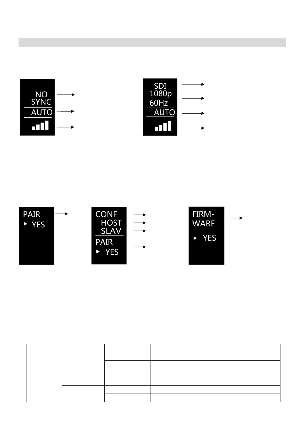
⑷Push the five-direction adjustment keys of the transmitter and receiver
respectively to the right to the "PAIR" interface, the pairing interface of the
transmitter shown in Fig 6; push down the five-direction adjustment key of
the receiver to select "YES", as shown in Fig 7. Then press down the
five-direction adjustment keys of the transmitter and receiver respectively
to select "YES" to confirm the pairing. During the pairing, the "Link" lights
of the transmitter and receiver flash quickly.
⑸After pairing successfully, the "Link" indicator stops flashing and enters the
encrypted transmission state.
Remark:
1. When pairing, the transmitter and receiver need to be paired at the same time.
2. During normal use, ensure that the wireless device used has been paired and successfully paired.
3. The paired transmitter and receiver will be automatically connected after booting up. It is no need to pair again.
4. Please keep the transmitter and receiver in distance of 1-2m to avoid pairing failure.
5. Please do not use more than 4 groups of device under the same environment to avoid interference.
Fig.6 Fig.7

6. In one transmitter to multi-receivers mode, when “SLAV” mode receiver and transmitter are paired, the "HOST"
mode receiver must be powered on.
7. The way to get the best effective of Wireless Transmission
⑴Set the antenna on both transmitter and receiver vertically straight up, no request to spread. If installed flat, still
keep the antenna vertically straight up to extend transmission distance and stabilize transmission quality. (Fig.9)
Fig.9

⑵Set the receiver as high as possible to avoid interference.
⑶Avoid walls, trees and water to reduce signal attenuation.

8. Trouble shooting
If the receiver failed to output video correctly, the possible causes are as below; please find the solution from
following chart:
The receiving
video Possible causes Solution
No display
The transmitter receiver is not
powered on Check power connection and switch on
the transmitter and receiver
The antennas are not installed properly
and screwed tightly Install the antennas properly and screw
tightly of both transmitter and receiver
Bad connection of video cable Check video cable connection of both
transmitter and receiver
Videoformatisnotsupported Change the output video format of the
camera
PoorVideoquality
Bad connection with video cable Reconnect reliably
The wireless transmission is disturbed
by environment Wait for 1 minute or reboot the
transmitter and receiver
The transmission distance is out of
effective range Close the transmitter to the receiver

9. Specification
Model FLOW2000TTransmitter FLOW2000R Receiver
Input SDI×1、HDMI×1/
Output SDI×1HDMI×1、SDI×2
Video format 1080I(60∕59.94∕50)∕ 1080PsF(24∕23.98)∕ 720P(60∕59.94∕50)∕1080P
(60∕59.94∕50∕30∕29.97∕25∕24∕23.98)
Wireless
frequency 5180~5220MHz and 5760~5820MHz
modulation mode OFDM Support 16QAM, 64QAM, QPSK, BPSKmodulation mode
transmission
distance 600m(Line of sight)
Power
consumption ≤8W ≤8W
Transmitting
power /
Human-Machine
Interaction 0.96-inch OLED Monitor, Five-direction adjustment button
Input voltage DC∕Battery:7~34V DC∕Battery :7~34V
Working
environment Temperature :0℃~+40℃
Dimension(witho
ut antenna and
plate) 66×106.5×24.7(mm)106.5×66×24.7(mm)
Net
weight(without
antenna) 236.0g 245.0g
/

the radiator& your body.
FCC Statement
Any Changes or modifications not expressly approved by the party responsible for compliance could void
the user’s authority to operate the equipment.
This device complies with part 15 of the FCC Rules. Operation is subject to the following two conditions:
(1) This device may not cause harmful interference, and
(2) This device must accept any interference received, including interference that may cause undesired
operation.
FCC Radiation Exposure Statement:
This equipment complies with FCC radiation exposure limits set forth for an uncontrolled
environment .This equipment should be installed and operated with minimum distance 20cm between
Note : This equipment has been tested and found to comply with the limits for a Class B digital device,
pursuant to part 15 of the FCC Rules. These limits are designed to provide reasonable protection
against harmful interference in a residential installation. This equipment generates,uses and can radiate
radio frequency energy and, if not installed and used in accordance with the instructions, may cause
harmful interference to radio communications. However, there is no guarantee that interference will not
occur in a particular installation. If this equipment does cause harmful interference to radio or television
reception, which can be determined by turning the equipment off and on, the user is encouraged to try to
correct the interference by one or more of the following measures:
—Reorient or relocate the receiving antenna.
—Increase the separation between the equipment and receiver.
—Connect the equipment into an outlet on a circuit different from that to which the receiver is connected.
—Consult the dealer or an experienced radio/TV technician for help.
Other manuals for FLOW2000 Series
1
Table of contents