SwitchDoc Labs WeatherSense Reference guide
Version 1.1 June 2021
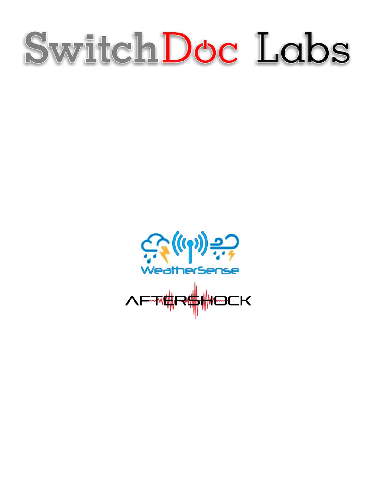
WeatherSense
Solar Powered AfterShock Earthquake Sensor
Assembly and Test Manual
June 2021
Version 1.1

Version 1.1 June 2021
Table of Contents
Cautions when building and using WeatherSense Sensors ............................................................................... 2
Errata ..................................................................................................................................................................... 2
What is The WeatherSense Solar Powered AfterShock Earthquake Detector Sensor? ................................ 6
Before You Build Your WeatherSense AfterShock System .............................................................................. 8
Step by Step Assembly and Parts List ................................................................................................................ 9
What are we doing here? .................................................................................................................................. 9
Parts List ............................................................................................................................................................ 9
Parts you need to buy separately from the kit .............................................................................................. 14
What else do you need for Assembly and Weatherproofing? ..................................................................... 15
How to select a LiPo Battery .......................................................................................................................... 15
Step by Step Assembly ........................................................................................................................................ 16
Initial Testing ................................................................................................................................................... 23
Testing WeatherSense AfterShock .................................................................................................................... 24
What does the JSON from the WeatherSense AfterShock mean? ............................................................. 26
Final WeatherProofing ....................................................................................................................................... 28
Disclaimer ............................................................................................................................................................ 29
Cautions when building and using WeatherSense Sensors
1) Keep all water away from the electronics and power supply at all times!
2) This is not a toy! Keep it out of reach of young children and pets.
3) SwitchDoc Labs assumes no liabilities in the use of this kit, beyond the refund of the purchase price.
Errata
6 Page
Version 1.1 June 2021
What is The WeatherSense Solar Powered AfterShock Earthquake Detector Sensor?
Easy to build. Easy to learn about the IoT (Internet of Things) and the Raspberry Pi.
The heart of the new WeatherSense Sensor is the our new 433MHz MiniProPlus CPU board in working in
conjunction with the SwitchDoc Labs AfterShock Earthquake Detector Board.

7 Page
Version 1.1 June 2021
The WeatherSense AfterShock kit is so simple that even middle school children can build it with just a little
adult help for configuration and installation.

8 Page
Version 1.1 June 2021
Full Open Source Arduino IDE compatible C Software that you can Modify and the open source Python3
software for the Raspberry Pi.
We provide the Python3 software (for the Raspberry Pi) and C for the WeatherSense AfterShock Earthquake
Detector. All open source with the kit. The Pure Python software can be modified to add new sensors, support
new cloud software and connect up to your own projects and software.
Before You Build Your WeatherSense AfterShock System
You should build and test your WeatherSense AfterShock system as BEFORE you put it in the optional 3D
Printed case. The WeatherSense AfterShock Assembly and Test manual will tell you how to do that. Get it
working first, then put it in the case. Believe us, it is always easier to debug the system before you close it up
in the case! All manuals are available on the WeatherSense AfterShock Product page on shop.switchdoc.com.
9 Page
Version 1.1 June 2021
Step by Step Assembly and Parts List
Cautions: Keep your static charge to a minimum during your assembly and operation. Touch metal before
handling parts. Avoid shuffling your feet. Before starting assembly, layout all the parts above and familiarize
yourself with the various parts.
What are we doing here?
We are assembling and weatherproof the WeatherSense AfterShock System.
In this manual, we are going to assemble the WeatherSense AfterShock system and test all the functions.
Parts List
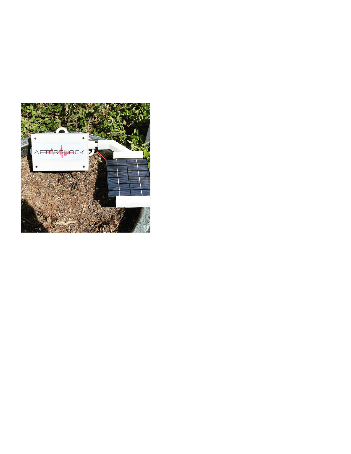
Part A
SwitchDoc Labs Grove Mini Pro Plus
Part B
Short USB A to Micro USB

10 Page
Version 1.1 June 2021
Part C
433MHz Transmitter with Antenna
Part D
AfterShock Earthquake Detection Board
11 Page
Version 1.1 June 2021
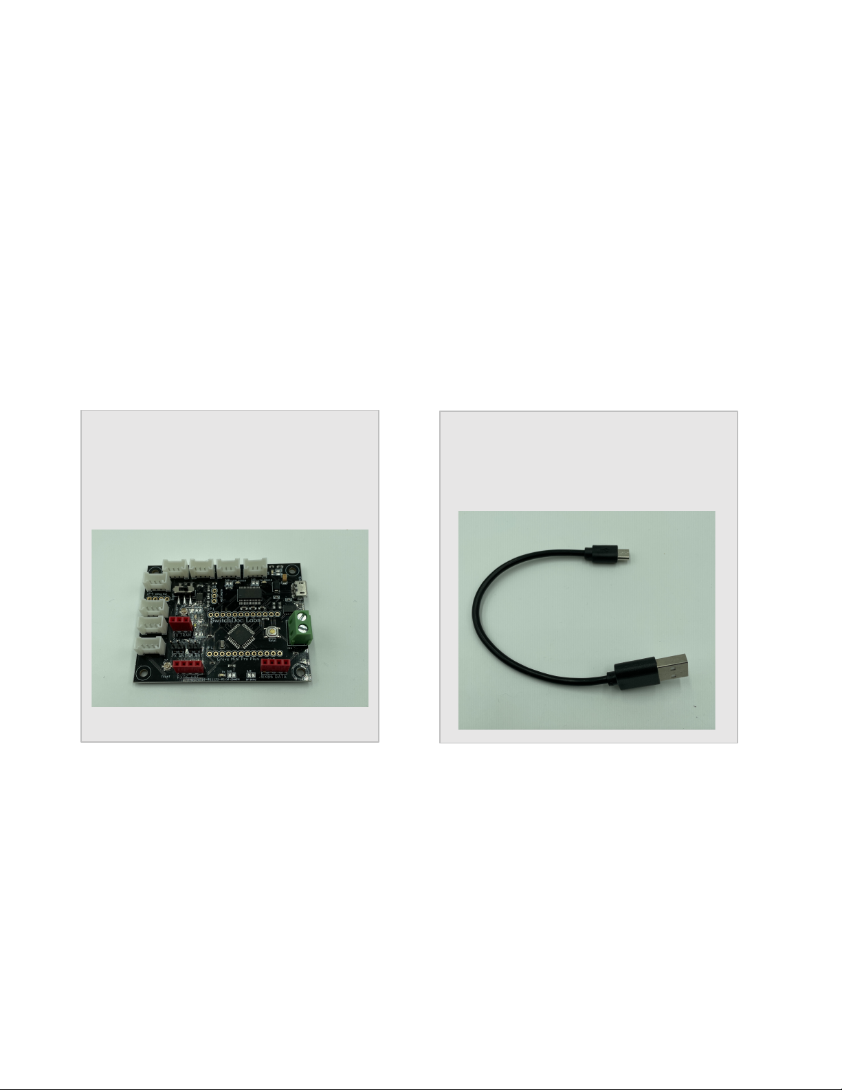
Part E
330mA 6V Solar Panel
Part F
SunAirPlus2 Solar Power Data Collector
and Controller
Part G
3.7V LiPo Battery (Not included)
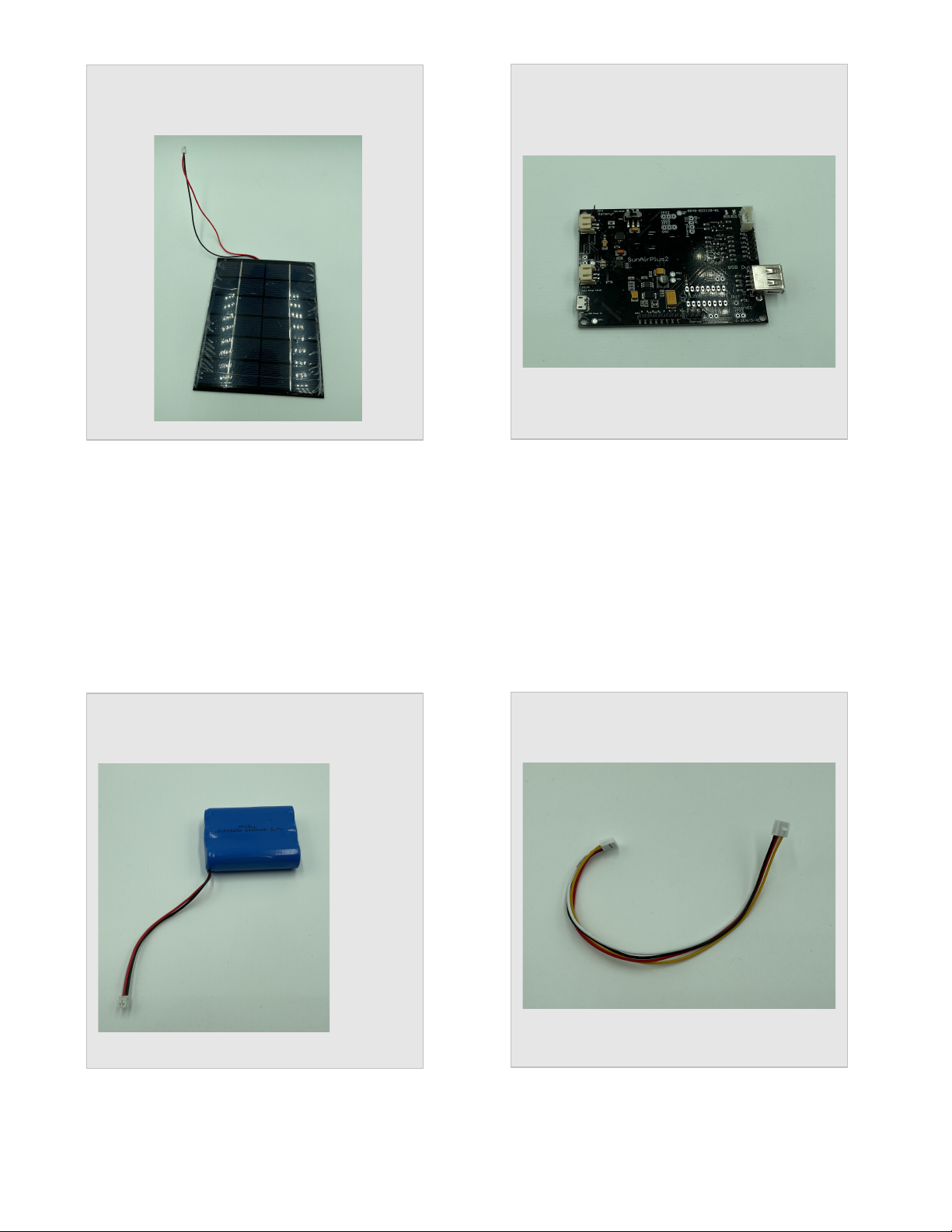
Part H
Three (3) 20cm Grove Cables

12 Page
Version 1.1 June 2021
Part I
Box Bottom
Part J
Box Top
Part K
Air Quality Housing (Not used)
13 Page
Version 1.1 June 2021
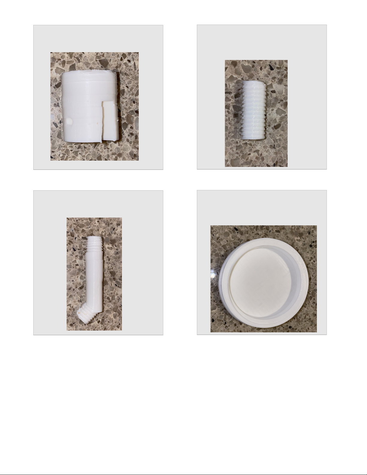
Part M
Box Plug
Part N (Combined with Part M in newer
Kits)
Joiner
Part O
Bent Joiner
Part P
Saucer Lightning Housing Top (Not
used)
Other manuals for WeatherSense
4
Table of contents
Other SwitchDoc Labs Accessories manuals


