Version 1.1 February 2021
Table of Contents
Cautions when building and using WeatherSense Sensors ............................................................................... 2
Errata ..................................................................................................................................................................... 2
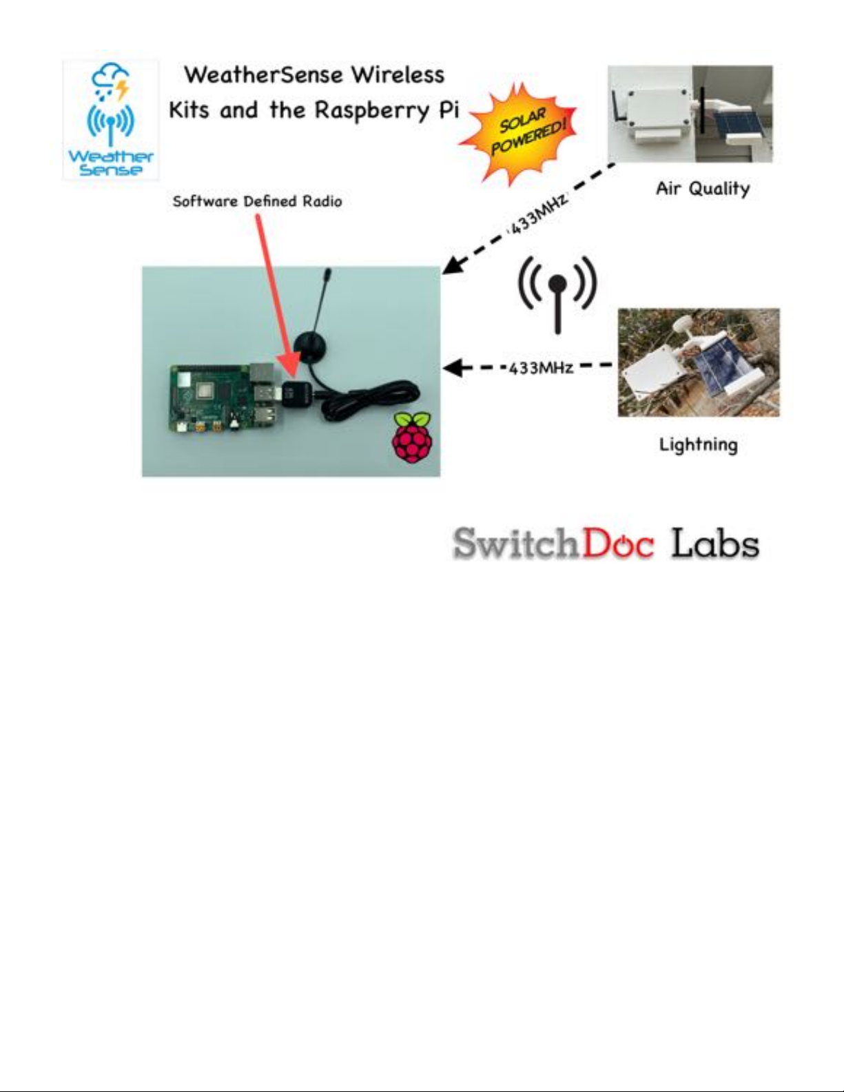
What is The WeatherSense Solar Powered Air Quality Sensor? ..................................................................... 6
Before You Build Your WeatherSense AQ ........................................................................................................ 7
Step by Step Assembly and Parts List ................................................................................................................ 8
What are we doing here? .................................................................................................................................. 8
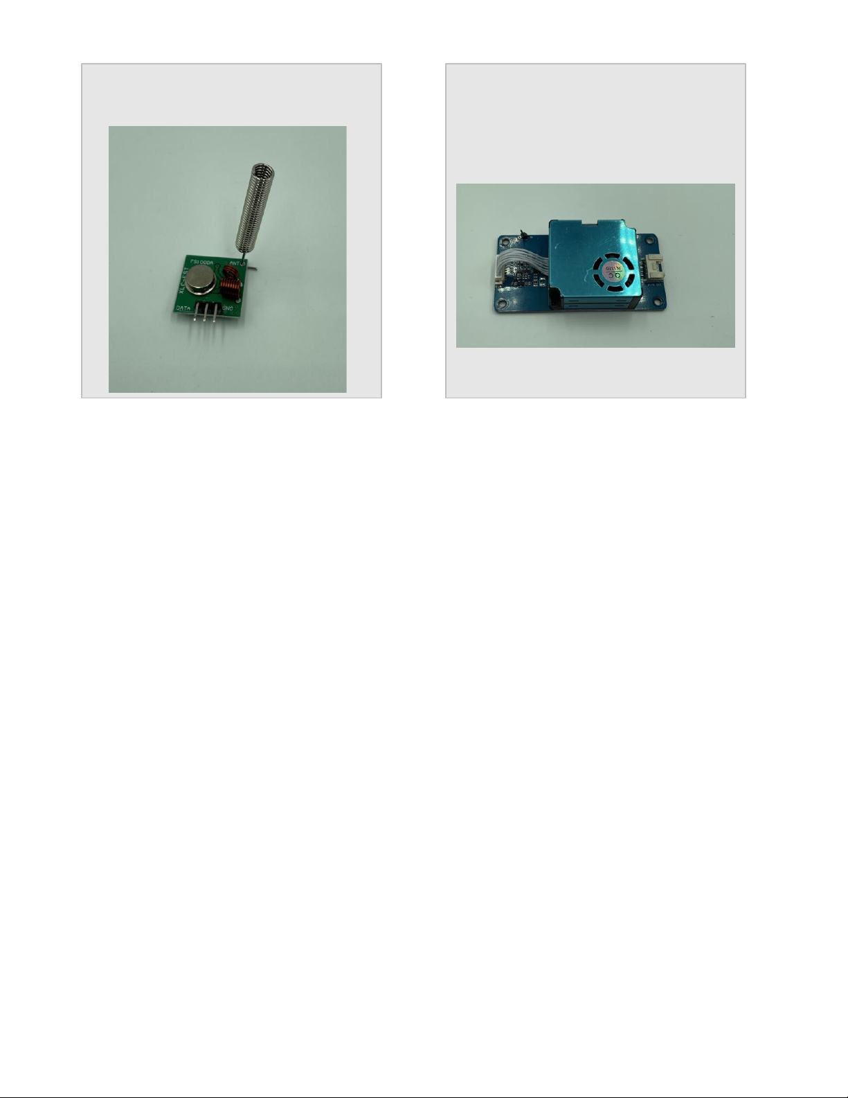
Parts List ............................................................................................................................................................ 8
Parts you need to buy separately from the kit .............................................................................................. 13
What else do you need for Assembly and Weatherproofing? ..................................................................... 13
How to select a LiPo Battery .......................................................................................................................... 14
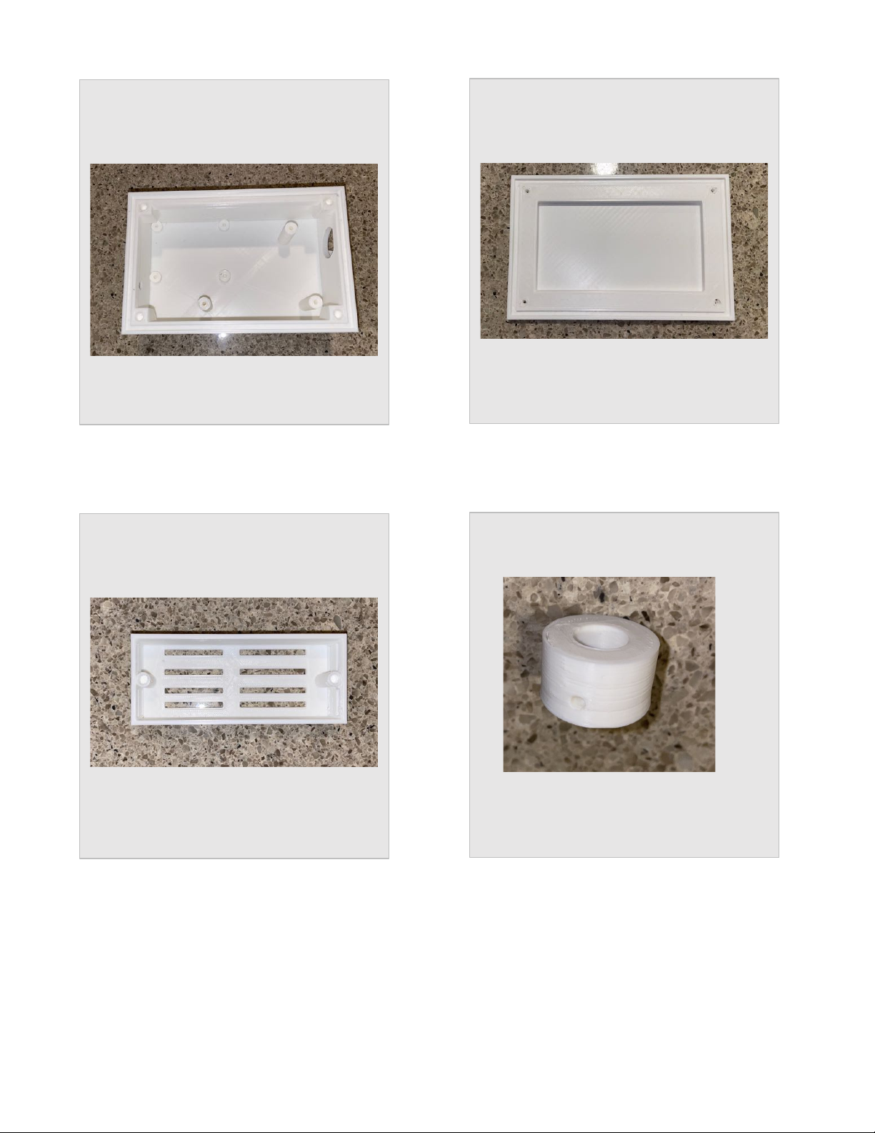
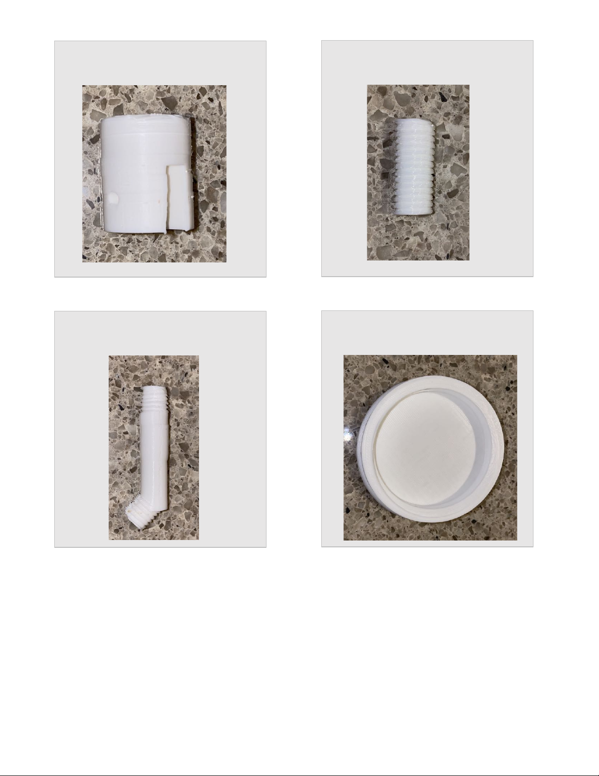
Step by Step Assembly ........................................................................................................................................ 15
Initial Testing ................................................................................................................................................... 23
What does the JSON from the WeatherSenseAQ Sensor mean? ............................................................... 25
Final WeatherProofing ....................................................................................................................................... 28
Disclaimer ............................................................................................................................................................ 29
Cautions when building and using WeatherSense Sensors
1) Keep all water away from the electronics and power supply at all times!
2) This is not a toy! Keep it out of reach of young children and pets.
3) SwitchDoc Labs assumes no liabilities in the use of this kit, beyond the refund of the purchase price.
Errata