SwitchDoc Labs WeatherSense Reference guide
Version 1.1 February 2021
WeatherSense
Solar Powered Lightning Sensor
Assembly and Test Manual
February 2021
Version 1.1

Version 1.1 February 2021
Table of Contents
Cautions when building and using WeatherSense Sensors ............................................................................... 2
Errata ..................................................................................................................................................................... 2
What is The WeatherSense Solar Powered Air Quality Sensor? ..................................................................... 6
Before You Build Your WeatherSense Lightning ............................................................................................. 7
Step by Step Assembly and Parts List ................................................................................................................ 8
What are we doing here? .................................................................................................................................. 8
Parts List ............................................................................................................................................................ 8
Parts you need to buy separately from the kit .............................................................................................. 11
How to select a LiPo Battery .......................................................................................................................... 11
Step by Step Assembly .................................................................................................................................... 12
Testing WeatherSense Lightning ...................................................................................................................... 19
What does the JSON from the WeatherSense LightningSensor mean? .................................................... 21
Optional: Reducing the power needed for your WeatherSense Lightning ........ Error! Bookmark not defined.
Disclaimer ............................................................................................................................................................ 22
Cautions when building and using WeatherSense Sensors
1) Keep all water away from the electronics and power supply at all times!
2) This is not a toy! Keep it out of reach of young children and pets.
3) SwitchDoc Labs assumes no liabilities in the use of this kit, beyond the refund of the purchase price.
Errata

6 Page
Version 1.1 February 2021
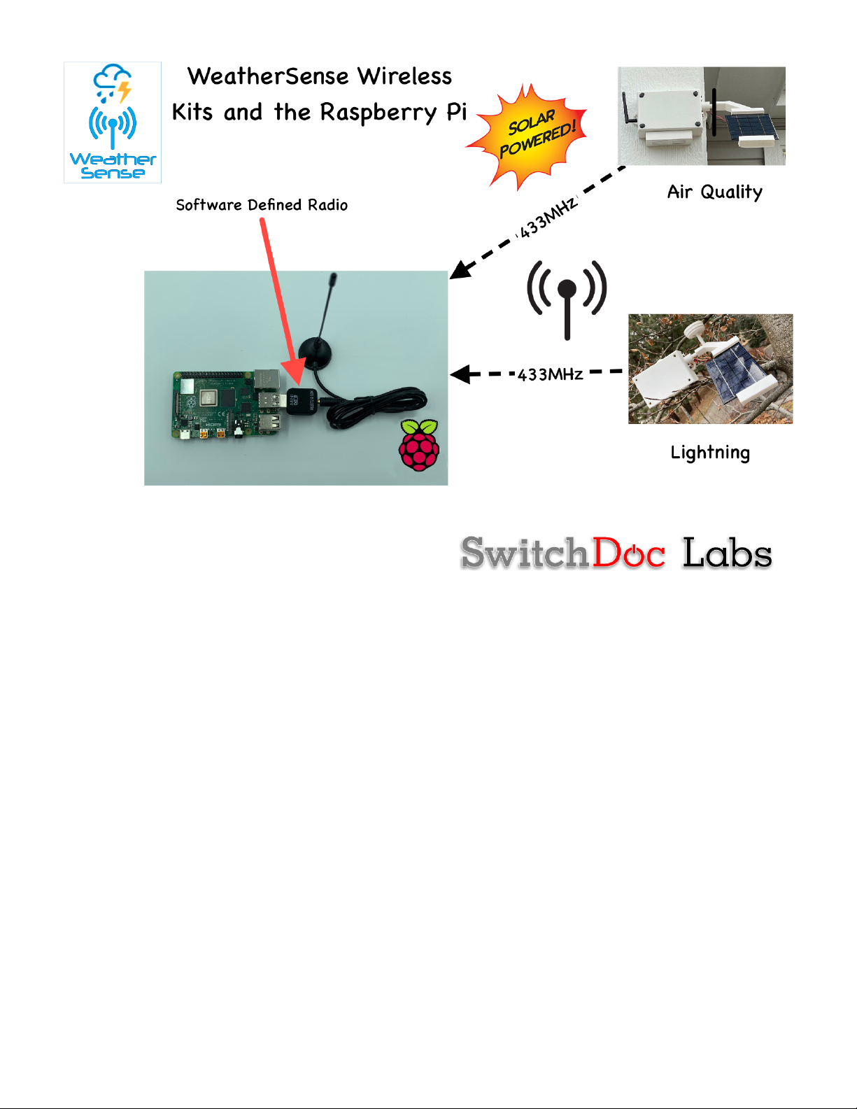
What is The WeatherSense Solar Powered Air Quality Sensor?
Easy to build. Easy to learn about the IoT (Internet of Things) and the Raspberry Pi.
The heart of the new WeatherSense Sensors is the our new 433MHz MiniProPlus CPU board in working in
conjunction with the HM3301 Laser Air Quality Sensor.
The WeatherSense Air Quality kit is so simple that even middle school children can build it with just a little
adult help for configuration and installation.
7 Page
Version 1.1 February 2021
Full Open Source Arduino IDE compatible C Software that you can Modify and the open source Python3
software for the Raspberry Pi.
We provide the Python3 software (for the Raspberry Pi) and C for the WeatherSense Lightning. All open source
with the kit. The Pure Python software can be modified to add new sensors, support new cloud software and
connect up to your own projects and software.
Before You Build Your WeatherSense Lightning
You should build and test your WeatherSense Lightning system as below BEFORE you put it in the option 3D
Printed case. Get it working first, then put it in the case. Believe us, it is always easier to debug the system
before you close it up in the case! The manual for the case and weatherproofing is called the “WeatherSense
Lightning Weatherproofing, Assembly and Test Manual”. All manuals are available on the WeatherSense
Lightning Product page on shop.switchdoc.com.

8 Page
Version 1.1 February 2021
Step by Step Assembly and Parts List
Cautions: Keep your static charge to a minimum during your assembly and operation. Touch metal before
handling parts. Avoid shuffling your feet. Before starting assembly, layout all the parts above and familiarize
yourself with the various parts.
What are we doing here?
We are assembling the WeatherSense Lightning System.
In this manual, we are going to assemble the WeatherSense Lightning system and test all the functions. If you
plan to put WeatherSense Lightning outside, and after you complete this manual, proceed to the “WeatherSense
Lightning Weatherproofing, Assembly and Test Manual” on the WeatherSense Lightning Product Page.
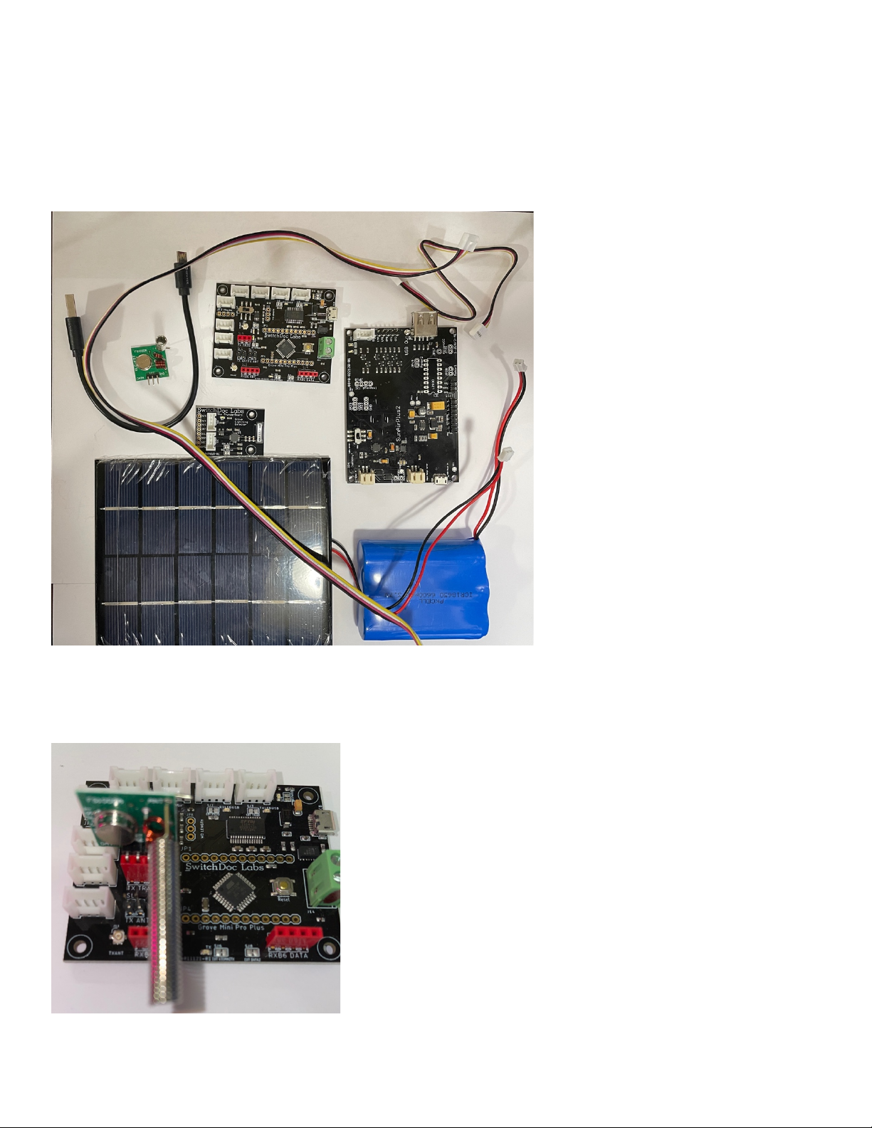
Parts List
Part A
SwitchDoc Labs Grove Mini Pro Plus
Part B
Short USB A to Micro USB

9 Page
Version 1.1 February 2021
Part C
433MHz Transmitter with Antenna
Part D
ThunderBoard Lightning Detector

10 Page
Version 1.1 February 2021
Part E
330mA 6V Solar Panel
Part F
SunAirPlus2 Solar Power Data Collector
and Controller
Part G
3.7V LiPo Battery (Not included)
Part H
One (1) 20cm Grove Cable

11 Page
Version 1.1 February 2021
Parts you need to buy separately from the kit
• 3.7V LiPo Battery
• Raspberry Pi
• Compatible SDR Software Defined Radio (For example: https://hpjhlytllzrwf4qn-
24552113.shopifypreview.com/products/software-defined-radio-sdr-and-antenna )
• 16GB SD Card (unless you bought the SD Card from SwitchDoc Labs)
• Power Supply for the Raspberry Pi
How to select a LiPo Battery
The WeatherSense Lightning requires 3.7V LiPo battery.
How large of a LiPo battery you need depends on how much sun you get and how often you have cloudy
weather. Generally, we would recommend a 6600mAh battery such as https://www.adafruit.com/product/353.
Adafruit has a great selection and you can find good ones on SparkFun.com too.
WARNING: if you get them off of Amazon, check the wiring. Most of them are wired backwards.
Here's a great website showing the problem and how to rewire the batteries if you wish:
https://docs.particle.io/tutorials/learn-more/batteries/
Part I
One (1) 50cm Grove Cable
12 Page
Version 1.1 February 2021
Step by Step Assembly
Remember you are putting together the WeatherSense Lightning to do testing and debugging. You will need to
disassemble the unit and follow the assembly instructions in the WeatherSense Lightning WeatherProofing and
System Testing Manual.
Step 1: Lay out all parts on a flat non-conductive (J) surface.
Step 2: Plug in the 433MHz Transmitter (Part C) into the MiniProPlus (Part A) three pin female header market
TX Tran. Make sure it is oriented as shown in the picture. Make sure the pins are slightly bent out as in the
second picture. This makes sure that the pins are connected in the header.

13 Page
Version 1.1 February 2021
Step 3: Take a 50cm grove cable (Part I) and plug it into the grove connection on the Mini Pro Plus (Part A)
marked J5-I2C and the other end into the I2C grove connector on the ThunderBoard Lightning (Part D). A red
dot on the bottom means that the Mini Pro Plus has been programmed as a Lightning Sensor. A White means it
has been programmed as an Air Quality Sensor.
Step 4: Push the WatchDog Time Enable Switch to the Left (enable) on the Mini Pro Plus board (Part A).
Other manuals for WeatherSense
4
Table of contents
Other SwitchDoc Labs Accessories manuals


