Swyx SX2-express SinglePRI User manual

Q U I C K S T A R T
SX2 DualPRI V2
1
SX2-express SinglePRI / SX2-express DualPRI
• Properties ofSX2-express SinglePRI / SX2-express DualPRI
ISDN Interface
• SX2-express SinglePRI: 1 x PRI interface or SX2-express DualPRI: 2 x PRI interface
• Each line can be configured individually using a jumper field for the TE or NT mode.
• Failover Relay on the SX2 DualPRI. This enables the two lines to be directly connected
to each other in the event of power failure or software problems, so that a PRI external
line can be looped through the card. This can be used for standby scenarios.
• A maximum of 4 different cards (SX2 QuadBRI, SX2 SinglePRIand SX2 DualPRI) can
be used in one PC. In doing so, a maximum of 76 B channels will be supported.
PCM Highway
• Tact synchronization only between the different SX2-express cards is possible. The
cards are connected with a ribbon cable.
• 2/4/8 Mbit/s data transfer rate
• Chipset: Exar XRT86VL
• 6 DIP Switches
• Exact 32,768 MHz quartz oscillator
• PCIe x1 Interface
General purpose I/O
• Four LEDs (red/green) on the mounting bracket of the ISDN card per PRI interface
• Four DIP switches per PRI interface that can be used for the identification of the card
• You will find more recent drivers for the SX2 in the download area of the homepage:
http://www.swyx.com/support/index.html.
• Installation of the ISDN PC Cards
The ISDN card can be installed in the same PC on which the SwyxServer is also installed. In
the standard installation, the SwyxGate service is also installed. This service controls the
ISDN lines that appear in the SwyxWare Administration as an ISDN trunk.
In order to be able to install a SwyxGate on a separate PC, the SwyxServer must already be
installed and operable. For the SwyxGate installation you will need
• the server name and
• the name of the domain account, which was created in preparation for the installation of
the SwyxServer
Before the ISDN cards are inserted, they must be configured for operation.
Mixed operation of different SX2 cards isn't possible!

Q U I C K S T A R T
SX2 DualPRI V2
2
SX2-express SinglePRI / SX2-express DualPRI
• Preparation of SX2-express SinglePRI / SX2-express DualPRI
The connection configuration must be configured for each E1 connection before it is
inserted.
Requirement for further description: The SX2-express SinglePRI / SX2-express DualPRIis
lying in front of you with the PCI plug strip facing down and the E1 connections to the left.
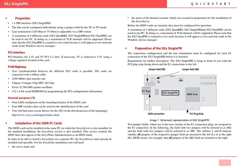
Figure 1 Schematic representation of SX2-express SinglePRI / SX2-express DualPRI
A jumper field, which are in the near vicinity of the E1 connection plug, are assigned to each
E1 connection.
PCI-express plug strip
ISDN connections
Jumper field Config 1 / 2
Connection Configuration
The connection configuration allows each E1 connection of the SX2-express SinglePRI
resp. SX2-express DualPRI to be adapted to four different cable assignments.
Figure 2 Counting pins of the connector plug (RJ45)
Jumper Pin configuration, RJ45 jack
Pin1 = TX+
Pin2 = TX-
Pin4 = RX+
Pin5 = RX-
Pin6 = TX+
Pin3 = TX-
Pin4 = RX+
Pin5 = RX-
Pin1 = RX+
Pin2 = RX-
Pin4 = TX+
Pin5 = TX-
Pin6 = RX+
Pin3 = RX-
Pin4 = TX+
Pin5 = TX-

Q U I C K S T A R T
SX2 DualPRI V2
3
SX2-express SinglePRI / SX2-express DualPRI
SwyxStandby support
The card supports the SwyxWare option pack SwyxStandby.
In order to activate this function on the SX2-express DualPRI, please make sure that the six-
pole jumper is inserted between the two ISDN connections. If this jumper is not present, the
card cannot support the standby option.
For information on configuring the SX2-express DualPRI before insertion, so that the
existing relay can be used, please refer to the SwyxWare documentation.
Jumper to support SwyxStandby (Config 3).
Configuration of the card number
You can set the card number with the six-pole DIP switch in the upper middle of the SX2-
express SinglePRI / SX2-express DualPRI.
Only DIP switches 1 to 4 are used. The following assignment is valid:
If you use several cards in one system, please make sure that either one card number was
assigned for all cards, or automatic card number assignment is set for all cards.
Switch 1 Switch 2 Switch 3 Switch 4 Card number
on off off off 1
off on off off 2
on on off off 3
off off on off 4
on off on off 5
off on on off 6
on on on off 7
off off off on 8
on off off on 9
off on off on 10
on on off on 11
off off on on 12
on off on on 13
off on on on 14
on on on on 15
off off off off assigned automatically
Configuration of the card number

Q U I C K S T A R T
SX2 DualPRI V2
4
SX2-express SinglePRI / SX2-express DualPRI
PCM bus connection
The SX2-express SinglePRI / SX2-express DualPRI has two 20-pole jacks for connection
with an optional PCM cable.
The upper jack is the output. The lower jack is the input. Connect the SX2 cards with the
PCM cable, by connecting the output jack of one card to the input jack of another card.
LED Status Display
Each E1 connection of the SX2-express SinglePRI / SX2-express DualPRI has a status
display consisting of two red and two green LEDs.
The following assignments are valid:
LED LED Statement
1 off Layer 1 deactivated
1 red glowing Layer 1 activated
2 green glowing Layer 2 activated
3 green, blinking At least one connection is active
4 red, blinking The line is being configured
PCM input PCM output
• Insertion of the ISDN Card
The insertion of the ISDN cards is nearly identical and therefore they are explained together
in this chapter.
After the card has been installed physically, it will automatically be recognized the next time
the computer is booted and a request for the installation of the driver software will appear.
You may find more recent drivers for the ISDN cards in the download area of the homepage:
http://www.swyx.com/support/index.html.
Do the necessary hardware configuration before the insertion. For further information,
please refer to the SwyxWare Administrator documentation.
It is absolutely necessary that you turn off the PC and remove the mains plug from the
power supply whenever you are doing something which requires you to open the PC case!
Do not touch any of the electronic components of the PC card during the entire installation
process. The electronic components of the PC card can be damaged by electrostatic
discharges!
For safety reasons, it is necessary that you disconnect all connection cables from the
telephone network before you open the PC case.
This is how you install the ISDN cards in your PC
1. Turn off your PC and pull the respective mains plug out of the socket.
2. Open your PC.
3. Remove the screw from the metal panel covering a free PCI-express (expansion) slot:
Figure 3 Removing the Metal Panel
4. Insert the ISDN PC card into a free PCI or PCI-X plug-in slot.
5. Use the screw you just removed to secure the PC card.
Metal Panel
Expansion Slot
ISA
16-bit Expansion Slot
PCI /PCI-X
slot
Case
Back

Q U I C K S T A R T
SX2 DualPRI V2
5
SX2-express SinglePRI / SX2-express DualPRI
6. Connect the SX2 DualPRI to the PRI ISDN connections using the cable which has been
supplied.
Figure 4 Connecting the ISDN Cable
7. Close your PC and restore the power supply by plugging in the mains plug.
• Installation of the software for the ISDN card
After the card has been installed, it will automatically be recognized the next time the
computer is booted and a request for the installation of the driver software will appear.
This is how you install the drivers for the ISDN card
1. Follow the instructions given by the hardware wizard.
2. When you are asked to enter the source for the driver, select “Enter other source”.
3. Put the SwyxWare CD in your CD ROM drive.
Click on ”Next >”.
4. Enter the path on the SwyxWare CD for the driver files on the SwyxWare CD
"\ISDN\SX2 Standard Driver"
During the installation of the driver you will be asked to enter the ISDN switching type or
the D-channel protocol.
5. Select the ISDN exchange type or the switch protocol used by your telephone company
(in Europe this is Euro-ISDN (DSS1)).
Click on ”Next >”.
6. Follow the wizard’s instructions and then click on “Finish” in the dialog “Completing
the wizard”.
You can check to see if the driver installation was successful by checking the entries in the
Device Manager in the ‘Network Cards’ category. You will find more information on the
Device Manager under SwyxWare documentation.
You can check whether the installed ISDN cards functions properly by using the utilities
supplied on the SwyxWare CD. For further information please refer to the SwyxWare
documentation.
• Configuration of the ISDN Card
If you would like to connect the card to a direct dialing in line, you must make some
configuration changes fort he ISDN PC card driver.
You can change the defined parameters in the driver software of the ISDN card at a later
point in time.
This is how you modify the ISDN PC card driver configuration
1. Run computer management, the simplest possibility is to use the shortcut menu for "My
Computer" on the Windows Desktop
2. Select “Manage”.
The Microsoft Management Console (MMC) will be started.
3. Select “Device Manager” in the console structure.
A list of all installed devices will now be shown on the right. There you will find the
following entry under “Network Cards”: “SX2 DualPRI".
4. Enter the appropriate settings under “Properties”:
• Select “ISDN Parameters” on the “Advanced” tab.
Select the “Port” tab in the dialog which is displayed.
• To switch to a line configured for direct dialing-in, please choose “Point to Point” and
close both this tab and the previous tab by clicking on “OK”.
Tip: If the line of an SX2 card is configured, the LED which is associated with this line will
blink. This simplifies the identification when operating several SX2 cards.
Configuration of the Line Termination
The line termination will be configured in the software settings. Default value: 120
Ohm.
This is how you change the line termination of SX2-express SinglePRI resp. SX2-
express DualPRI
1. Run computer management, the simplest possibility is to use the shortcut menu for "My
Computer" on the Windows Desktop
2. Under "ISDN Controller" switch to the corresponding SX2-express board.
3. There are settings for each Controller. On the right side mark the controller and choose
the line termination you want in the dropdown list.
You can choose between 120, 110,100 and 75 Ohm.
4. Save the changes with "OK" and close the Device Manager.
This manual suits for next models
1
Table of contents
Other Swyx Computer Hardware manuals
Popular Computer Hardware manuals by other brands

Texas Instruments
Texas Instruments INA234EVM user guide

Sony
Sony BKMW-E3000 installation manual

DMP Electronics
DMP Electronics XR500 SERIES Programming guide

Addonics Technologies
Addonics Technologies ADST114R5 Installations and specifications

Supermicro
Supermicro X13QEH+ user manual

Noctua
Noctua NH-U12S DX-3647 installation manual