EN
7
For parameter export to the SD card, DIN 6 has to be configured for Parameter export and 24 V must be
connected to DIN 6. In addition a restart of the frequency inverter or a reset via a digital input must be
initiated.
Successful parameter export is signaled by three flashes of the green LED, an export error with three
flashes of the red LED.
Only the motor parameter set is saved on the micro SD card; the settings for the inputs and outputs
remain as they were.
Only use the micro SD card provided, as a different micro SD card may not be readable by the inverter.
12.0 SycoDrive Operating Software
For the operation and configuration of the frequency inverter, you will need a USB cable and a PC or tablet.
The mini USB cable included in the scope of supply can be used to connect the PC to the frequency inverter.
You will also need the SycoDrive operating software, which can be downloaded free of charge from the
website www.sycotec.eu.
Connection:
Install the SycoDrive operating software on your PC
Open SycoDrive
Switch on the frequency inverter
Connect the PC to the frequency inverter (the frequency inverter will detect the COM port
automatically).
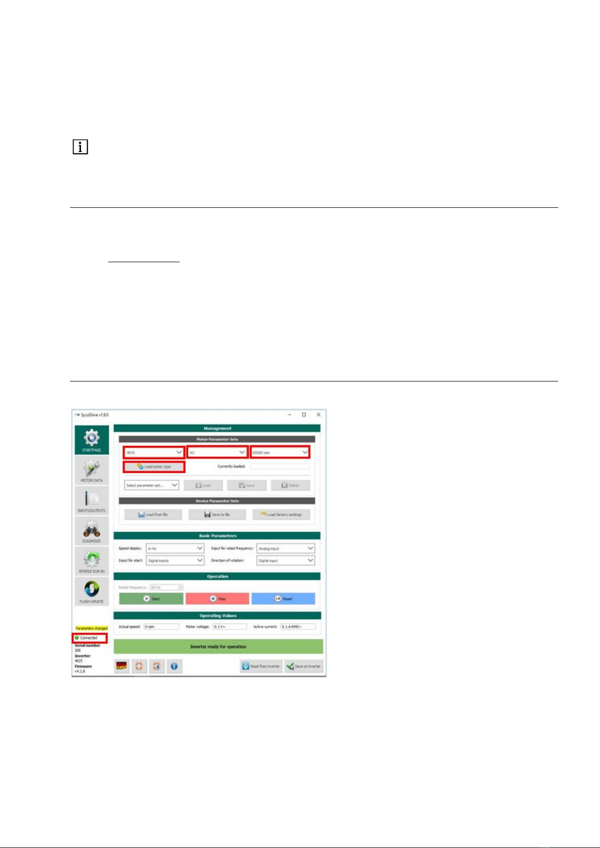
12.1 Configuration and Commissioning
The current connection status is displayed on the left on the bottom half of the user interface.
Once the inverter has been connected to the PC, select the desired type of motor from the "STARTPAGE"
under "Management" and then confirm the selection with the "Load motor type" button.
This will initially load the motor parameters into the SycoDrive user interface.
These are not yet active in the inverter.
The "Save on inverter" button then transfers the parameters from the SycoDrive user interface to the
frequency inverter.