SycoTec easyDrive 4330 IP00 User manual

Object description UART Interface EN
HF Inverter @syDrive® 4330 (IP00), 4330-H (IP10)

EN
ATTENTION
This UART Interface object description is only valid in connection with the
operating manual of HF Inverter e@syDrive 4330, 4330-H
(material no. 2. 003.6718)!
The safety information must be observed before commissioning!

EN
Table of Contents
1USER INFORMATION ......................................................................................................................4
1.1 SYMBOLS USED .............................................................................................................................. 4
1.2 SCOPE OF SUPPLY .......................................................................................................................... 4
1.3 IMPORTANT INFORMATION........................................................................................................... 4
1.4 INTENDED USE ............................................................................................................................... 4
2INTERFACE SETTINGS .....................................................................................................................5
3UART ZDC COMMANDS..................................................................................................................5
4GENERAL INFORMATION................................................................................................................5
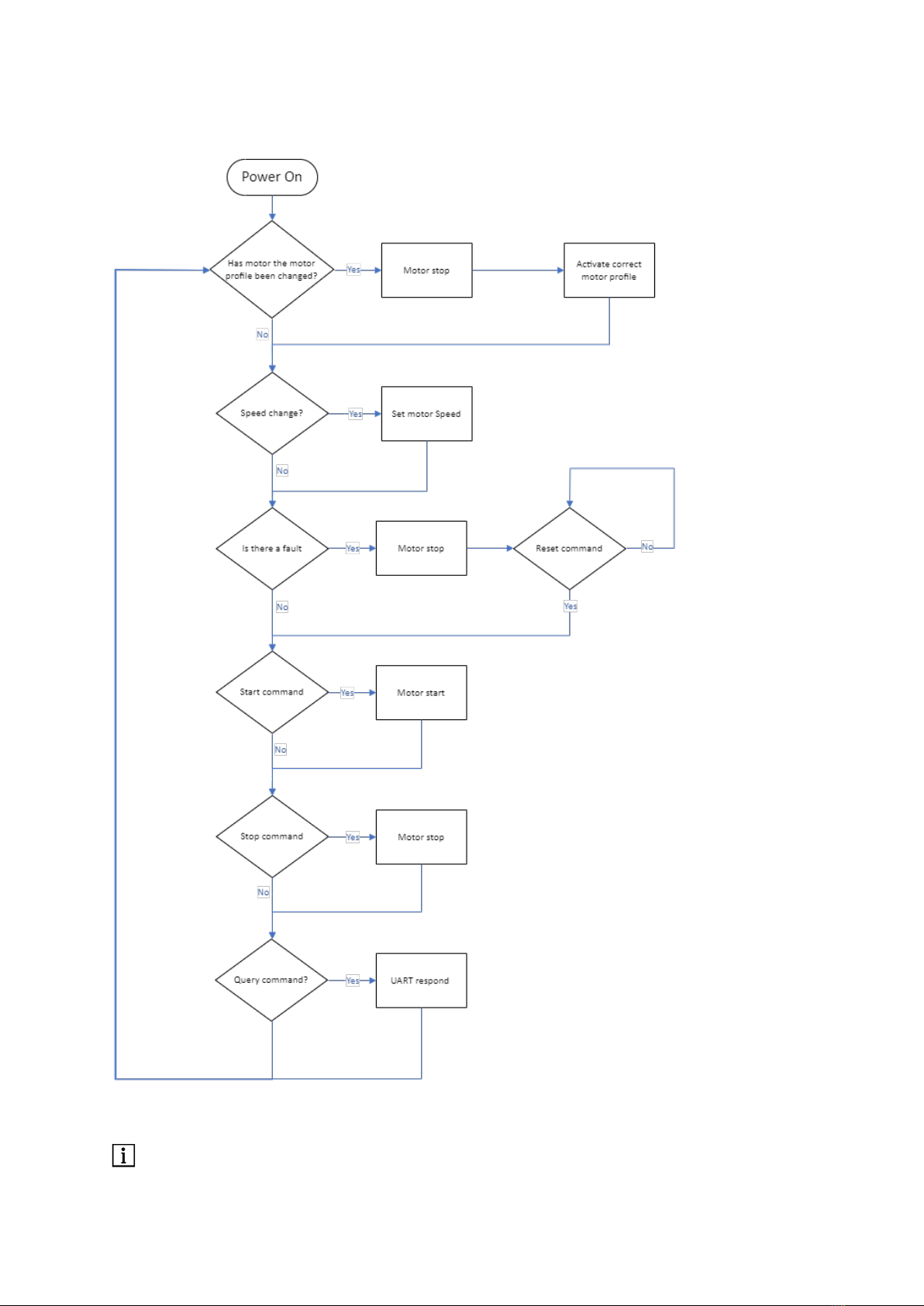
5STATE MACHINE.............................................................................................................................6
6QUERY FIRMWARE/HARDWARE VERSION .....................................................................................7
7QUERY HARDWARE IDENTIFIER......................................................................................................8
8START MOTOR ...............................................................................................................................8
9STOP MOTOR .................................................................................................................................9
10 SET SPEED ......................................................................................................................................9
11 CHANGE MOTOR PROFILE ............................................................................................................10
12 RESET INVERTER...........................................................................................................................10
13 QUERY SPEED...............................................................................................................................11
14 QUERY STATUS.............................................................................................................................12
15 QUERY INTERNAL STATUS............................................................................................................13
16 QUERY POWER.............................................................................................................................14
17 QUERY BUS VOLTAGE...................................................................................................................15
18 QUERY CURRENT..........................................................................................................................16
19 QUERY MOTOR TEMPERATURE....................................................................................................17
20 QUERY INVERTER TEMPERATURE.................................................................................................18
21 QUERY NAME...............................................................................................................................19
WARRANTY CONDITIONS.....................................................................................................................20

EN
4
1User information
1.1 Symbols used
Operating manual
ATTENTION
Indicates a hazardous situation that can cause damage to property or
mild to moderate injuries.
Important information for operator and engineer
1.2 Scope of supply
Material no.
UART Interface object description
2.003.6927
The current operating manuals and descriptions can be downloaded from the SycoTec website under
Downloads - SycoTec GmbH & Co. KG.
1.3 Important information
Target group: This document is intended for machine manufacturers and persons responsible for putting into
service and operating the frequency inverter e@syDrive 4330, 4330-H.
ATTENTION
The operating manual must be read by the user/operator before starting up the unit for the first time in
order to avoid incorrect operation and other damage. Duplication and distribution of the operating
manual require SycoTec’s prior consent.
All specifications, information and properties of the product described in the operating manual correspond to the
status on going to press.
Modifications and improvements to the product as a result of new technical developments are possible.
This does not imply any right to retrofitting of existing units.
SycoTec assumes no responsibility for damage arising through:
•Use of incorrect information
•Improper use
The safety and application instructions in the hardware description and in the software description of the
frequency inverter must be observed!
The software and firmware version must be compatible with each other.
1.4 Intended use
The UART Interface is used for commissioning and operating of following SycoTec frequency inverters:
Material no.
HF inverter e@syDrive 4330 (IP00)*
2.003.3952
HF inverter e@syDrive 4330 (IP00) - C**
(customized parameter-setting)
2.003.6383
HF inverter e@syDrive 4330-H (IP10)*
2.003.5721
HF inverter e@syDrive 4330-H (IP10) - C**
(customized parameter-setting)
2.003.6378
* Preset with default list of parameter settings. No spindle-profile activated. Profile have to be activated via Software.
** Customer specific parameter installed and activated.

EN
5
This document is valid for all hardware versions.
This document is valid for all following firmware versions:
Firmware version
Remarks
From V1.0 to the latest version
All in this document mentioned commands are
possible
2Interface settings
Baud Rate
115200
Data Bits
8
Parity
None
Stop Bits
1
3UART ZDC Commands
Command
Description
0x0D
Query firmware/hardware version
0x10
Query hardware identifier
0x24
Start motor
0x25
Stop motor
0x01
Set speed
0x90
Change motor profile
0x39
Reset inverter
0x42
Query Speed
0x60
Query status
0xF1
Query internal status
0x70
Query power
0x72
Query bus voltage
0x74
Query current
0x75
Query motor temperature
0x76
Query inverter temperature
0x77
Query name
4General information
A response of a command is only an acknowledgement of receipt and is not a confirmation that the command was
executed successfully. For the confirmation the status of each command sent is required. E.g. if you wanted to set
the speed, you should send the "Query Speed" command and compare the values set against the values received.

EN
6
5State machine
All commands such as the Query commands can be done at any time.
The motor will stop if the motor profile is changed.

EN
7
6Query firmware/hardware version
SEND:
HEX CODE
Description
0x0D
Query firmware/hardware version
RECEIVE:
HEX CODE
Description
0xDD
Successful reception of the command
SVL
Low byte of the software ident number
SVH
High byte of the software ident number
SVC
Software version
HVL
Low byte of the hardware ident number
HVH
High byte of the hardware ident number
HVC
Hardware version
Detailed information and example which information will be received:
Send:
0x0D
Receive:
0xDD
0x7B
0x00
0x01
0x01
0x00
0x00
DL
DH
SW Version
HWID DL
HWID DH
HW ID
Result in HEX:
0x00
0x7B
0x01
0x00
0x01
0x00
DH
DL
D
DH
DL
HW ID
Result in DEC:
123 = Software ID
1 = SW Version
1 = Hardware Version
Hardware ID

EN
8
7Query hardware identifier
Each hardware manufacturer responds to the 0x10 command with its own code:
SEND:
HEX CODE
Description
0x10
Query the board
0x00
Always zero
0x00
Always zero
RECEIVE:
HEX CODE
Description
0xC0
Successful reception of the command
0x02
Low byte of the hardware identifier
0x00
High byte of the hardware identifier
Response is always 0x02
0x02 = Inverter SySyC2-D/E
8Start motor
SEND:
HEX CODE
Description
0x24
Start Motor
RECEIVE:
HEX CODE
Description
0xE4
Successful reception of the command
DL
Low byte of the set speed
DH
High byte of the set speed
Received value RPM*10 is set speed.
ATTENTION
After the command "Start" 0x24h, please make sure that the status word is continuously queried.
Otherwise, a spindle stop is automatically triggered after 2sec to ensure that the spindle does not continue
to run uncontrolled in the event of a loss of communication with the inverter.

EN
9
9Stop motor
SEND:
HEX CODE
Description
0x25
Stop Motor
RECEIVE:
HEX CODE
Description
0xE5
Successful reception of the command
0x00
Low byte of the speed = 0
0x00
High byte of the speed = 0
10 Set speed
SEND:
HEX CODE
Description
0x01
Set speed
DL
Low byte of the desired speed
DH
High byte of the desired speed
RECEIVE:
HEX CODE
Description
0xC1
Successful reception of the command
DL
Low byte of the set speed
DH
High byte of the set speed
The device interprets the sent speed as RPM*10
Example:
Send:
0x01
0xA0
0x0F
Receive:
0xC1
0xA0
0x0F
DL
DH
Result in HEX:
0x0F
0xA0
DH
DL
Result in DEC:
4,000 -> 4,000*10 RPM = 40,000 RPM
E.g.: For a speed of 40,000 rpm 0x01 0xA0 0x0F (4000d) must be sent.

EN
10
11 Change motor profile
SEND:
HEX CODE
Description
0x90
Motor profile change
0xXY
Spindle code (See spindle table)
RECEIVE:
HEX CODE
Description
0x09
Successful reception of the command
0xXY
Set spindle motor (spindle table)
SPINDLE TABLE:
Spindle Name
Spindle Code
Motor 1 Position
0x00
Motor 2 Position
0x01
Motor 3 Position
0x02
Motor 4 Position
0x03
Motor 5 Position
0x04
Motor 6 Position
0x05
12 Reset inverter
SEND:
HEX CODE
Description
0x39
Reset inverter
0x07
Low Byte
0x77
High Byte
RECEIVE:
HEX CODE
Description
0x93
Successful reception of the command
0x77
Low Byte
0x07
High Byte
Used to reset the inverter and the set values.

EN
11
13 Query speed
SEND:
HEX CODE
Description
0x42
Query speed
RECEIVE:
HEX CODE
Description
0xC2
Successful reception of the command
DL
Low Byte of the speed
DH
High Byte of the speed
Received value rpm*10 is the current speed.
Send:
0x42
Receive:
0xC2
0xA0
0x0F
DL
DH
Result in HEX:
0x0F
0xA0
DH
DL
Result in DEC:
4000 -> 4000*10 RPM = 40,000 RPM

EN
12
14 Query status
SEND:
HEX CODE
Description
0x60
Query Status
RECEIVE:
HEX CODE
Description
0xE0
Successful reception of the command
DL
Low byte of the status code
DH
High byte of the status code
Status word description
Bit Position
Name
Description
1
Start Stop
Status Start/Stop
2
Motor Connected
No motor connected
5
At Speed Description
Status Set speed reached after running,
high =at speed, low = not at speed
6
Stopped
Spindle stop status, states if the motor has fully stopped spinning
7
Undervoltage
Undervoltage from the 48V power supply
8
Overvoltage
Overvoltage from the 48V power supply
12
Inverter
Error signal from inverter.
The inverter fault goes "high" for any fault, but includes faults not
stated such as a start fault or a motor stalled fault.
13
Overload
Status overload (over current or overpower)
If a critical status (e.g. undervoltage, overvoltage, overload or overtemperature) occurs, then the control is
stopped and the red LED is activated.
To ensure that the motor stars after a fault, send a reset command.
A reset command will also reset the status.
Example:
The status code when the motor is stopped is 0x2040 = 8256 in Decimal (Overload and stopped).
Bit
15
14
13
12
11
10
9
8
7
6
5
4
3
2
1
0
Level
0
0
1
0
0
0
0
0
0
1
0
0
0
0
0
0
hex
2
0
4
0

EN
13
15 Query internal status
SEND:
HEX CODE
Description
0xF1
Query internal status
0x00
Query internal status
0xFF
Query internal status
RECEIVE:
HEX CODE
Description
0xFA
Successful reception of the command
DL
Low byte of the internal status code
DH
High byte of the internal status code
If the response is 0x0000, the status is OK.
Otherwise: see description of the internal status code in the following table
Bit Position
Name
Description
0
Undervoltage status
Undervoltage from the 48V power supply
1
Status overvoltage
Overvoltage from the 48V power supply
2
Status overload
Over current or overpower fault
8
Status reserved
Status reserved
9
Status reserved
Status reserved
10
Status reserved
Status reserved
11
Status reserved
Status reserved
Example:
The internal status code in case of overvoltage is 0x0002
Bit
15
14
13
12
11
10
9
8
7
6
5
4
3
2
1
0
Level
0
0
0
0
0
0
0
0
0
0
0
0
0
0
1
0
hex
0
0
0
2

EN
14
16 Query power
SEND:
HEX CODE
Description
0x70
Query power in W
RECEIVE:
HEX CODE
Description
0x07
Successful reception of the command
DL
Low byte of the power
DH
High byte of the power
Calculates the power using the phase current and the phase voltage.
This is calculated every 5th step of the motor.
Example:
Send:
0x70
Receive:
0x07
0x1B
0x00
DL
DH
Result in HEX:
0x00
0x1B
DH
DL
Result in DEC:
27 = 27 W

EN
15
17 Query BUS voltage
SEND:
HEX CODE
Description
0x72
Query BUS voltage
RECEIVE:
HEX CODE
Description
0x27
Successful reception of the command
DL
Low byte of the BUS voltage
DH
High byte of the BUS voltage
Received value V*0.1 is the current BUS-voltage.
Example
Send:
0x72
Receive:
0x27
0xE0
0x01
DL
DH
Result in HEX:
0x01
0xE
DH
DL
Result in DEC:
480 → 480*0.1 V = 48.0 V

EN
16
18 Query current
This command displays the actual output current Ph-Ph of the motor.
SEND:
HEX CODE
Description
0x74
Query motor current (in 0,1A)
RECEIVE:
HEX CODE
Description
0x47
Successful reception of the command
DL
Low Byte of current
DH
High Byte of current
Received value A*0.1 is the current.
Example:
A current of 2.6 A is measured and is to be read out.
Send:
0x74
Receive:
0x47
0x1A
0x00
DL
DH
Result in HEX:
0x00
0x1A
DH
DL
Result in DEC:
26 -> 26*0.1A = 2.6 A

EN
17
19 Query motor temperature
SEND:
HEX CODE
Description
0x75
Query motor temperature
DL
Low Byte of the motor temperature value
DH
High Byte of the motor temperature value
RECEIVE:
HEX CODE
Description
0x57
Successful reception of command
DL
Low Byte of the motor temperature value
DH
High Byte of the motor temperature value
This will display the resistor of the temperature sensor (motor) in Ohms.
The motor temperature will only be read if the motor profile states that it should.
If the motor temperature sensor is not connected, and the motor profile dictates that there should be a value,
the inverter will flag a fault.
If the motor profile dictates that there shouldn’t be a temperature sensor and there is a temperature sensor
connected, the temperature will not be read.
Example:
Send:
0x75
Receive:
0x57
0x81
0x02
DL
DH
Result in HEX:
0x02
0x81
DH
DL
Result in DEC:
641 = 641 Ohm

EN
18
20 Query inverter temperature
SEND:
HEX CODE
Description
0x76
Query inverter temperature
DL
Low Byte of the inverter temperature value
DH
High Byte of the inverter temperature value
RECEIVE:
HEX CODE
Description
0x67
Successful reception of the command
DL
Low Byte of the inverter temperature value
DH
High Byte of the inverter temperature value
This will display temperature in degrees Celsius (°C).
Example
Send:
0x76
Receive:
0x67
0x19
0x00
DL
DH
Result in HEX:
0x00
0x19
DH
DL
Result in DEC:
25 = 25 degrees Celsius

EN
19
21 Query name
SEND:
HEX CODE
Description
0x77
Query name
RECEIVE:
HEX CODE
Description
0x77
Successful reception of the command
0x53
Byte 0 of the name ‘S’
0x59
Byte 1 of the name ‘Y’
0x43
Byte 2 of the name ‘C’
0x34
Byte 3 of the name ‘4’
0x33
Byte 4 of the name ‘3’
0x33
Byte 5 of the name ‘3’
0x30
Byte 6 of the name ‘0’
0x2D
Byte 7 of the name ‘-‘
0x44
Byte 8 of the name ‘D’
0xXX
Random number
0xXX
Random number
0xXX
Random number
0xXX
Random number
0xXX
Random number
0xXX
Random number
0xXX
Random number
This displays the inverters name, it could be useful for confirming the hard ware.

EN
Warranty Conditions
Under current SycoTec delivery and payment conditions, SycoTec undertakes warranty for satisfactory function
and freedom from faults in material and manufacture for a period of 12 months from the date of sale certified by
the vendor.
In the event of justifiable complaints, SycoTec shall supply spare parts or carry out repairs free of charge under
warranty. SycoTec accepts no liability for defects and their consequences which have arisen or could have arisen as
a result of natural wear and tear, improper handling, cleaning or maintenance, non-compliance with the
maintenance, operating or connecting instructions, corrosion, impurities in the air supply or chemical or electrical
influences which are unusual or not admissible in accordance with SycoTec's standards. The warranty claims shall
become null and void if defects or their consequences can be attributed to interventions in or modifications to the
product. Warranty claims can only be validated if they are notified immediately in writing to SycoTec.
A copy invoice or delivery note clearly showing the manufacture number shall be attached if products are
returned.
2.003.6927 –2023-09
(EN = original)
Other manuals for easyDrive 4330 IP00
1
This manual suits for next models
1
Table of contents
Popular Recording Equipment manuals by other brands

Yamaha
Yamaha POCKETRAK C24 Service manual

Maple Systems
Maple Systems HMI5000P Series installation guide

Iso-Max
Iso-Max Pro Series user guide

Disaster Area Designs
Disaster Area Designs DMC-3XL Gen2 quick start guide

auto maskin
auto maskin Marine Pro. 400 Series installation manual

Enabling Devices
Enabling Devices 1165 user guide