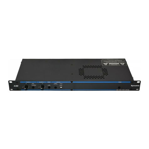
Symetrix 420 User manual

!
"
!
"
#$
!
"
%&'()
Symetrix
420
Stereo Amplifier
*+,,
-&./&
0/1&.+
23& !"0.&$4+))&&&+
5&)+6&'&7
)/)#&&&+

Production Information
This document was written using Microsoft Word for Windows V2.0 and 6.0. The drawings and graphs in
this manual were prepared using Corel Draw V2.0, Autocad V12, and Autoscript V5, then imported into
Word for Windows via encapsulated PostScript files. All page makeup occurred within Word for Windows.
Body text is set in Bookman 10pt and Section Heads are set in various sizes of Helvetica Bold. Helvetica-
Narrow was used for Figure and Table captions.
This manual was printed directly from PostScript files generated by Word for Windows on a Xerox
Docutech printer. This unique device is actually a laser printer, capable of 600 dpi resolution, with a page
throughput that rivals a high-speed photocopier. As a result, every page is a first-generation image.
Ain’t technology grand?

i
Table of Contents
1. Introduction............................................................................................. 1-1
1.1 Manual Sections................................................................................................1-2
1.2 Operator Safety Summary ................................................................................1-2
1.2.1 Terms.......................................................................................................1-3
1.3 Other Safety Information...................................................................................1-3
2. Basics...................................................................................................... 2-1
2.1 What is a Power Amplifier?............................................................................... 2-1
2.2 Amplifier Output Limitations..............................................................................2-1
2.3 Mono-Bridged Operation...................................................................................2-2
2.4 Driving Loudspeakers .......................................................................................2-3
2.5 A Word About Wire ...........................................................................................2-3
2.6 Driving Headphones..........................................................................................2-3
2.7 The Great Gain Control Mystery.......................................................................2-4
3. Technical Tutorial................................................................................... 3-1
3.1 Matching Levels vs Matching Impedances .......................................................3-1
3.2 Signal Levels..................................................................................................... 3-2
3.3 I/O Impedances.................................................................................................3-2
3.4 Polarity Convention........................................................................................... 3-2
3.5 Input and Output Connections ..........................................................................3-2
4. Front Panel Overview............................................................................. 4-1
5. Rear Panel Overview.............................................................................. 5-1
6. Fast First Time Setup............................................................................. 6-1
6.1 Connections......................................................................................................6-1
6.2 Settings.............................................................................................................6-2
6.3 Initial Setup .......................................................................................................6-2
7. Using the 420 .......................................................................................... 7-1
7.1 Block Diagram................................................................................................... 7-1
7.2 Installation.........................................................................................................7-1
7.3 Operating Modes...............................................................................................7-1
7.3.1 Gain Control Options................................................................................7-1
7.3.2 Mono and Stereo......................................................................................7-4
7.3.3 Mono-Bridge Mode...................................................................................7-4

2
8. Applications............................................................................................ 8-1
8.1 Recording Studios............................................................................................. 8-1
8.2 Commercial Sound............................................................................................8-1
8.3 Broadcast..........................................................................................................8-1
8.4 No Fooling Distribution Amplifier....................................................................... 8-1
8.5 Headphone Distribution Systems...................................................................... 8-2
9. Troubleshooting Chart........................................................................... 9-1
10. Repair and Warranty Information........................................................ 11-1
10.1 Return Authorization .......................................................................................11-1
10.2 In-Warranty Repairs........................................................................................11-1
10.3 Out-of-Warranty Repairs.................................................................................11-1
10.4 Symetrix 420 Stereo Amplifier Limited Warranty ............................................11-2
10.4.1 Limitation of Liability............................................................................... 11-2
11. Specifications ....................................................................................... 11-1
Appendix A. Architects and Engineers Specification............................. A-1
Appendix B. Disassembly Instructions and Bridged-Mono Mode Switch B-1
Top Cover Removal...............................................................................................B-1
Circuit Board Removal...........................................................................................B-1
Bridged-Mono Mode Switch................................................................................... B-2

1-1
Rev 1.0, 5/1/94
1. Introduction
The Symetrix 420 is a two-channel power amplifier intended for use in professional and
commercial audio systems. The 420 may be operated as a two channel amplifier with 20-watts
per channel, or as a single channel amplifier capable of 40-watts output (mono-bridged mode).
The amplifier is intended for use with near-field monitors, small speakers used for "radio
reference" audio-for-video, and with headphones. In stereo mode, the minimum load
impedance is 4 ohms, in mono-bridged mode the minimum load impedance is 8 ohms.
For convenience, the 420 is equipped with both 1/4" TRS (tip-ring-sleeve) and XLR connectors,
which accept either balanced or unbalanced signals. The 420 produces full output with a 0.5V
input signal (balanced or unbalanced). The 420 can be used as a stereo amplifier, with ganged
level controls, as a 2-channel amplifier, with independent level controls, or as a single-channel
mono amplifier.
The front-panel MODE switch mixes the two inputs together. Broadcast and recording
applications can use this feature to check the mono compatibility of their signals. Commercial
sound applications can use this feature to mix paging signals or paging and music signals.
In recording studios and other similar applications, the 420 makes an ideal headphone
amplifier. You can drive one pair of phones from the front-panel jack, or many pairs from the
rear-panel terminals. A front panel switch allows you to turn off the rear-panel speaker
terminals, which is useful for near-field monitor applications or for headphone driver
applications.
We recommend that you read this manual from cover to cover. Somewhere between the
confines of the two covers you should find the answers to most (98%) of your questions, both
technical as well as musical.
If you're in a hurry (like most of us), or if you really don't believe that someone could write a
decent owners manual that you can read and understand, then do us both a favor and read
the remainder of this section and Section 6, "Fast First Time Setup." This section will help you
get connected, tell you what the knobs do, and send you on your way.
CLIP
GAIN
INDEPENDENT
DUAL TRACKING
CONTROLS SPEAKER
ACTIVE
MUTED
STEREO
HEADPHONES
CLIP
6
5
4
GAIN
8
7
9
10
3
1
2
0
4
3
2
1010
9
8
7
6
5
STEREO
MONO
GAIN
MONITORMODE POWERCHANNEL 2CHANNEL 1

1-2 Rev 1.0, 5/1/94
1.1 Manual Sections
This manual contains the following sections:
Chapter 1. Introduction introduces the 420 and this manual. Describes important safety
information
Chapter 2. Basics lets you know what the 420 does, and how it does it.
Chapter 3. Technical Tutorial a basic and not-so-basic discussion of signal levels, input and
output impedances, and connection polarity.
Chapter 4. Front Panel Overview gives a brief look at the controls and switches of the 420.
Chapter 5. Rear Panel Overview gives a brief look at the connectors of the 420.
Chapter 6. Fast, First Time Setup is a section written especially for people who just can't wait
to get their hands on the knobs.
Chapter 7. Using the 420 describes the use of the 420 in detail.
Chapter 8. Applications describes some of the myriad uses for the 420.
Chapter 9. Troubleshooting tells what to do if the 420 doesn't work.
Chapter 10. Repair and Warranty Information tells how to get your 420 repaired and describes
the 420's limited warranty.
Chapter 11. Specifications lists the technical specifications of the 420's performance.
Appendix. Appendices contains the Architects and Engineer's specifications, disassembly
instructions, and instructions for setting the mono-bridge mode switch.
1.2 Operator Safety Summary
The information in this summary is intended for persons who operate the equipment as well as
repair personnel. Specific warnings and cautions are found throughout this manual wherever
they may apply; they do not appear in this summary.
The notational conventions used in this manual and on the equipment itself are described in
the following paragraphs.
The exclamation point
within an equilateral
triangle is intended to
alert the user to the
presence of important
operating and
maintenance (servicing)
instructions in the
literature accompanying
the appliance (i.e. this
manual).
AVIS: NE PAS OUVRIR
Il ne se trouve a l’interieur aucune piece pourvant entre reparée l’usager.
SEE OWNERS MANUAL. VOIR CAHIER D’INSTRUCTIONS.
S’adresser a un reparateur compétent.
RISQUE DE CHOC ELECTRIQUE
No user serviceable parts inside. Refer servicing to qualified service personnel.
CAUTION
WARNING: TO REDUCE THE RISK OF FIRE OR
ELECTRIC SHOCK DO NOT EXPOSE
THIS EQUIPMENT TO RAIN OR MOISTURE
DO NOT OPEN
RISK OF ELECTRIC SHOCK
The lightning flash with
arrowhead symbol within
an equilateral triangle is
intended to alert the user
to the presence of
uninsulated "dangerous
voltage" within the
product's enclosure that
may be of sufficient
magnitude to constitute a
risk of electric shock to
persons.
Caution: To prevent electric shock, do not use the polarized plug supplied with this appliance
with any extension cord, receptacle, or other outlet unless the blades can be fully inserted to
prevent blade exposure.

1-3
Rev 1.0, 5/1/94
1.2.1 Terms
Several notational conventions are used in this manual. Some paragraphs may use Note,
Caution, or Warning as a heading. These headings have the following meaning:
Convention Description
Caution Identifies information that, if not heeded, may cause
damage to the 420 or other equipment in your system.
Note Identifies information that needs extra emphasis. A Note
generally supplies extra information to help you use the
420 better.
Warning Identifies information that, if ignored, may be
hazardous to your health or that of others.
In addition, certain typefaces and capitalization are used to identify certain words. These
situations are:
Convention Meaning
CAPITALS Controls, switches or other markings on the chassis.
Boldface Strong emphasis.
Finally, two symbols are used as visual hints. They are:
Symbol Meaning
Helping hand. A hint to make your life a bit easier.
The Bomb. A visual way of saying, “Caution!”
1.3 Other Safety Information
Power Source This product is intended to operate from a power source
that does not apply more than 230V rms between the
power supply conductors or between either power
supply conductor and ground. A protective ground
connection, by way of the grounding conductor in the
power cord, is essential for safe operation
Grounding The chassis of this product is grounded through the
grounding conductor of the power cord. To avoid electric
shock, plug the power cord into a properly wired
receptacle before making any connections to the
product. A protective ground connection, by way of the
grounding conductor in the power cord, is essential for
safe operation.
Danger from Loss of
Ground
If the protective ground connection is lost, all accessible
conductive parts, including knobs and controls that
may appear to be insulated, can render an electric
shock.

1-4 Rev 1.0, 5/1/94
Proper Power Cord Use only the power cord and connector specified for the
product and your operating locale.
Use only a cord that is in good condition.
Proper Fuse The user accessible fuse is mounted on the rear panel.
The fuseholder accepts American-sized fuses (1/4 in
dia.). On export models, the fuseholder accepts
European-sized fuses (5 x 20mm).
For 117V ac operation, the correct value is 1A, 250V ac,
slow blowing (Bussman type MDL-1)
For 230V ac operation, the correct value is 0.5A, 250V
ac, slow blowing (Bussman type GDC-500ma).
Operating Location Do not operate this equipment under any of the
following conditions: explosive atmospheres, in wet
locations, in inclement weather, improper or unknown
AC mains voltage, or if improperly fused.
Stay Out of the Box To avoid personal injury (or worse), do not remove the
product covers or panels. Do not operate the product
without the covers and panels properly installed.
User-serviceable parts There are no user serviceable parts inside the 420. In
case of failure, refer all servicing to the factory.
Mono-bridged switch Refer to Appendix B in this manual.

2-1
Rev 1.0, 5/1/94
2. Basics
Although power amplifiers are one of the basic building blocks of any audio system, they still
remain one of the least understood. Why is minimum load impedance important? What really
happens when you mono-bridge an amplifier? Do you really need a BIG amplifier to run
headphones in your studio?
We’ll try to answer these questions, and more, in this chapter.
2.1 What is a Power Amplifier?
A power amplifier is one capable of delivering significant amounts of power to its load. Power is
a measure of energy, which is the ability to do work (like move a loudspeaker cone or heat up
dummy load resistors). Power is measured in watts, which is defined as the product of voltage
times amperage. One watt is one watt, regardless if it is the result of a current flow of one volt
and one ampere (amp), or 10 volts and 0.1 ampere.
where: P = power in watts, I = current in amperes (amps), and E = electro-
motive force in volts.
Why is this important? Only because loudspeakers are relatively inefficient devices, and as
such, require significant amounts of power to make them operate. Thus, an 8-ohm loudspeaker
will require 2.82 volts at 0.35 amps to drive it with a one-watt input.
2.2 Amplifier Output Limitations
All amplifiers have limitations to their output. Since output power is determined by the voltage
and current that the amplifier can deliver to the load (power is volts times amps), the
amplifier's power supply voltage determines the maximum voltage that the amplifier can deliver
to any load, and the power supply current capacity combined with amplifier circuit limitations
determines the maximum current that can be delivered to any load.
The relationships between volts, amps, impedance, and watts is stated as follows:
where: E = electro-motive force in volts, R = resistance or impedance in
ohms, I = current in amperes, and P = power in watts.
Using simple algebra, you can manipulate these equations to solve for any
combination of known and unknown variables.
What this means is that the impedance of a loudspeaker and the ability of an amplifier to drive
it are intimately related to the amplifier’s output power, and the amount of voltage and current
that it can deliver to a load (the loudspeaker). If both voltage and current are limited (and they
are), the load resistance must remain above some minimum value: the amplifier’s minimum
load impedance.
The minimum load impedance, combined with the output power rating, defines the
maximum values of voltage and current that the amplifier can deliver to its load.
For example:
Make Model Watts Minimum
Load Output (Volts) Output (Amps)
Symetrix 420 20 4 8.94 2.23
Crown DC-300AII 295 4 34.35 8.59
Crest 8001 1400 2 52.92 26.45
Reaching an amplifier's voltage limitation results in clipping. Reaching an amplifier's internal
current limit usually results in clipping which is caused by the activation of the amplifier's
PIE=
EIR
EPR
=
=

2-2 Rev 1.0, 5/1/94
internal protection circuitry. Without protection circuitry, or at least some sort of current
limiting, lower load impedances mean increasing current, and upon exceeding the amplifier's
maximum current rating, smoke as the unit self-immolates.
For solid-state amplifiers, operating without any load connected or with a load whose
impedance is higher than the amplifier's rated minimum is harmless. Of course, there is a
price, and that price is diminished power output. As the load impedance doubles, output power
halves (this is a best-case scenario and depends on actual circuit design). Thus, an amplifier
having a 50-watt, 8-ohm, power rating would only deliver 25 watts into a 16-ohm load.
Since output power increases as load impedance decreases (assuming that the voltage remains
the same or nearly the same), operating an amplifier into the lowest possible impedance results
in the maximum power output. Taking this to its illogical conclusion, an amplifier capable of
delivering 20 volts into any load impedance would deliver 50 watts into an 8 ohm load. This
same amplifier would deliver 800 watts into a 0.5-ohm load. Obviously, you can’t do this to
most (99%) amplifiers. The limiting factor is the maximum current that the amplifier can
deliver. At 8 ohms, 50 watts corresponds to 2.5 amps. At 0.5 ohms, 800 watts (20V into 0.5
ohms) corresponds to 40 amps! The minimum load impedance is just another way of stating an
amplifier’s maximum current output.
Operating a solid-state amplifier below its rated minimum load impedance can do anything
from nothing (if the amplifier is well protected and/or extremely underrated) to triggering
smoke alarms. A good rule-of-thumb is DON'T operate any amplifier below its rated minimum
load impedance.
The minimum load impedance of the 420 is 4 ohms in stereo or dual-mono mode and
8 ohms in mono-bridged mode.
2.3 Mono-Bridged Operation
Mono-bridged operation is a common method of increasing the power delivered to the load.
Bridging requires two amplifier channels and for many amplifiers (but not the 420) translates
into either four times the power of a single channel into the same impedance or twice the
single-channel power into twice the impedance.
Using two amplifier channels to drive both sides of the load simultaneously (usually, one side
of the load is grounded) increases the voltage developed across the load. Paralleling the inputs
and connecting the load across the two output channels doesn’t work because both ends of the
load are driven in the same direction; there is no voltage across the load. Leaving the output
connections alone and inverting the polarity of one amplifier channel causes one end of the
load to swing positively, the other end swings negatively. Thus, the voltage across the load is
twice what it would be if the load had one side grounded, which results in four times the power
(since the power increases in proportion to the square of the voltage).
As far as the amplifier is concerned, each channel drives an equivalent load equal to one-half of
the load impedance. An 8 ohm load, connected across the two amplifier channels results in
each amplifier channel seeing the equivalent of a 4-ohm load.
Few users recognize the fact that neither side of the load is grounded when you mono-bridge a
stereo amplifier. This means that if you use TS (tip-sleeve) phone plugs for speaker connectors
(and lots of folks do), the shell of the plug, which is usually grounded, is not grounded. If the
plug should come in contact with a microphone (perhaps via its stand...) it is quite possible for
the entire sound system to immediately oscillate, usually at full power, which is not healthy for
loudspeakers and living things.
If you operate any amplifier in mono-bridged mode, take steps to ensure that neither of
the output connections can come in contact with ground, themselves, or anything else.
2-3
Rev 1.0, 5/1/94
2.4 Driving Loudspeakers
Considering the modest output power of the 420, there isn’t much to say here. If you are
driving multiple speakers (per channel), ensure that the combined impedance of all speakers is
4 ohms or greater (per channel).
For multiple speakers, parallel connection is preferable to series connection. Loudspeakers
connected in series do not perform the same as the same loudspeakers connected in parallel1.
Do it if you must, but only if you must.
2.5 A Word About Wire
We’re not going to debate the pros and cons of deuterium-enhanced, 99.999+% purity
saturnian copper litz wire here (wider soundstage, glows in the dark, out-of-this-world high
end, $2x10⁶ per meter). Instead, how about one paragraph’s worth of common sense?
Even for a twenty watt amplifier, your speaker wire should be reasonably large. At a minimum,
18-gauge zip cord works just fine. If you can, 14-gauge wire is even better. Use godzilla-cable if
you want. The biggest single thing you can do for your loudspeakers when you pick a cable for
them is to minimize the wire resistance.
Aside from using silver (which has higher conductivity than copper), sheer physical size is
the way to fly.
Remember: the longer the length of speaker wire, the more important the wire size
becomes.
2.6 Driving Headphones
Driving headphones is no great feat. Getting them loud can be accomplished two ways: money
and science. The money method is simple: buy a big amplifier. If it isn’t loud enough, buy a
bigger amplifier. Repeat as long as there is money.
The scientific method starts with a volume requirement, and works backward towards the
amplifier. To be truly successful (without an unlimited budget), you need to consider the
sensitivity of your headphones before you buy them.
Usually, what most folks want is LOUD. The way you get LOUD is to increase the amount of
power delivered to the headphones. There are two fundamentally different types of headphones:
high impedance and low impedance. For the purposes of this discussion, high impedance is
defined as 600 ohms or higher, and low impedance is defined as 200 ohms or lower.
Fortunately, there aren’t many headphones (that are popular in studios) in the inbetween
region. Table 2-1 lists some popular headphones.
Now you should realize that although most of these ‘phones say “8 ohms” somewhere or
another, what they really mean is “suitable for 8-ohm outputs,” or “these headphones are
sensitive enough to be driven from an 8-ohm output that normally drives loudspeakers.” As
you can see from the table, none of the headphones listed are actually 8-ohm impedance (nor
are 99% of the headphones on the market).
1When two loudspeakers are connected in series, each speaker “sees” the impedance of the other
speaker as its source impedance. Since damping factor is the load impedance divided by the source
impedance, in effect the damping factor seen by each speaker is unity. The fact that a loudspeaker’s
impedance is anything but resistive only complicates matters.

2-4 Rev 1.0, 5/1/94
Table 2-1. Some Different Headphones.
Manufacturer Model Impedance
(
/side) Sensitivity
(dB)
1
420 Max SPL
(dB)
2
Headphone
Jack Max
SPL (dB)
3
420
Max Qty
AKG K240 600 102 129 128 175
Koss Pro 4X 120 110 145 140 41
Sennheiser HD424 2000 102 125 125 525
Sony MDR-V6
MDR-7506 63 106 144 136 21
Notes:1. The sensitivity is the sound pressure level (SPL) that results when one milliwatt (0.001W)
is developed in the headphone driver.
2. The maximum SPL that can be developed using the 420 is calculated from the maximum
voltage that the 420 can develop into a resistive load equal to the headphone impedance. In
actual use, the maximum level depends on the value of the isolation resistors used in your
distribution system.
3. The maximum SPL from the headphone jack is limited by the 100 ohm isolation resistors
in the 420.
2.7 The Great Gain Control Mystery
The gain/volume controls found on amplifiers are another object of misunderstanding. For the
record, the gain control on an amplifier inserts an adjustable amount of loss (attenuation) into
the signal path.
Given a constant input signal, varying this loss varies the overall gain, which varies the
output signal level, which amounts to changing the output power, which changes the
volume (yes!).
Note the phrase, “Given a constant input signal.” This means that a given amount of loss,
introduced via the gain control, can be overcome by increasing the input signal by the same
amount. This destroys the myth that reducing the gain setting somehow reduces the power
output capability of the amplifier. The gain control reduces the gain of the amplifier or reduces
the input sensitivity of the amplifier. The maximum possible output level is the same,
regardless of the setting of the control, as long as some signal gets through.
The setting of an amplifier’s gain control affects only the amplification factor of the
amplifier and has no bearing or effect on the amplifier’s maximum output capability
.

3-1
Rev 1.0, 5/1/94
3. Technical Tutorial
This section discusses a multitude of things, all related to getting signals in and out of the 420.
3.1 Matching Levels vs Matching Impedances
In any audio equipment application, the question of "matching" inevitably comes up. Without
digging a hole any deeper than absolutely necessary, we offer the following discussion to
(hopefully) clarify your understanding of the subject.
Over the years, we have all had impedance matching pounded into our heads. This is
important only for ancient audio systems, power amplifiers, and RF. Technically speaking, the
reason is power transfer, which reaches a maximum when source and load are matched.
Modern audio systems are voltage transmission systems and source and load matching is not
only unnecessary, but undesirable as well.
Ancient audio systems operate at 600 ohms (or some other impedance value), and must be
matched, both at their inputs and at their outputs. Generally speaking, if you are dealing
with equipment that uses vacuum tubes, or was designed prior to 1970, you should be
concerned about matching. These units were designed when audio systems were based on
maximum power transfer, hence the need for input/output matching.
Power amplifiers are fussy because an abnormally low load impedance generally means a
visit to the amp hospital. Thus, it's important to know what the total impedance of the pile
of speakers connected to the amplifier really is.
RF systems are matched because we really are concerned with maximum power transfer
and with matching the impedance of the transmission line (keeps nasty things from
happening). Video signals (composite, baseband, or otherwise) should be treated like RF.
Some folks seem to believe that balanced/unbalanced lines and impedances are related; or
even worse that they are associated with a particular type of connector. Not so. Unbalanced
signals are not necessarily high-impedance and balanced signals/lines are not necessarily low-
impedance. Similarly, although 1/4-inch jacks are typically used for things like guitars (which
are high-impedance and unbalanced), this does not predispose them to only this usage. After
all, 1/4-inch jacks are sometimes used for loudspeakers, which are anything but high-
impedance. Therefore, the presence of 3-pin XLR connectors should not be construed to mean
that the input or output is low-impedance (or high-impedance). The same applies to 1/4-inch
jacks.
So, what is really important? Signal level, and (to a much lesser degree), the impedance relation
between an output (signal source) and the input that it connects to (signal receiver).
Signal level is very important. Mismatch causes either loss of headroom or loss of signal-to-
noise ratio. Thus, microphone inputs should only see signals originating from a microphone, a
direct (DI) box, or an output designated microphone-level output. Electrically, this is in the
range of approximately -70 to -20 dBm. Line inputs should only see signals in the -10 to +24
dBm/dBu range. Guitars, high-impedance microphones, and many electronic keyboards do not
qualify as line-level sources.
The impedance relation between outputs and inputs needs to be considered, but only in the
following way:
Always make sure that a device's input impedance is higher than the output
source impedance of the device that drives it.
Some manufacturers state a relatively high-impedance figure as the output impedance of their
equipment. What they really mean is that this is the minimum load impedance that they would
like their gear to see. In most cases, seeing a output impedance figure of 10,000 (10K) ohms or
higher from modern equipment that requires power (batteries or AC) is an instance of this type

3-2 Rev 1.0, 5/1/94
of rating. If so, then the input impedance of the succeeding input must be equal to or greater
than the output impedance of the driving device.
Symetrix equipment inputs are designed to bridge the output of whatever device drives the
input (that is, be greater than 10 times the actual source impedance). The 420’s outputs are
intended to drive 4-ohm or higher impedances, typically loudspeakers or headphones.
The two facts that you need to derive from this discussion are:
1. Match signal levels for best headroom and signal-to-noise ratio.
2. For audio, impedance matching is only needed for antique equipment and power
amplifier outputs. In all other cases, ensure that your line inputs bridge (are in the range
of 2 to 200 times the output source impedance) your line outputs.
3.2 Signal Levels
The 420 is designed around studio/professional line levels: +4 dBu or 1.23 volts. The input
sensitivity is high enough that the 420 can be driven to full output with the input gain controls
set to less than wide open. The unit is quiet enough to operate at lower signal levels such as
those found in semi-pro or musical-instrument (MI) equipment (-10 dBu or 300 millivolts).
3.3 I/O Impedances
The 420 is designed to interface into almost any recording studio or sound reinforcement
application. This includes:
❒600-ohm systems where input and output impedances are matched.
❒Unbalanced semi-professional equipment applications.
❒Modern bridging systems where inputs bridge and outputs are low source impedances
(voltage transmission systems).
The 420's input impedance is 10 kilohms balanced, and 10 kilohms unbalanced. The inputs
may be driven from any source (balanced or unbalanced) capable of delivering at least -10 dBu
into the aforementioned impedances.
The 420's output is intended to drive loudspeaker or headphone loads. The minimum load
impedance is 4 ohms in stereo/dual-channel mode and 8 ohms in mono-bridged mode. Of
course, there is no problem driving high-impedance loads; (the 420 can drive a 600-ohm load
to +27 dBm. This might be useful, for instance, if you needed a no-fooling distribution amplifier
capable of driving a large (even ridiculous?) number of loads simultaneously.
3.4 Polarity Convention
The 420 uses the international standard
polarity convention of pin 2 hot. The table at
the right shows the connections for each type
of connector.
3.5 Input and Output Connections
Figure 3-1 illustrates how to connect the 420 to various balanced and unbalanced sources.
To operate the 420 from unbalanced sources, run a 2-conductor shielded cable (that's two
conductors plus the shield) from the source to the 420. At the source, connect the low/minus
side to the shield, these connect to the source's ground; connect the high/plus side to the
source's signal connection. At the 420, the high/plus wire connects to pin 2, the low/minus
wire connects to pin 3, and the shield (always) connects to pin 1. This is the preferred method
as it makes best use of the 420's balanced input (even though the source is unbalanced). The
other alternative shown in Figure 3-1 converts the 420's balanced input into an unbalanced
XLR Tip-Ring-
Sleeve Signal
1 Sleeve Ground
2 Tip High
3 Ring Low

3-3
Rev 1.0, 5/1/94
input at the input connector. This works, but is more susceptible to hum and buzz than the
preferred method. There is no level difference between either method.
The rear-panel output terminals (accept #6 spade lugs or bare wires) are intended to drive
loudspeakers or headphone distribution systems. The minimum load impedance is 4-ohms in
stereo/dual-mono mode and 8-ohms in mono bridge mode. If you are driving a headphone
distribution system, ensure that each headphone jack has (at least) a 22-ohm, 5-watt resistor
in series with each channel (one in series with the left channel, one in series with the right
channel). The resistors prevent shorting the amplifier outputs together when the headphone
plugs are inserted or removed.
The 1/4 inch output jack on the front panel is a TRS (tip-ring-sleeve) jack wired for stereo
headphones. The tip connects to channel 1 and the ring connects to channel 2. This jack is
intended only for headphones (plugging in a loudspeaker won't hurt anything, it just won't be
very loud). If you are driving a headphone system (multiple pairs of 'phones), then use the rear
panel screw connections. It will work better.

3-4 Rev 1.0, 5/1/94
-
FROM BALANCED OUT
(TO UNBALANCED IN)
FROM ELECTRONIC, NON-TRANSFORMER
BALANCED OUTPUT (TYPICAL OF SYMETRIX PRODUCTS)
TO UNBALANCED INPUTS
FROM BALANCED OUT
FROM UNBALANCED OUT
FROM BALANCED OUT
FROM BALANCED OUT
FEMALE XLR
PIN 1 = GROUND
PIN 2 = HIGH
PIN 3 = LOW
MALE XLR
PIN 1 = GROUND
PIN 2 = HIGH
PIN 3 = LOW
MALE TS PLUG
TIP = HIGH
SLEEVE = GROUND +
LOW
MALE RCA PLUG
TIP = HIGH
SLEEVE = GROUND +
LOW
MALE TRS PLUG
TIP = HIGH
RING = LOW
SLEEVE = GROUND
MALE TRS PLUG
TIP = HIGH
RING = LOW
SLEEVE = GROUND
MALE TRS PLUG
TIP = HIGH
RING = NOT USED
SLEEVE = GROUND+
LOW
MALE TS PLUG
TIP = HIGH
SLEEVE = GROUND +
LOW
MALE RCA PLUG
TIP = HIGH
SLEEVE = GROUND +
LOW
MALE TS PLUG
TIP = HIGH
SLEEVE = GROUND +
LOW
MALE RCA PLUG
TIP = HIGH
SLEEVE = GROUND +
LOW
TERMINAL STRIP
(+) = HIGH
(-) = LOW
= GROUND
TERMINAL STRIP
(+) = HIGH
(-) = LOW
= GROUND
TERMINAL STRIP
(+) = HIGH
(-) = UNUSED
= GROUND
TERMINAL STRIP
(+) = HIGH
(-) = NOT USED
= GROUND
FEMALE XLR
PIN 1 = GROUND + LOW
PIN 2 = HIGH
PIN 3 = NOT USED
2
2
2
3
3
3
1
1
1
RINGRING
RING
SLEEVESLEEVE
SLEEVE
TO BALANCED IN
TO BALANCED IN
TO BALANCED IN
(FROM UNBALANCED OUT)
TO UNBALANCED IN
TIPTIP
TIP
TO UNBALANCED IN FROM
TRANSFORMER COUPLED OR
FLOATING BALANCED OUTPUT
TO BALANCED IN

3-5
Rev 1.0, 5/1/94
Figure 3-1. Input and output connector wiring. These diagrams represent the majority of connectors used in
modern audio equipment at line or microphone level. Locate the source connector in the left column and
match it up with the destination connector in the right column. Wire your cable according to the diagrams.

4-1
Rev 1.0, 5/1/94
4. Front Panel Overview
CLIP
GAIN
INDEPENDENT
DUAL TRACKING
CONTROLS SPEAKER
ACTIVE
MUTED
STEREO
HEADPHONES
CLIP
6
5
4
GAIN
8
7
9
10
3
1
2
0
4
3
2
1010
9
8
7
6
5
STEREO
MONO
GAIN
MONITORMODE POWERCHANNEL 2CHANNEL 1
Channel 1
CLIP LED. Indicates the onset of clipping at the
output of the 420.
GAIN Controls the gain, or input sensitivity, of the
420. A volume control by any other name. This
control is active regardless of the 420's operating
mode. Refer to the DUAL TRACKING /
INDEPENDENT switch for more information.
GAIN CONTROLS switch In DUAL TRACKING mode, the gain control for
channel 1 sets the gain for both channels. The
inputs are still separate, there's just one control
for both channels. Use this mode for stereo
applications.
In INDEPENDENT mode, the gain controls for both
channels are separate.
Channel 2
CLIP LED. Indicates the onset of clipping at the
output of the 420.
GAIN Controls the gain, or input sensitivity, of channel
2 of the 420. A volume control by any other
name. This control is active only in INDEPENDENT
mode.
Mode
MONO / STEREO In STEREO mode, both channels of the 420 are
separate. In MONO mode, both inputs of the 420
are mixed (ahead of the GAIN controls).
Monitor
STEREO HEADPHONES 1/4 inch TRS jack. Connect stereo headphones
here. This jack will drive headphones of any
impedance, from 4 ohms and up.
SPEAKER MUTE Mutes (disconnects) the rear-panel OUTPUT
terminals.
Power
SWITCH Turns the 420 on.
LED Indicates the presence of AC power.

4-2 Rev 1.0, 5/1/94
Notes

5-1
Rev 1.0, 5/1/94
5. Rear Panel Overview
BALANCED
UNBALANCED/
TIP
20 WATTS PER CHANNEL 8 OHMS (CLASS 2 WIRING)
1
3
2
=GROUND=
=LOW(-)= PIN 1
PIN 3
PIN 2=HIGH(+)=
SLEEVE
RING
RING
TIP
TYPICAL INPUTS
SLEEVE
100 WATTS MAXIMUM
INPUT 1
INPUT 2
BALANCED BALANCED
UNBALANCED/
BALANCED
FUSE
MANUFACTURED IN
SEATTLE WASHINGTON,
UNITED STATES OF AMERICA
OUTPUTS
CHANNEL
1
CHANNEL
2
FUSE
Serial Number Do yourself a favor and write this number down somewhere safe,
and while you’re at it, please send us the completed warranty
card?
AC Power Input IEC-power connector. Connect only to appropriate AC power
source. Refer to rear-panel marking for correct AC source value.
FUSE 1Ampere Slow-blow fuse. Replace only with same type of fuse
117V ac: 1A, 250V ac, slow blowing (Bussman type MDL-1)
230V ac: 0.5A, 250V ac, slow blowing (Bussman type
GDC-500ma)
OUTPUTS #6 screw terminals. This is the output of the 420. These
terminals may be turned on/off via the front-panel SPEAKER
MUTE switch.
For stereo or 2-channel applications, connect one load to the
channel 1 output and connect the other load to the channel 2
output. The minimum load impedance is 4-ohms.
For mono-bridge applications, connect the positive load
connection to the channel 1 + output terminal, connect the
negative load connection to the channel 2 + output terminal. The
minimum load impedance is 8-ohms.
INPUT 2XLR-female (pin-2 hot) paralleled with TRS phone jack.
INPUT 1XLR-female (pin-2 hot) paralleled with TRS phone jack. Use this
input for mono-bridge applications.
Mono Bridge switch Located internally. Refer to Appendix B.
Other manuals for 420
1
Table of contents
Other Symetrix Amplifier manuals

Symetrix
Symetrix 420 User manual

Symetrix
Symetrix 304 User manual

Symetrix
Symetrix 303 User manual

Symetrix
Symetrix 304 User manual

Symetrix
Symetrix 304 User manual

Symetrix
Symetrix 302 User manual

Symetrix
Symetrix SX202 User manual

Symetrix
Symetrix 506E User manual

Symetrix
Symetrix 302 User manual

Symetrix
Symetrix SX204 User manual

Symetrix
Symetrix 581E User manual

Symetrix
Symetrix 306 User manual

Symetrix
Symetrix A-220 User manual

Symetrix
Symetrix 304 User manual

Symetrix
Symetrix 581E User manual

Symetrix
Symetrix SX201 User manual

Symetrix
Symetrix 581E User manual

Symetrix
Symetrix 305 User manual

Symetrix
Symetrix 302 User manual

Symetrix
Symetrix 304 User manual