Synapse CONTROL CONTACT User manual

INSTALL GUIDE
CONTROL CONTACT

DOC-1000616-A-1
07/23
2
Part Number: CONTROL-CNTC-101
DESCRIPTION
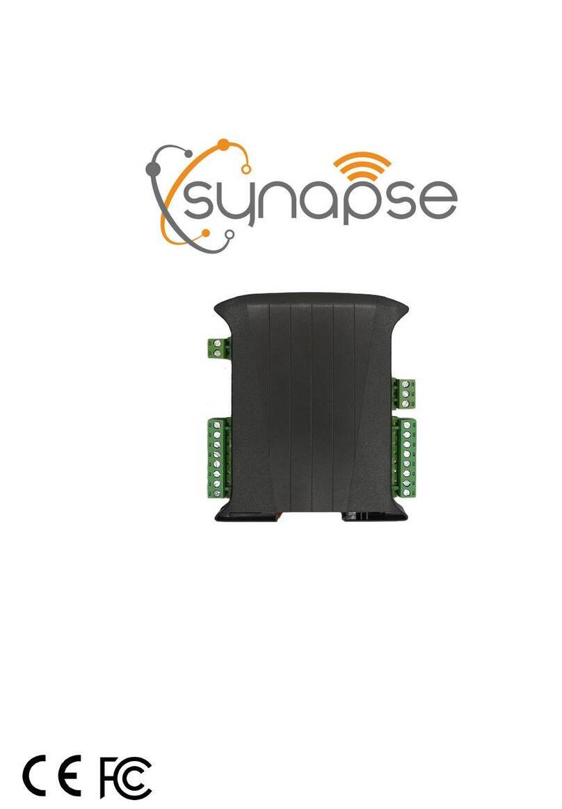
The Control-Contact provides wireless control of 120 VAC and 24VAC/VDC circuits via an on-board relay.
SPECIFICATIONS
Input power: 120VAC or 24VAC +/-10%, 50/60Hz or 24VDC +/- 10%; 3W maximum.
Dimensions: 7.1” L x 5.1” W x 4.8” H (180mm x 129mm x 122mm)
Environment: -40C to +70C, 10 to 95% RH, non-condensing
Load Power: 120VAC or 24VAC +/-10%, 50/60Hz or
24VDC +/- 10%
Load Rating: 120VAC, 13A Resistive
120VAC, 1/3HP Motor
120VAC, 1A Pilot Duty
Maximum continuous load 13A AC or DC
Surge Rating: 4KV @ 120VAC; 0.5KV @ 24VAC/VDC
Mounting: Wall or I-Beam (mounting brackets included)
Radio: 2.4 GHz (IEEE 802.15.4), +20 dBm Transmit Power, -103 Receive Sensitivity
Relay: TE part number K10P-11D15-24 (replace at your own risk)
Certifications: c(UL)us, FCC/IC, RoHS
Warranty: 1 Year
See www.synapsewireless.com/warranty for warranty terms.
WARNINGS AND CAUTIONS
•TO AVOID FIRE, SHOCK, OR DEATH; TURN OFF POWER AT CIRCUIT BREAKER OR FUSE AND TEST THAT POWER IS OFF BEFORE WIRING!
•Risk of Electric Shock - More than one disconnect switch may be required to de-energize the equipment before servicing.
•The Control-Contact must be installed in accordance with national, state, and local electrical codes and requirements.
•All work must be performed by qualified personnel.
•Use this device with copper or copper clad wire only rated 300V, 105C minimum.
•If you are unsure about any part of these instructions, consult an electrician.
For Support- Please contact your commissioning agent or installer, or open a support ticket at- https://support.synapsewireless.com/
INCLUDED MATERIAL
•Wetting Capacitor: For light dc loads of < 0.3a ,e.g. dry contact applications, the supplied wetting capacitor must be connected across the relay
terminals to avoid possible malfunction due to oxidation of the contacts. See page 5 for details.
NEEDED MATERIAL
•Screwdriver: A #2 Phillips is required to remove the cover and connect the cables to the terminals.
•Mounting: Mounting brackets are included. Mounting hole fits #10 screw
•Conduit: To maintain the IP rating of the unit, it must be installed with the PG16 cable gland with embedded o-ring supplied or with weather-proof 1/2”
conduit fittings at the power/relay connection entry point.

DOC-1000616-A-1
07/23
3
INSTALLATION INSTRUCTIONS
LOAD APPLICATION RATINGS TABLE
Please check the following chart to match the requirements for your installation and then refer to the appropriate instructions for powering the hardware
and connecting the load to be switched.
Load Power
Type of Load –Example of the load
Current (Amps) -> Other
(HP, Watts)
120VAC
Motor Load –Exhaust Fan
7.2 A -> 1/3 HP
120VAC
Resistive - Heater
13 A -> 1500 W
120VAC
Pilot Duty –Step up Relay / Contactor
1/10A -> Contactor coil VA rating
120VA sealed / 1200VA Inrush
24VAC
Resistive or Inductive - HVAC or MAU Control
2 A
24VDC
Resistive or Inductive - HVAC or MAU Control
5 A
Dry Contact Low Power Control - Robovent
control or PLC control input
If < 0.3 A - Note: must use wetting
capacitor supplied
Note: maximum of 13A continuous load
MOUNT THE CONTROL CONTACT
NOTE: For best RF performance and signal strength, do not mount this device inside a metal box.
Final installed unit should also be mounted with open space on 2 or more sides.
1. Select a suitable installation location for the Control Contact (e.g., close to the load that will be controlled)
2. Mount the Control Contact using the brackets included.
3. The installer is expected to select the correct hardware for mounting to the type of material they are working with.
CONNECTING POWER AND SWITCHED LOADS TO THE CONTROL CONTACT
NOTES:
•Disconnect all power before installation or service.
•The COM/GND terminal of the Control-Contact 24VAC/VDC power input should not be tied to earth ground.
•The Relay Circuits are separated from the power circuits once they are in the enclosure. Follow the NEC guidelines for
conductors in the conduit to get through the gland into the enclosure. To maintain a watertight connection, the cables going
through the gland must be in a single sheath.
oNEC Section 725.136(I) allows Class 2 conductors to be installed with conductors of electric light, power, and Class 1
circuits when a minimum 2‐inches of separation is maintained or if all of the Class 2 circuit conductors are in non–
metallic-sheathed cables in addition to the insulation on the conductors.
•The cable gland fits cable sizes .210” - .334” (5.3mm-8.5mm) PN: Heyco M3219GBH”
1. Open the enclosure cover and remove the metal bracket by undoing the two bottom screws. These are captive screws and will
remain attached to the bracket. See Figure 1A.
2. Feed the cable/wires through the cable gland. A 16AWG-5 conductor jacketed cable, 0.26”- 0.54” diameter, is recommended to
maintain the IP rating of the enclosure. See Figure 1B.
Figure 1A. Remove Wiring
Compartment Bracket
Figure 1B. Feed
Cable/Wires.

DOC-1000616-A-1
07/23
4
THERE ARE 3 WAYS TO POWER THE CONTROL CONTACT, SELECT THE BEST OPTION FOR YOUR APPLICATION
NOTE- The power connections are inputs ONLY and are exclusive. Do not connect AC and DC to the device.
•POWER OPTION 1: 120VAC
•POWER OPTION 2: 24VAC
•POWER OPTION 3: 24VDC
POWER OPTION 1: 120VAC
For 120VAC power: Connect the 120VAC power wires to wire terminals L (Line) and N (Neutral) and connect the earth ground wire to G (Ground).
POWER OPTION 2: 24VAC
For 24VAC power: Connect the 24VAC power wires (e.g. from an HVAC 24VAC transformer) to wire terminals 24VAC/DC and COM/GND maintaining the
correct polarity.
POWER OPTION 3: 24VDC
For 24VDC Powered: Connect the DC power supply wire (+) to 24VAC/DC and (-) to COM/GND.

DOC-1000616-A-1
07/23
5
SWITCHING LOADS- CHOOSE FROM THE FOLLOWING:
NOTE: The relay in this device does not latch. If the device loses power, connections will default to the “normal” state. The normally open terminal will
be open to common, and normally closed terminal will be closed to common. Please ensure you wire this power-loss default to the safest state
possible. Avoid mis-wiring. Pay attention to the NO and NC contacts.
120VAC Load relay Connections: Connect the Line (hot) wire to the relay wire terminal C (Common) and depending on the required Relay Logic
connect the Load wire to the NO (Normally Open) or to the NC (Normally Closed) terminal. See Figure 5. Never connect the Load to both the NO and the
NC terminals.
24VAC Load relay connections: Connect the 24VAC Live wire to the relay wire terminal C and depending on the required Relay Logic
connect the Load wire to the relay terminal NO or to the NC terminal.
24VDC Load relay connections: Connect the 24VDC (+) wire to the relay wire terminal C and depending on the required Relay Logic connect
the Load wire to the relay terminal NO or to the NC terminal.
Note: for light DC loads of < 0.3A ,e.g. dry contact
applications, the supplied wetting capacitor must be connected
across the relay terminals to avoid possible malfunction due to
oxidation of the contacts.

DOC-1000616-A-1
07/23
6
FINAL STEPS
1. Replace the wiring cover
Reinstall the metal bracket, ensure the wires are properly routed under the bracket notches and tighten the two bottom screws,
torque to 20 in-lbs.
2. Tighten the cable gland
Tighten the cable gland over the cable/wires and torque to 40-70 in-lbs, depending on the cable diameter and harness. to ensure
the enclosure is properly sealed.
3. Set the Manual Override Switch
The Manual Override Switch is a 3 position DPDT toggle switch. The switch has a 0.5” long locking lever to actuate the switch, for
safety the lever needs to be pulled to change the position of the switch.
When switched to the top position, the switch forces the relay to turn ON, it forces the relay OFF when switched to the bottom
position and the relay is in AUTO (driven by the wireless interface) when switched to the center position. The Switch should be set
for AUTO for normal operation.
4. Close and latch the enclosure cover
Check the gasket to make sure it is properly seated in the guide on the enclosure cover before latching closed. With the gasket
properly seated in the guide, close and patch the enclosure cover.
5. Configure the device
Set up a zone and schedule in SimplySnap to automatically control the attached loads.
STATUS LEDs
LED
Color
Status
NETWORK
Red
No Network Found (Communication Lost)
NETWORK
Blue
Network Found, Controller Not Configured (Not yet added to SimplySnap)
NETWORK
Green
Network Found, Controller Configured (Normal Operation)
RELAY
Orange
Relay is closed
RELAY
Off
Relay is open
AUTO
Green
Manual override switch is in the Auto position
AUTO
Off
Manual override switch is NOT in the Auto position
POWER
Blue
Power is on (normal)
POWER
Off
Power is off or has failed

DOC-1000616-A-1
07/23
7
REGULATORY INFORMATION AND CERTIFICATIONS
RF Exposure Statement: This equipment complies with FCC radiation exposure limits set forth for an uncontrolled environment.
This equipment should be installed and operated with minimum distance of 20cm between the radiator and your body. This
transmitter must not be co-
located or operating in conjunction with any other antenna or transmitter.
Industry Canada (IC) certifications: This digital apparatus does not exceed the Class B limits for radio noise emissions from
digital apparatus set out in the Radio Interference Regulations of the Canadian Department of Communications.
Le present appareil numerique n’emet pas de bruits radioelectriques depassant les limites applicable aux appareils numeriques de la
class B prescrites dans le Reglement sur le brouillage radioelectrique edicte par le ministere des Communications du Canada.
FCC certifications and regulatory information (USA only)
FCC Part 15 Class B: This device complies with part 15 of the FCC rules. Operation is subject to the following two conditions: (1)
These devices may not cause harmful interference, and (2) These devices must accept any interference received, including
interference that may cause harmful operation.
RADIO FREQUENCY INTERFERENCE (RFI) (FCC 15.105): This equipment has been tested and found to comply with the limits
for a Class B digital device, pursuant to Part 15 of the FCC rules. These limits are designed to provide reasonable protection against
harmful interference in a residential installation. This equipment generates, uses, and can radiate radio frequency energy and, if not
installed and used in accordance with the instructions, may cause harmful interference to radio communications. However, there is
no guarantee that interference will not occur in a particular installation. If this equipment does cause harmful interference to radio or
television reception, which can be determined by turning the equipment off and on, the user is encouraged to try to correct the
interference by one or more of the following measures: (1) Re-orient or relocate the receiving antenna; (2) Increase the separation
between the equipment and the receiver; (3) Connect the equipment into an outlet on a circuit different from that to which the
receiver is connected; (4) Consult the dealer or an experienced radio/TV technician for help.
Construction of control: Independently Mounted
Method of Mounting the Control: Surface Mounting
Type 1 Action, Pollution Degree: 4 / 2 (2 refers to the environment within the outdoor enclosure)
Impulse Voltage: 330V (when wired as Class 2) / 2500V (when wired as Class 1)
CERTIFICATIONS
Model : CONTROL-CNTC-101
Contains FCC ID : U9O-SM220
Contains IC : 7084A-SM220
ROHS : 3:2011/65/EU(2015/863)
UL File No :E513705
Table of contents
Other Synapse Control Unit manuals
Popular Control Unit manuals by other brands

Microchip Technology
Microchip Technology RN41 manual

Sonder
Sonder Allegro 576 Series Technical Installation & Operation Manual

Emco
Emco A1100 Assembly and installation instructions

GEM
GEM R478 Tugela operating instructions

Moxa Technologies
Moxa Technologies MiiNePort E Series Quick installation guide

HELVAR
HELVAR 458/SW8 Installation and user guide