manuals.online logo
Brands
  1. Home
  2. •
  3. Brands
  4. •
  5. Riello
  6. •
  7. Control Unit
  8. •
  9. Riello CSD 35 User manual

Riello CSD 35 User manual

HELIOTERM INVERTER
1Doc-0091338 Rev. 0
PT
Avisos preliminares
Estas instruções são parte integrante do manual do aparelho
no qual o KIT é instalado. Consulte este manual para as
ADVERTÊNCIAS GERAIS e REGRAS FUNDAMENTAIS DE SEGURANÇA.
CSD 35 - PLACA ELETRÓNICA PARA O
COMANDO NA PAREDE
Versões
Códigos
20116411
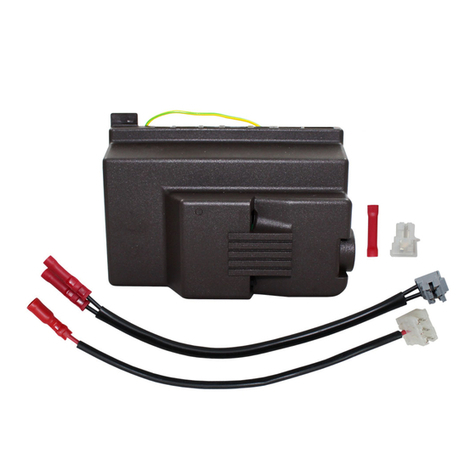
CSD 35 - Placa eletrónica para o comando na parede
Em algumas partes do manual são utilizados os símbolos:
ATENÇÃO = para ações que exigem cautela especial
e preparação adequada.
PROIBIDO = para ações que não devem
absolutamente ser executadas.
O comando possui contactos limpos independentes para
o comando de um refrigerador, de uma caldeira e de uma
entrada do contacto de presença. Se for uma versão de
2 tubos, está equipado com uma saída de 230 V para o
comando da eletroválvula de verão e inverno. Através da
sonda de temperatura da água de 10 kΩposicionada na
cavidade presente na bateria, o aparelho pode gerir as
funções de temperatura mínima da água no aquecimento
(30 °C) e máxima no arrefecimento (20 °C). A placa prevê
também o funcionamento sem sonda H2, nesse caso, os
limites de paragem do ventilador são ignorados.
Montagem, conguração e ligações dos
painéis de comando a bordo da máquina
EN
Preliminary instructions
This instruction booklet is an integral part of the manual
of the device on which you install the kit. In that manual,
please refer to the WARNINGS and the BASIC SAFETY RULES.
CSD 35 - ELECTRONIC BOARD FOR WALL
CONTROL
Versions
Codes
20116411
CSD 35 - Electronic board for wall control
The following symbols are used in this publication:
WARNING = actions requiring special care and
appropriate training.
DO NOT = actions that MUST ON NO ACCOUNT be
carried out.
The control have independent free contacts to control
a chiller and a boiler and a presence input. The 2-pipe
versions have a 230 V output for powering the summer
and winter solenoid valve while. The water temperature
probe (10KΩ) located in the well on the battery manages
the minimum in heating (30°C) and maximum in cooling
(20°C) functions.
The board can also operate without a water probe, case in
which the fan stop thresholds will be ignored.
Mounting, setting and connection of on-
board machine control panels
HELIOTERM INVERTER
2
A
D
E
C
H
I
L
B
G
M
Doc-0091338 Rev. 0
PT
ligue o engate rápido do Motor (MOTOR) ao presente na
placa (ref.I) *;
no par de terminais GRID (ref.L) está presente uma ponte
que assegura o funcionamento das versões Design Inverter
e Design Inverter Plus sem microinterruptor. Para as
outras versões, remova a ponte e ligue os dois terminais
provenientes do microinterruptor de segurança da grelha*.
ligue o conector da sonda de água ao conector H2)presente
no aparelho. A sonda de temperatura da água controla a
temperatura dentro das baterias e determina o arranque do
ventilador com base nos parâmetros predenidos (funções
de temperatura mínima de inverno e de temperatura
máxima de verão). Verique se está corretamente inserida
na cavidade presente na bateria**.
efetue as ligações elétricas (
consulte também o parágrafo
“Montagem da sonda de temperatura do ar”
), organize
as cablagens, xe os cabos com ajuda das 3 forquilhas
fornecidas (ref.G);
feche a caixa, xando os 4 parafusos (ref.H);
volte a montar o painel lateral estético do aparelho;
aperte o parafuso superior no painel de controlo;
coloque as tampas dos parafusos no respetivo alojamento
no painel de controlo;
* Para versões com ligações hidráulicas à direita, consulte o
respetivo parágrafo.
**O regulador funciona mesmo sem a sonda de água ligada.
Insira o painel de controlo na respetiva sede, na parte
superior do aparelho e xe-o com os dois parafusos
fornecidos (ref.A).
Para instalar a caixa das ligações:
abra a caixa (ref.B);
insira o dente inferior na respetiva ranhura (ref.C), na
parte lateral do aparelho;
encaixe a parte superior da caixa na parte lateral (D);
xe-a com os dois parafusos fornecidos (ref.E);
xe o cabo de terra à estrutura do ventiloconvector/
ventiloradiador, utilizando o parafuso fornecido (deve
ser aplicada uma força mínima de aberto de cerca de
2N);
Montagem
EN
the 2 terminals of the GRID clamp (ref. L) feature a jumper
that ensures the operation of the Design Inverter and
Design Inverter Plus versions without microswitch. For
the other versions remove the jumper and connect the
two terminals from the grid safety microswitch*.
connect the water probe connector H2 on the Cooler-
convector/cooler-radiator; the water temperature
probe checks the temperature inside the batteries
and determines the start of the fan based on the set
parameters (minimum winter and maximum summer
functions). Check that it is inserted correctly in the well
on the battery**.
make the electrical connections (see also section
“Mounting air temperature sensor”), order the wiring
and x the wires using the 3 supplied clamps (ref. G);
close the box and x with the 4 screws (ref. H);
mount the aesthetic side panel on the Cooler-convector/
cooler-radiator;
tighten the upper screw on the control panel;
place the screw cover into the slot on blind panel;
* For versions with hydraulic connections on the right
refer to the relevant paragraph.
**The regulator can also work without the water probe.
Place the control panel into its housing in the upper part
of the cooler-convector/cooler-radiator and x it with the
two supplied screws (ref. A).
To install the connection box:
open the box (ref. B);
insert the lower lug into the special slot (ref. C) on the
side of the appliance;
hook the upper part of the box to the side (ref. D);
x it with the two supplied screws (ref. E);
x the earth wire to the cooler-convector/cooler-radiator
structure using the supplied screws (the minimum force
of about 2N must be used when screwing-up);
connect the rapid connector on the motor (MOTOR) to
that on the board (ref. I) *;
Mounting
HELIOTERM INVERTER
3
E
C
B
N
EV1
N
EV2
BA
ON
D
C
H4 H2 AIR
COMM
ASCII
RTU
MOTOR
LN
GRIDGRIDCP
CHILLER BOILER
LED
AD
BA
ON
D
C
Doc-0091338 Rev. 0
PT
Na placa eletrónica do comando, estão posicionados dois
dip-switches para a conguração do funcionamento do
aparelho de acordo com as necessidades.
Através do cursor C, é possível modicar a lógica de
funcionamento noturno no aquecimento: na posição ON
a ventilação é inibida, permitindo, assim, que a máquina
aqueça os ambientes por irradiação e convecção natural,
tal como acontece nos radiadores tradicionais. Na posição
OFF, pelo contrário, o ventilador funciona normalmente.
Ao colocar o cursor B em ON é ativada, apenas no
arrefecimento, a ventilação contínua na velocidade
mínima mesmo após o setpoint ser atingido, para permitir
um funcionamento mais regular da sonda de temperatura
e evitar a estraticação do ar. Com o cursor na posição OFF,
a função é repetida (2 minutos em ON, 10 minutos em OFF).
Conguração das funções auxiliares dip-
switch B e C
Quando o contacto ligado à entrada CP (ref.D) é fechado,
todos os serviços são desligados.
Se o contacto estiver aberto, a unidade está ativa, se o
contacto estiver fechado, a unidade está desativada e
quando uma tecla é premida, o símbolo pisca.
Não é possível ligar a entrada em paralelo à de outras
placas eletrónicas (utilize contactos separados).
When the contact connected to the CP (ref. D) input is
closed all the users connected will be switched off.
If the contact is open the unit is active, if the contact is
closed the unit is deactivated an by pressing a key the
symbol ashes.
The input cannot be connected in parallel to one of
another electronic board (use separate contacts).
EN
There are two dip-switches on the electronic control panel
for setting the functions of the appliance as required.
Use cursor C to modify the night function logic: In the
ON position the air ow is inhibited thus letting the
machine heat the room through natural radiation or
convection as happens with traditional radiators; in the
OFF position the fan functions normally.
Set cursor B to ON (in cooling only) to enable the
continual air ow at the minimum speed, even after the
set point has been reached to ensure a more regular
functioning of the temperature probe and to prevent air
stratication. Setting the cursor on OFF the function is
cycled (2 minutes ON, 10 minutes OFF).
Setting auxiliary functions dip-switches B
and C
Ligações de entrada do contacto de presença CP CP presence contact input connection
Conguração da função de velocidade
máxima de ventilação de ar
Setting maximum fan speed function
O microinterruptor A está congurado em OFF: a função de
velocidade máxima é às 1400 rpm (modo Confort). Altere a
conguração para ON, se pretender a função de velocidade
máxima às 1700 rpm (modo Performance).
Dip switch A is in OFF position: maximum fan speed
function at 1400 rpm (Confort mode). Change position to
ON if you want maximum fan speed function at 1700 rpm
(Performance mode).
The cursor D OFF position selects operation for 2 pipes
systems. You cannot change this setting.
O cursor D na posição OFF seleciona o funcionamento
para instalações com 2 tubos. Esta conguração não
pode ser alterada.
HELIOTERM INVERTER
4
B
C
D
A
Vista dal basso / Bottom view
Doc-0091338 Rev. 0
PT
Ligações
-AB+ ligação serial para o comando remoto de parede CPD
35 (respeite a polarização A-B)
H2**sonda de temperatura da água (10KΩ)
H4 não disponível
M1 motor do ventilador DC inverter
S1 microinterruptor de segurança da grelha
Y1 eletroválvula de água (tensão de saída de 230 V/ 50 Hz 1 A)
Y2 ap móvel (tensão de saída de 230 V/50 Hz 1 A)
L-N ligação de alimentação elétrica 230 V/50 Hz
BO saída de permissão da caldeira (contacto limpo máx. 1 A)
CH saída de permissão do refrigerador (contacto limpo
máx. 1 A)
CP entrada do sensor de presença (se estiver fechado, o
ventiloconvector é colocado em stand-by.)
AIR Sonda de ar opcional (*)
RS Cablagem da versão Plus (ligação a efetuar pelo
instalador)
HRS sonda de água, versão Plus (2kΩ)
* Em alternativa, ligue à sonda de ar do controlo de parede
CPD 35.
** Se, após a ligação, a placa detetar a sonda, o arranque
ocorre em condições normais com funções de
temperatura mínima da água no aquecimento (30 °C) e
máxima no arrefecimento (20 °C). A placa prevê também
o funcionamento sem sonda, nesse caso, os limites de
mínimo e máximo são ignorados.
Montagem da sonda de temperatura do ar Mounting air temperature probe
- Para posicionar a sonda de temperatura (ref.A)
- passe a sonda através do furo do ombro (ref.B)
- insira a sonda no furo inferior (ref.C)
- xe a sonda no respetivo engate (ref.D)
- To position the temperature probe (ref. A)
- pass the probe through the hole on the shoulder (ref. B)
- insert the probe in the lower hole (ref. C)
- x the probe in the special hook (ref. D)
EN
Connections
-AB+ Serial connection for wall-mounted remote control
CPD 35 (respect the A-B polarisation)
H2 water temperature probe (10KΩ)
H4 not available
M1 fan motor DC inverter
S1 grill safety micro-switch
Y1 water solenoid valve (230V/50Hz 1A powered output)
Y2 mobile ap (230V/50Hz 1A powered output)
L-N 230V/50Hz electrical power supply connection
BO boiler go-ahead output (free contact max 1A)
CH chiller go-ahead output (free contact max 1A)
CP presence sensor input (if closed, the fan coil goes into
stand-by.)
AIR Optional air probe (*)
RS Plus version wiring (to be connnected by the installer)
HRS Plus version probe (2kΩ)
* Connect as an alternative to the air probe of the CPD 35
wall-mounted control panel
** If after powering the equipment the board detects
the probe, the start-up will take place under normal
conditions with minimum water temperature in heating
(30 °C) and maximum water temperature in cooling (20
°C) functions. The board can also operate without a
water probe, case in which the fan stop thresholds will
be ignored
HELIOTERM INVERTER
5
8mm0.2-1.5mm2
A
Per scollegare i cavi premere con un
cacciavite sul corrispondente dentino
bianco (rif.A) ed estrarre il conduttore
Doc-0091338 Rev. 0
PT
Os 4 terminais de mola (ref.A) para a ligação do controlo
de parede CPD 35 aceitam cabos rígidos e exíveis com
secção de 0,2 a 1,5 mm² (0,75 mm² se forem ligados 2
condutores no mesmo terminal), ao passo que se os
mesmos possuírem ponteiras terminais com abraçadeira
de plástico, a secção máxima é de 0,75 mm².
Efetue uma esfoladura de 8 mm de comprimento, se o cabo
for rígido, pode ser inserido facilmente, se for exível, é
preferível utilizar um alicate de bico.
Empurre os cabos até ao fundo e verique se estão xados
corretamente, puxando-os ligeiramente.
The 4 spring terminals (ref. A) intended for the connection
of the CPD 35 wall-mounted control panel are compatible
with 0.2 to 1.5 mm² section (0.75 mm² if connecting 2
conductors to the same terminal) rigid or exible cables,
while if they are provided with lugs with plastic collar,
their maximum section should be of 0.75 mm².
Strip the cable by 8 mm and then if the cable is rigid you
should be able to insert it easily while if it is exible you
will need to use some nose pliers.
Insert the cables completely and make sure they are
properly xed by pulling them slightly.
EN
HELIOTERM INVERTER
6
A
Doc-0091338 Rev. 0
PT
A placa eletrónica para remotização permite controlar
todas as funções do ventiloconvector através do comando
remoto de parede CPD 35.
É possível ligar até um máximo de 30 ventiloconvectores
a um comando remoto, comandados em broadcast (com
comandos simultâneos a todos os ventiloconvectores).
A placa possui um LED verde que indica o estado de
funcionamento e eventuais anomalias e pode ser instalada
em todas as versões.
Os principais parâmetros operacionais, o setpoint e a
temperatura ambiente, são transmitidos pelo comando
remoto de parede CPD 35 a todos os terminais ligados em
rede, permitindo um funcionamento homogéneo.
Para a utilização os ventiloconvectores, consulte as
instruções deste comando.
Através da sonda de temperatura da água de 10 kΩ
colocada na bateria, o aparelho pode gerir as funções de
temperatura mínima da água no aquecimento (30 °C) e
máxima no arrefecimento (20 °C).
Descrição
Ligação na versão Plus Connections Plus version
Nesta versão, os servomecanismos responsáveis pela
movimentação da grelha estão pré-instalados no aparelho.
Através de um conector especíco (ref. A), é possível ligá-los
à saída Y2 dos painéis.
In this version the servomechanism for moving the grid
are precable on the unit. Via a special connector (ref. A)
you can connect the output Y2 of the panels.
EN
The electronic board for remote controlling allows control
of all fan coil functions by the CPD 35 wall remote control.
It is possible to connect up to a maximum of 30 fan coils
to a remote control, which will be controlled through
broadcasting (with simultaneous commands to all fan
coils).
It can be installed on all versions; the board has a green
LED indicating the status and any faults.
The main operating parameters, the setpoint and the
room temperature are transmitted from the wall-mounted
remote control panel CPD 35 to all connected terminals in
the network, ensuring smooth operation.
For cooler-radiators use please refer to the instructions of
this control panel.
The 10 kΩwater temperature probe located in the device
battery can manage the minimum in heating (30 °C) and
maximum in cooling (20 °C) functions.
Description
A
HELIOTERM INVERTER
7Doc-0091338 Rev. 0
Sinalização dos leds (ref.A)
Led verde: sinaliza o funcionamento do
aparelho. Em caso de anomalias, pisca.
Led apagado: aparelho parado ou sem
alimentação elétrica.
Green Led: Signals the functioning of the
device. Flashes in case off faults.
Led off: device stopped or not powered.
Sinalizações de erro Error signals
Erro Ecrã
Erro de comunicação. A placa
prevê uma troca contínua de
informações na linha serial com
o controlo de parede CPD 35. Se
estas falharem durante mais de
5 minutos, é exibido o erro e o
aparelho desliga-se.
6 intermitências +
pausa
Problemas no motor do ventilador
(por exemplo, bloqueio devido a
corpos estranhos, avaria no sensor
de rotação).
2 intermitências +
pausa
Avaria na sonda de deteção da
temperatura da água (H2).
Neste caso, certique-se de que a
sonda instalada é de 10 kΩ.
3 intermitências +
pausa
Acionamento do microinterruptor
da grelha S1 devido à operação de
limpeza do ltro
intermitência
contínua de alta
frequência
Solicitação de água detetada pela
sonda H2 não satisfeita (superior
a 20 °C no modo de arrefecimento,
inferior a 30 °C no modo de
aquecimento). O ventilador para
até que a temperatura atinja um
valor adequado para satisfazer a
solicitação.
1 intermitência +
pausa
Errore Display
Communication error: The board is
provided with a function that allows
continuous information exchange
on the serial line with the wall-
mounted control panel ECA649. If it
is missing for more than 5 minutes
the relative error is displayed and
the device is deactivated.
6 ashes + pause
Fan motor fault (for example
jamming due to foreign bodies or
fault in the rotation sensor).
2 ashes + pause
Water temperature probe failure
for 2-pipe versions (H2).
In this case make sure the probe
has 10 kΩ.
3 ashes + pause
Operation of the S1 grill microswitch
due to lter cleaning
Continuous high
frequency ashing
Unmet water request detected by
H2 probe (over 20 °C in cooling,
below 30 °C in heating). The fan
will stop until the temperature
reaches an appropriate value to
meet the request*.
1 ashes + pause
* Se, após a ligação, a placa detetar a sonda de água, o
arranque ocorre com limites de mínimo e de máximo da
temperatura da água.
A placa prevê também o funcionamento sem sonda, nesse
caso, os limites de paragem do ventilador são ignorados.
* If after powering the equipment the board detects the
water probe, the start-up will take place with minimum
and maximum water temperature thresholds.
The board can also operate without a probe, case in which
the fan stop thresholds will be ignored.
LED signals (ref. A)
HELIOTERM INVERTER
8
C
DE
RIELLO S.p.A. - 37045 Legnago (VR)
tel. +39 0442 630111 - fax +39 0442 22378
www.riello.it
Doc-0091338 Rev. 0
Se for necessário inverter a posição das ligações hidráulicas
da bateria do lado esquerdo para o lado direito do aparelho,
a caixa das ligações elétricas também é invertida, mas como
o motor do ventilador e o microinterruptor de segurança da
grelha estão vinculados na posição original, é necessário
utilizar o kit especíco 20069415 disponível como acessório.
O cabo, equipado com conectores macho/fêmea, deve ser
ligado do lado direito do motor e do lado esquerdo do
engate rápido do motor presente na placa (ref.D).
Além disso, os dois terminais provenientes do
microinterruptor de segurança da grelha devem ser
estendidos e ligados do lado esquerdo do contacto GRID
presente na placa (ref.E).
Os cabos devem ser introduzidos, na parte traseira do
aparelho, no furo especíco (ref. C).
Ligação do motor nas versões com ligações
hidráulicas à direita
Sendo a nossa empresa orientada por uma política de melhoria contínua de toda a produção, as características
estéticas e dimensionais, dados técnicos, equipamentos e acessórios são suscetíveis de variação.
In the event one needs to invert the position of the hydraulic
battery connections from the left side to the right side of
the device, the electric connections box is also inverted,
but since the fan motor and the grid safety microswitch
are constrained in the original position, one must use the
special kit 20069415, available as an accessory.
The cable, equipped with male/female connectors, must
be connected on the right side to the motor and on the
left side to the quick connector of the motor present on
the board (ref.D).
Also, the two terminals from the grid safety microswitch
must be extended and connected on the left side to
contact GRID present on the board (ref.E).
The cables are fed through the back of the device through
the specic hole (ref.C).
Water connection on the right side versions
motor connection
As the manufacturer is constantly improving its products, the aesthetic or dimensional features, the technical data,
the equipment and accessories indicated could be subject to variations.

This manual suits for next models

1

Other Riello Control Unit manuals

Riello 530SE/C24V Quick start guide

Riello

Riello 530SE/C24V Quick start guide

Riello ATRB 120 N User manual

Riello

Riello ATRB 120 N User manual

Riello RMG 8862 A2 Quick start guide

Riello

Riello RMG 8862 A2 Quick start guide

Riello MO550 User manual

Riello

Riello MO550 User manual

Riello MODULO 25 DIR User manual

Riello

Riello MODULO 25 DIR User manual

Riello MG569-BWZG Quick start guide

Riello

Riello MG569-BWZG Quick start guide

Riello SC SUN 300 User manual

Riello

Riello SC SUN 300 User manual

Riello MG569 User manual

Riello

Riello MG569 User manual

Riello CSD 35 User manual

Riello

Riello CSD 35 User manual

Riello Cardin T624 User manual

Riello

Riello Cardin T624 User manual

Popular Control Unit manuals by other brands

Amit AMR-OP70C Series Operation manual

Amit

Amit AMR-OP70C Series Operation manual

Festo Pneumatic VUV operating instructions

Festo Pneumatic

Festo Pneumatic VUV operating instructions

Moeller XIOC AWB2725-1452GB Hardware and engineering

Moeller

Moeller XIOC AWB2725-1452GB Hardware and engineering

Time Electronics 7085A user manual

Time Electronics

Time Electronics 7085A user manual

Franklin Fueling Systems Healy 8701VV manual

Franklin Fueling Systems

Franklin Fueling Systems Healy 8701VV manual

Fujitsu UTW-SCBYA Installation and operating manual

Fujitsu

Fujitsu UTW-SCBYA Installation and operating manual

Samson BR 26l operating instructions

Samson

Samson BR 26l operating instructions

Televes T.OX 563822 Quick installation guide

Televes

Televes T.OX 563822 Quick installation guide

Advantech SOM 144 Design specification

Advantech

Advantech SOM 144 Design specification

AVG WATTS manual

AVG

AVG WATTS manual

Aerotech ARMS Series Hardware manual

Aerotech

Aerotech ARMS Series Hardware manual

Coniu Go GSM Scout Series manual

Coniu Go

Coniu Go GSM Scout Series manual

Texas Instruments ADC1173 user guide

Texas Instruments

Texas Instruments ADC1173 user guide

Hasco H1250 Series operating instructions

Hasco

Hasco H1250 Series operating instructions

High-Flying HF-LPC100 user manual

High-Flying

High-Flying HF-LPC100 user manual

GEM D480 Victoria Installation, operating and maintenance instructions

GEM

GEM D480 Victoria Installation, operating and maintenance instructions

Sel SEL-2600 instruction manual

Sel

Sel SEL-2600 instruction manual

rtd DM35424HR user manual

rtd

rtd DM35424HR user manual

manuals.online logo
manuals.online logoBrands
  • About & Mission
  • Contact us
  • Privacy Policy
  • Terms and Conditions

Copyright 2025 Manuals.Online. All Rights Reserved.