Important
The motor and power cables must be twisted for EMC reasons.
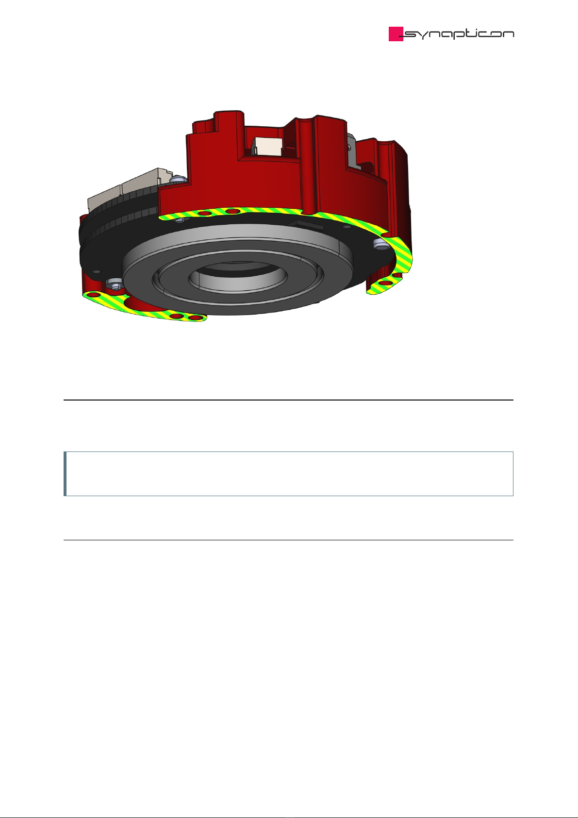
Note
SOMANET servo drives are densely packed with high-performance components. Even at idle/torque
off, several components such as power supplies, cause the servo drive to get warm, especially when
it’s not connected to any heat conducting structure. The servo drives’ power stages and control
algorithms were optimized for efficiency at high power output and actually make them one of the
most efficient servo drives available. The heat generation is not linear, which makes it actually more
noticable at idle or low power. Please ensure by design of your mounting situation that the heat
interface is connected to sufficient structure to appropriately dissipate generated heat.
Note
Use a protected extra-low voltage (PELV) power supply.
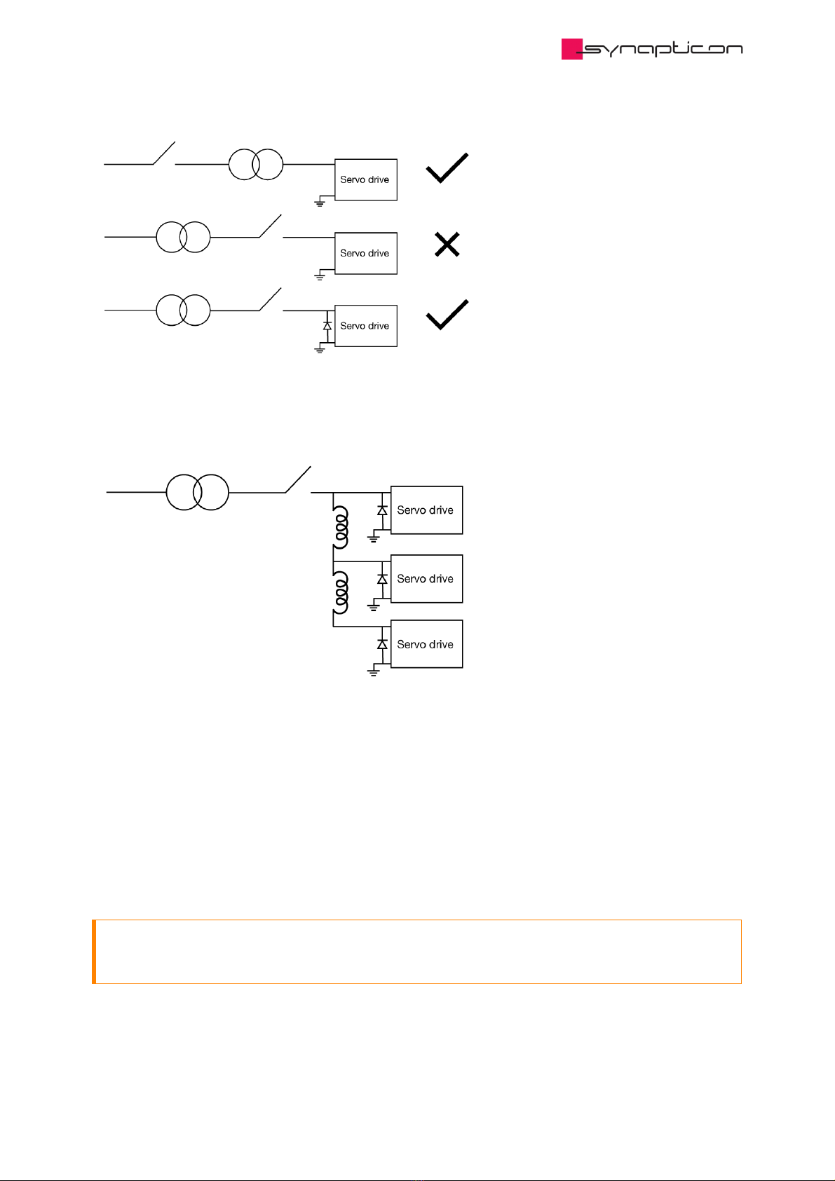
1.1.1.1 Warning about using contactors behind the power supply
Attention
Our servo drives are designed for voltages between 24 V and 48 V (60 V Max), they should be run with
an appropriate extra-low voltage supply. Please do not use contactors behind the power supply
since the transient-voltage-suppression diodes could get damaged due to the power-up voltage
increase (Surge). This is likely to happen when the power up occurs fast and can lead to complete
failure of your servo drive.
If contactors behind the power supply are used, it’s necessary to include an uni-directional TVS
diode type 1.5KE62A-E3/54* between Main Power Supply and Ground of the terminal.
* this model has been successfully tested by Synapticon. Other products with the same specifications
may also be appropriate but can’t be recommended.


