www.lynxnet.co.nz
OVERVIEW
General Description
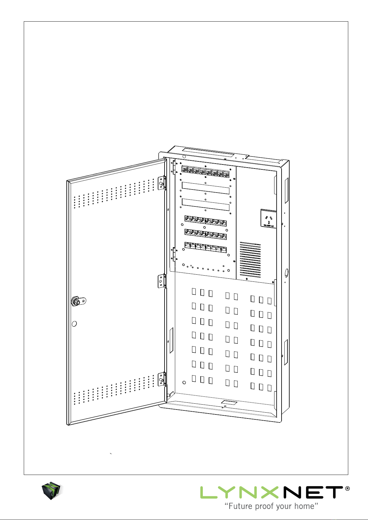
The LN-2400 DH is an “All in One” distribution hub
designed to be installed during the construction or
renovation of a home or small office. The system is
Fibre Optic Ready and is CAT6 rated.
Installation of the panel will help “Future Proof”
your home or office through the flexible distribution
of:
• Telephone Outlets
• UHF Antenna Signals
• Computer Network
• Internet Connections
• Remote Control Repeaters
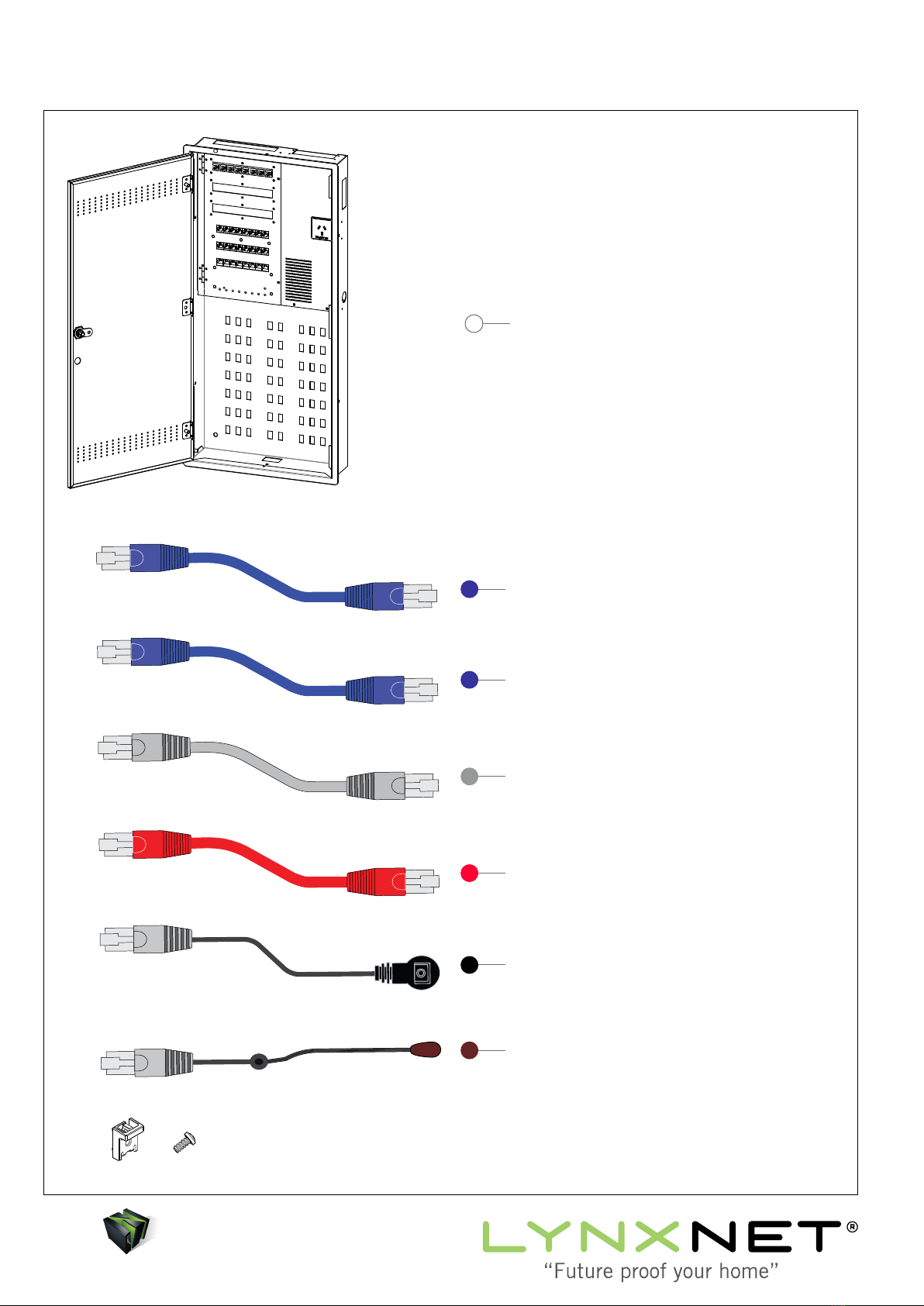
The system comes completely assembled and
configured to minimise installation time and allow
for quick, easy and flexible distribution to up to 24
room outlets within your home or office.
Features of this innovative Distribution Hub include:
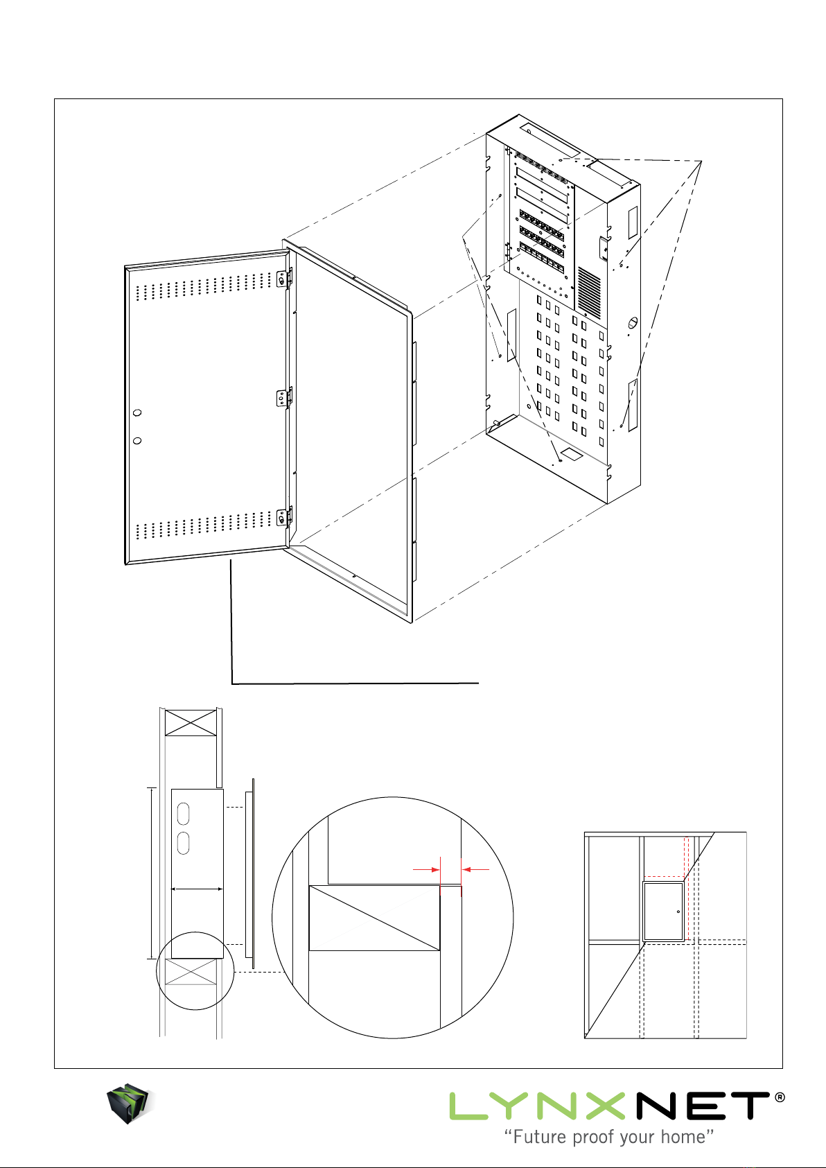
• Easy Installation & Configuration
• 8 x Room Outlets (Add up to 16 Outlets if required)
• 8 x Telephone Outlets
• 6 x IR Repeater Ports
• 8 Port Network Hub
• Free-View Distribution
• 1 x TV Splitter (1 x UHF Input / 4 Outputs)
• DSL Modem Port Including Filter
• 12 x CAT6 Patch Leads Included
Antenna Distribution
An on board TV Spliter provides one dedicated input
for UHF and 4 output signals to any of your room
outlets.
Computer Network
An onboard 1Gb Ethernet Switch provides
distribution for an 8 port computer network.
Port 1 is used as an input from the DSL Modem,
while ports 2-8 may be patched to any one of up to
24 room outlets using the blue patch leads.
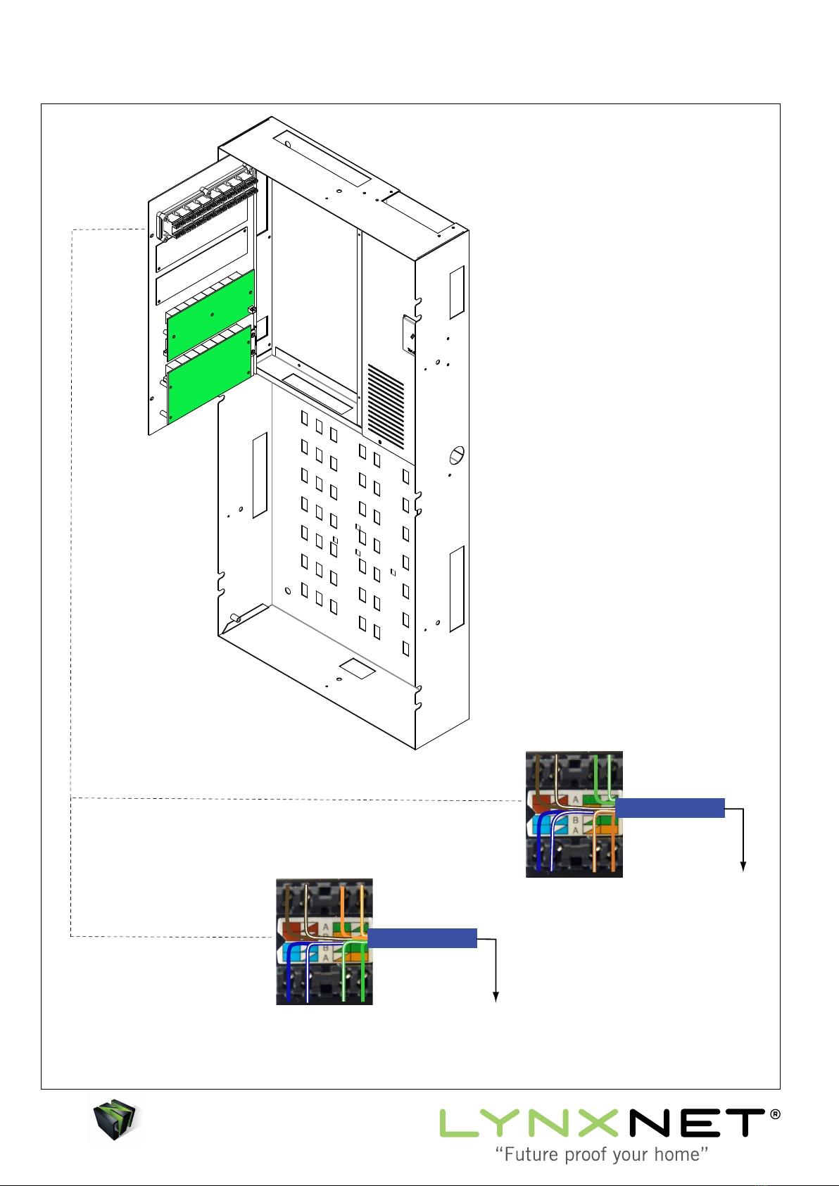
Telephone Distribution
The LN-2400 DH allows for 2 incoming lines. Line
1 and 2 are punched down on the rear of the patch
panel.
Termination is also provided to allow the main
Telephone line to go via a monitored Alarm panel.
An onboard DSL filter provides filtered signal to
the 8 Telephone ports on the front of the patch
panel. These 8 Telephone ports can be patched to
any one of up to 24 room outlets using the grey
patch leads.
Line 2 (if connected) has 1 port on the front of the
patch panel which can be patched to any one of up
to 24 room outlets using a grey patch lead.
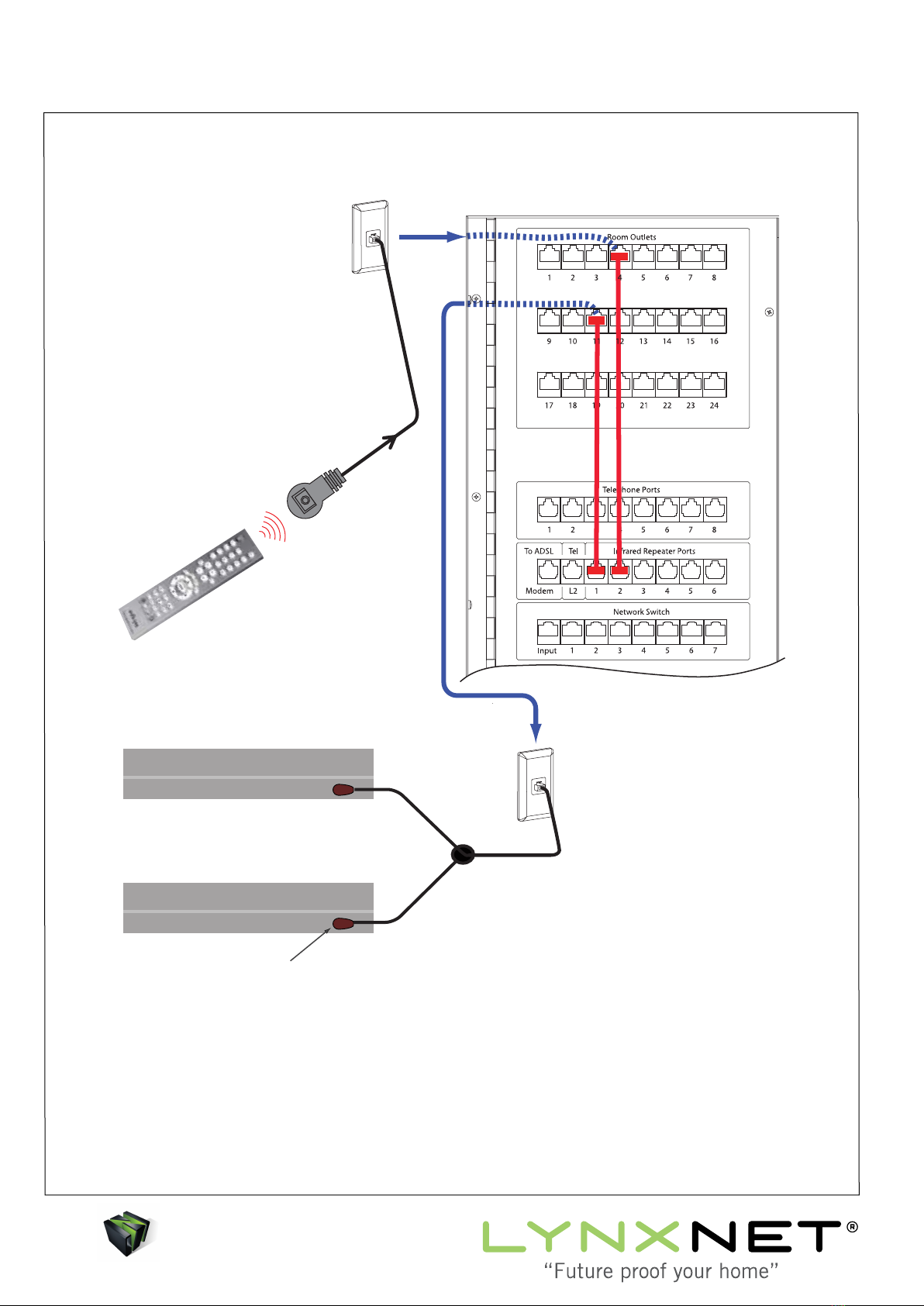
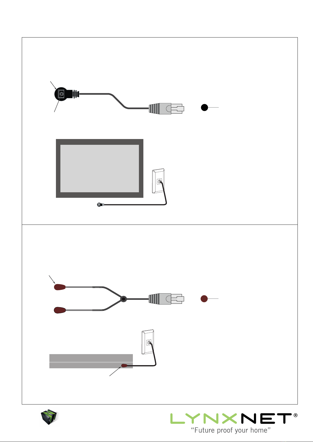
IR Distribution
The LN-2400 DH provides onboard circuitry to
receive and distribute infra-red remote control
signals via the 6 IR ports on the front of the patch
panel, which can be patched to any one of up to 24
room outlets using the red patch leads.
Multiple IR receivers can be used to send IR signals
to one or more products.
3