manuals.online logo
Brands
  1. Home
  2. •
  3. Brands
  4. •
  5. Synthesizers.com
  6. •
  7. Commercial Food Equipment
  8. •
  9. Synthesizers.com Q130 User manual

Synthesizers.com Q130 User manual

Q130 Rectifier/Clipper
Aug 2014
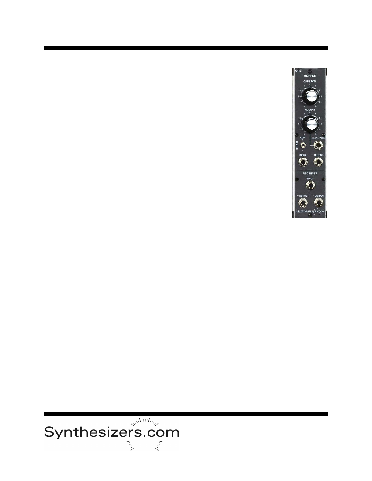
The Q130 Module provides both a signal rectifier and a voltage controlled clipper.
These functions have the effect of changing a waveform and its harmonic content or
simply changing a control signal for use by another module.
The Clipper section of the module is used to clip off the top, bottom, or both of a
waveform. The level at which the clip occurs can be set manually with the front panel
control knob or set with a voltage control signal from another module. The amount of
effect that the voltage control signal has can also be adjusted.
The Rectifier section simply takes an input and rectifies it. This has the effect of dou-
bling the frequency of a sine wave, while turning a sawtooth wave into a triangle
wave with the same frequency. Both positive and negative sides are available simul-
taneously.
Patch the two sections together to create completely new types of waveforms.
Specifications
Panel Size: Single width 2.125"w x 8.75"h.
Input Signals: 10V PP, DC to 20khz
Control Frequency: 1khz maximum
Power: +15V@15ma, -15V@15ma
Controls and Connections
Clipper Section
Clip Level Control
Manually sets the voltage at which clipping will occur. 0-15 volts.
This level is mixed with the voltage control level input jack.
Amount Control
Manually sets the amount of effect that the clip level input jack signal provides.
Input Jack
Input signal.
Output Jack
Clipped output signal.
Clip Level Jack
Input to set the clipping level. Mixed with the manual control.
Clip Switch
Determines which side of the waveform is clipped: +, -, or both.
Rectifier Section
Input Jack
Input signal.
+ Output Jack
Rectified output signal.
- Output Jack
Inverted rectified output signal.
Q130 Rectifier/Clipper
Aug 2014
Manually set
clipping level
Inverted version of
rectified output
Sets the amount of
voltage-control
on clip level
Sets which section of the
waveform is clipped
Input to be clipped
Voltage control
of clipping level
Clipped output
Signal to be rectified
Rectified output
Q130 Rectifier/Clipper
Aug 2014
Usage and Patch Tips
The clipper section can be used to limit the amplitude of a signal and to create
unusual sounds by adding harmonic content through changing of the wave-
form. Clipping levels can be controlled with an oscillator or envelope generator
to create interesting effects.
It’s important to remember that the clip level control and the clip input jacks are
mixed together to create a clipping voltage. The ‘amount’ control attenuates
the clip level input voltage from its full level down to zero depending on the
knob’s position. Viewing the results with an oscilloscope will help you under-
stand the function and interaction of these controls.
The rectifier has the effect of taking the bottom of the waveform (the part below
0 volts) and flipping it to the top. When a sawtooth or ramp wave is used as an
input, the output will become a triangle wave at 1/2 the frequency which is level
shifted. When a triangle waveform is used as the input, the output will be trian-
gle at twice the frequency. When a sine waveform is used as the input, the
output will be a waveform with unusual harmonic content at twice the fre-
quency. When a square or pulse waveform is used as the input, the output will
be only be a small spike which has minimal usage.
Patching the output of the clipper into the input of the rectifier can create a
whole new group of waveforms in which every other cycle is clipped.
Waveforms
Q130 Rectifier/Clipper
Aug 2014
Calibration and Testing
No calibration is required for this module.
Clipper section
1. Move the clip switch to the ‘both’ position (middle).
2. Place a 1khz 10v PP triangle waveform into the clipper input jack.
3. Use an oscilloscope to verify that the waveform becomes clipped at both the
top and the bottom as the clip level control is turned. At the full counter-
clockwise position, the signal will be off.
4. Change the clip switch to both + and – and verify that only the top or bottom
of the waveform is clipped.
5. Set the clip level control full counter-clockwise, clip switch to ’both’, amount
control to full clockwise and place a 1 volt signal into the clip level jack. Verify
that the waveform is clipped at 1 volt.
Rectifier Section
1. Place a 1khz 10v PP sine waveform into the rectifier input jack.
2. Use an oscilloscope to verify that the waveform is rectified at the outputs
with the expected polarities.
Power Connector
6 pin .1” MTA type connector made
by AMP. Available from Mouser
Electronics or Digi-Key. Modules
have a male PCB mount connector
and cable harnesses have a female.
Part Numbers:
Female cable mount: #6404416
Male PCB mount: #6404566
Pinout:
1 = +15v
2 = key (pin removed)
3 = +5v
4 = gnd
5 = -15v
Not all voltages are used on all mod-
ules.
PCB Layout

Popular Commercial Food Equipment manuals by other brands

Costco 5P-08WT manual

Costco

Costco 5P-08WT manual

Beper BT.651Y manual

Beper

Beper BT.651Y manual

Blue Seal EF30 Installation & operation manual

Blue Seal

Blue Seal EF30 Installation & operation manual

Tecfrigo Snelle 400 GS installation instructions

Tecfrigo

Tecfrigo Snelle 400 GS installation instructions

Follett PFT Series Operation and maintenance manual

Follett

Follett PFT Series Operation and maintenance manual

MEFE CAT 206 PTR User manual and maintenance

MEFE

MEFE CAT 206 PTR User manual and maintenance

Diamond AL1TB/H2-R2 Installation, Operating and Maintenance Instruction

Diamond

Diamond AL1TB/H2-R2 Installation, Operating and Maintenance Instruction

Salva IVERPAN FC-18 User instructions

Salva

Salva IVERPAN FC-18 User instructions

Allure Melanger JR6t Operator's manual

Allure

Allure Melanger JR6t Operator's manual

saro FKT 935 operating instructions

saro

saro FKT 935 operating instructions

Hussmann Rear Roll-in Dairy Installation & operation manual

Hussmann

Hussmann Rear Roll-in Dairy Installation & operation manual

Cornelius IDC PRO 255 Service manual

Cornelius

Cornelius IDC PRO 255 Service manual

Moduline HSH E Series Service manual

Moduline

Moduline HSH E Series Service manual

MINERVA OMEGA DERBY 270 operating instructions

MINERVA OMEGA

MINERVA OMEGA DERBY 270 operating instructions

Diamond OPTIMA 700 Installation, use and maintenance instructions

Diamond

Diamond OPTIMA 700 Installation, use and maintenance instructions

Diamond G9/PLCA4 operating instructions

Diamond

Diamond G9/PLCA4 operating instructions

Cuppone BERNINI BRN 280 Installation

Cuppone

Cuppone BERNINI BRN 280 Installation

Arneg Atlanta Direction for Installation and Use

Arneg

Arneg Atlanta Direction for Installation and Use

manuals.online logo
manuals.online logoBrands
  • About & Mission
  • Contact us
  • Privacy Policy
  • Terms and Conditions

Copyright 2025 Manuals.Online. All Rights Reserved.