2
Field of application
The connectionCenter 3228 All-in-one is used as the basis
for refillable cartridges.
It supplies either softened, fully demineralised or deminera-
lised water with pH value stabilisation for heating systems
in accordance with VDI Guideline 2035 Part 1 and protects
heating systems against lime deposits.
It is also used to automate the filling process in hot water
heating systems.
The built-in BA backflow preventer according to DIN EN 1717
prevents the heating water from flowing back into the drin-
king water pipe.
In this combination, the direct fixed connection of drinking
water to the heating system is approved according to DIN
EN 1717.
The integrated pressure reducer ensures the correct and
constant pressure of the system.
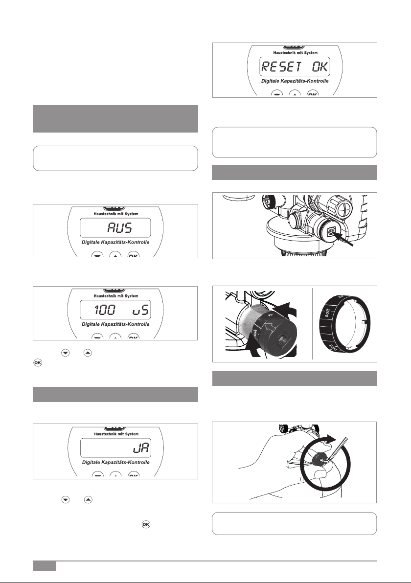
Design
The Connection Center All-in-one contains a digital capacity
control, a shut-off valve on the inlet and outlet side, a sam-
pling connection for soft water, a hardness measuring set, a
wall bracket for installation, a BA backflow preventer accor-
ding to DIN EN 1717, tundish, testing devices and a pressure
reducer. Setting range of the pressure reducer between 1
and 5 bar. Screw connections on both sides.
Please order the already filled cartridges, which are availa-
ble in 2.5, 4, 7, 14 and 30 litre versions for HWE (heating
water softening) HVE (heating demineralisation) and HVE
Plus (pH value stabilisation) and can be refilled with the
corresponding granulate.
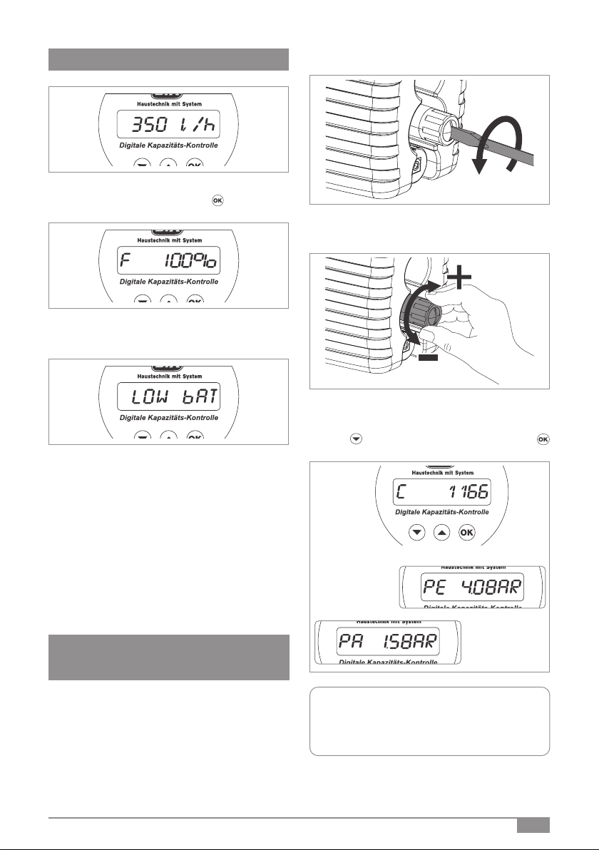
A conductivity sensor and pressure sensors are already in-
tegrated in the digital capacity control.
The built-in pressure reducer ensures a constant set output
pressure so that the heating system is protected against
unwanted overpressure during the filling process.
Housing made of pressed brass. Internal parts and tundish
made of high-quality plastic and NBR.
The plastic parts and elastomers in contact with the drin-
king water comply with the KTW guideline of the Federal
Environment Agency.
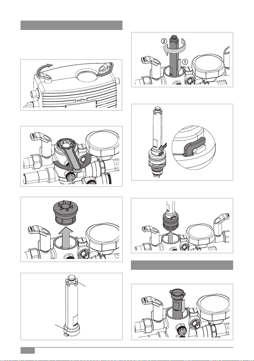
Installation
Mount the wall bracket on the wall.
Make sure that the water supply line is installed in such a
way that stagnation does not occur and that the escaping
water can drain off with a free gradient.
Flush the pipe carefully before installing the connection
centre.
Remove the pressure gauge plug.
Attach the wall bracket at this point of the connection
centre and lock it in place using the screw connections.
Mount the drain valve on the other side.
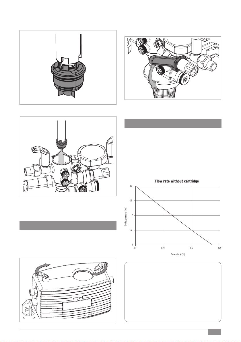
The wall bracket optionally can be mounted on both
sides.
An easily accessible installation location simplifies mainte-
nance and inspection. Make sure that the location is pro-
tected against flooding and frost and is well ventilated. The
drain pipe must be provided with sufficient capacity.
In order to ensure permanent and perfect functioning, we
recommend the installation of a drinking water filter accor-
ding to DIN EN 13443, Part 1 immediately after the water
meter.
The maintenance intervals of the BA backflow preventer
must be observed. For connecting the tundish to the drai-
nage system, the applicable standard DIN EN 12056 must be
observed.