Sysmac Omron NJ Series Instruction Manual

Machine Automation Controller NJ-series
General-purpose Ethernet
Connection Guide
(TCP/IP)
OMRON Corporation
ZW-series Displacement Sensor
P558-E1-01

About Intellectual Property Right and Trademarks
Microsoft product screen shots reprinted with permission from Microsoft Corporation.
Windows is a registered trademark of Microsoft Corporation in the USA and other countries.
EtherCAT®is registered trademark and patented technology, licensed by Beckhoff Automation
GmbH, Germany.
ODVA and EtherNet/IP™ are trademarks of ODVA
Company names and product names in this document are the trademarks or registered
trademarks of their respective companies.

Table of Contents
1. Related Manuals ........................................................................................ 1
2. Terms and Definitions ............................................................................... 2
3. Remarks ..................................................................................................... 3
4. Overview .................................................................................................... 5
5. Applicable Devices and Support Software.............................................. 6
5.1. Applicable Devices............................................................................. 6
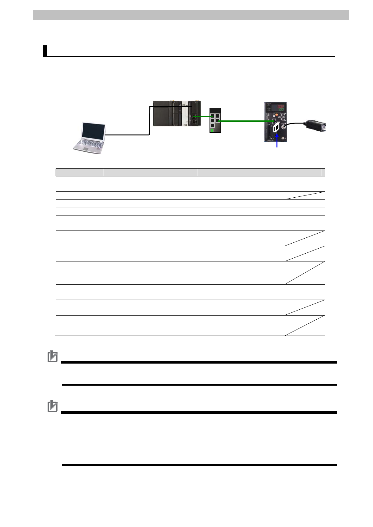
5.2. Device Configuration.......................................................................... 7
6. Ethernet Communications Settings......................................................... 9
6.1. Ethernet Communications Settings.................................................... 9
6.2. Example of Checking Connection .................................................... 10
7. Connection Procedure .............................................................................11
7.1. Work Flow .........................................................................................11
7.2. Setting Up the Displacement Sensor ............................................... 12
7.3. Setting Up the Controller.................................................................. 19
7.4. Checking the Ethernet Communications .......................................... 27
8. Initialization Method................................................................................ 30
8.1. Initializing the Controller................................................................... 30
8.2. Initializing the Displacement Sensor ................................................ 30
9. Program.................................................................................................... 31
9.1. Overview .......................................................................................... 31
9.2. Destination Device Command.......................................................... 35
9.3. Error Detection Processing .............................................................. 39
9.4. Variables .......................................................................................... 42
9.5. ST Program...................................................................................... 47
9.6. Timing Charts................................................................................... 64
9.7. Error Process ................................................................................... 70
10. Revision History .................................................................................. 74

1.Related Manuals
1
1. Related Manuals
The table below lists the manuals related to this document.
To ensure system safety, make sure to always read and heed the information provided in all
Safety Precautions, Precautions for Safe Use, and Precaution for Correct Use of manuals for
each device which is used in the system.
Cat.No. Model Manual name
W500 NJ501-[][][][]
NJ301-[][][][]
NJ-series CPU Unit Hardware User's Manual
W501 NJ501-[][][][]
NJ301-[][][][]
NJ-series CPU Unit Software User's Manual
W506 NJ501-[][][][]
NJ301-[][][][]
NJ-series CPU Unit Built-in EtherNet/IP Port User's Manual
W504 SYSMAC-SE2[][][] Sysmac Studio Version 1 Operation Manual
W502 NJ501-[][][][]
NJ301-[][][][]
NJ-series Instructions Reference Manual
Z322 ZW-C1[] Confocal Fiber Type Displacement Sensor User's Manual
Z332 ZW-CE1[] ZW Series Displacement Sensor (Confocal Fiber Type)
User's Manual

2.Terms and Definitions
2
2. Terms and Definitions
Term Explanation and Definition
IP address Ethernet uses an IP address to perform communications.
The IP address (Internet Protocol address) is an address that is used to
identify a node (host computer or controller, etc.) on Ethernet.
IP addresses must be set and managed so that they do not overlap.
Socket A socket is an interface that allows you to directly use TCP or UDP
functions from the user program. The socket services enable data
exchange with destination nodes. The NJ-series Machine Automation
Controller performs socket communications by using the standard socket
service instructions.
Connect processing/
Accept processing
Open processing is executed on each node to connect the TCP socket.
The open method depends on whether the node is opened as a server or
client.
In this document, the processing executed to open a node as a client is
called "connect processing" and the processing executed to open as a
server is called "accept processing".
Keep-alive function When the keep-alive function is used with TCP/IP socket services, the
keep-alive communications frame is used to check the status of the
connection with the destination node (either a server or client) if there are
no communications during the specified time interval.
Checks are executed at a certain interval, and if there is no response to
any of them then the connection is terminated.
Linger function This is an option for the TCP socket that enables immediate connect
processing using the same port number without waiting until the port
number opens after RST data is sent when the TCP socket closes.
If the linger option is not specified, FIN data will be sent when a TCP
socket is closed, and then approximately 1 minute will be required to
confirm the transmission and perform other closing management with the
destination node. Therefore, it may not be possible to immediately use
TCP sockets with the same port number.

3.Remarks
3
3. Remarks
(1) Understand the specifications of devices which are used in the system. Allow some
margin for ratings and performance. Provide safety measures, such as installing safety
circuit in order to ensure safety and minimize risks of abnormal occurrence.
(2) To ensure system safety, always read and heed the information provided in all Safety
Precautions, Precautions for Safe Use, and Precaution for Correct Use of manuals for
each device used in the system.
(3) The user is encouraged to confirm the standards and regulations that the system must
conform to.
(4) It is prohibited to copy, to reproduce, and to distribute a part of or whole part of this
document without the permission of OMRON Corporation.
(5) The information contained in this document is current as of July 2013. It is subject to
change without notice for improvement.

3.Remarks
The following notation is used in this document.
Indicates a potentially hazardous situation which, if not avoided,
will result in minor or moderate injury, or may result in serious
injury or death. Additionally there may be significant property
damage.
Indicates a potentially hazardous situation which, if not avoided,
may result in minor or moderate injury or in property damage.
Precautions for Safe Use
Precautions on what to do and what not to do to ensure safe usage of the product.
Precautions for Correct Use
Precautions on what to do and what not to do to ensure proper operation and performance.
Additional Information
Additional information to read as required.
This information is provided to increase understanding or make operation easier.
Symbol
4

4.Overview
4. Overview
This document describes the procedure for connecting OMRON Corporation’s Displacement
Sensor (ZW series) (hereinafter referred to as the Displacement Sensor) to the NJ-series
Machine Automation Controller (hereinafter referred to as the Controller) via Ethernet, and
provides the procedure for checking their connection.
Refer to the Ethernet communications settings of the prepared Sysmac Studio project file to
understand the setting procedure and key points to connect the devices via Ethernet.
The user program in this Sysmac Studio project file is used to check the Ethernet connection
by sending/receiving the message of “VR (Version information acquisition)” to/from the
destination device.
Prepare the latest Sysmac Studio project file beforehand. To obtain the file, contact your
OMRON representative.
File name VersionName
Sysmac Studio project file
(extension: smc)
OMRON_ZW_ETN(TCP)_EV101.smc Ver.1.01
*Hereinafter, the Sysmac Studio project file is referred to as the “project file”.
The user program in the project file is referred to as the “program”.
This document aims to explain the wiring method and communications settings
necessary to connect the corresponding devices and provide the setting
procedure. The program used in this document is designed to check if the
connection was properly established, and is not designed to be constantly used
at a site. Therefore, functionality and performances are not sufficiently taken into
consideration. When you construct an actual system, please use the wiring
method, communications settings and setting procedure described in this
document as a reference and design a new program according to your
application needs.
5

5.Applicable Devices and Support Software
5. Applicable Devices and Support Software
5.1. Applicable Devices
The applicable devices are as follows:
Manufacturer Name Model Version
NJ-series CPU Unit NJ501-[][][][]
NJ301-[][][][]
OMRON
Confocal Fiber Type
Displacement Sensor
Controller
ZW-C1[]/CE1[]CE1[]T
6
OMRON
Sensor Head ZW-S[][]
Versions listed
in Section 5.2 or
higher versions
OMRON
Additional Information
As applicable devices above, the devices listed in Section 5.2. are actually used in this
document to check the connection. When using devices not listed in Section 5.2, check the
connection by referring to the procedure in this document.
Additional Information
This document describes the procedure to establish the network connection. It does not
provide information about operation, installation nor wiring method of each device.
For details on the above products (other than communication connection procedures), refer
to the manuals for the corresponding products or contact your OMRON representative.
Additional Information
You can connect devices with the versions listed in Section 5.2 or higher versions.
For devices whose versions are not listed in Section 5.2, the versions are not managed or
there is no version restriction.
To connect a device whose model number is not listed in Section 5.2, use the same version
of the device that is listed.

5.Applicable Devices and Support Software
5.2. Device Configuration
The hardware components to reproduce the connection procedure of this document are as
follows:
Manufacturer
USB cable
LAN cable
NJ501-1500
(Built-in EtherNet/IP port)
Personal computer
(Sysmac Studio installed,
OS: Windows 7)
Switching hub
W4S1-05C
ZW-S20
ZW-C15
Name Model Version
OMRON NJ-series CPU Units
(Built-in EtherNet/IP port)
NJ501-1500 Ver.1.03
OMRON Power Supply Unit NJ-PA3001
OMRON Switching Hub W4S1-05C Ver.1.0
OMRON Sysmac Studio SYSMAC-SE2[][][] Ver.1.04
OMRON Sysmac Studio project file OMRON_ZW_ETN(TCP)_
EV101.smc
Ver.1.01
- Personal computer
(OS:Windows7)
-
- USB cable
(USB 2.0 type B connector)
-
- LAN cable (STP (shielded,
twisted-pair) cable of Ethernet
category 5 or higher)
-
OMRON Displacement Sensor
Controller
ZW-C15 Ver.1.000
OMRON Displacement Sensor
Sensor Head ZW-S20
OMRON Calibration ROM (Included with Sensor
Head.)
Precautions for Correct Use
Prepare the latest project file in advance.
To obtain the file, contact your OMRON representative.
Precautions for Correct Use
Update the Sysmac Studio to the version specified in this section or higher version using the
auto update function. If a version not specified in this section is used, the procedures
described in Section 7 and subsequent sections may not be applicable. In that case, use the
equivalent procedures described in the Sysmac Studio Version 1 Operation Manual (Cat.No.
W504).
7

5.Applicable Devices and Support Software
Additional Information
It may not be possible to reproduce the same operation with different devices or versions.
Check the configuration, model and version. If they are different from your configuration,
contact your OMRON representative.
Additional Information
The system configuration in this document uses USB for the connection between the
personal computer and the Controller. For information on how to install the USB driver, refer
to A-1 Driver Installation for Direct USB Cable Connection of the Sysmac Studio Version 1
Operation Manual (Cat.No. W504).
8

6.Ethernet Communications Settings
6. Ethernet Communications Settings
This section describes the specifications of the communication parameters that are set in this
document and outlines the operation.
Additional Information
To perform communications without using the settings described in this section, you need to
modify the program. For information on the program, refer to Section 9. Program.
6.1. Ethernet Communications Settings
The settings required for Ethernet communications are shown below.
6.1.1. Communications Settings between the Controller and the Displacement
Sensor
The setting example below is used to explain the procedure for connecting the Controller to
the Displacement Sensor.
Setting item Controller Displacement Sensor
IP address 192.168.250.1 192.168.250.2
Subnet mask 255.255.255.0 255.255.255.0 (Default)
Gateway ---.---.---.--- 192.168.0.1 (Default)
Port number Automatic allocation
(Set by the program.)
9600 (Default)
Terminator - [CR] (Default)
*In this document, the gateway setting is unnecessary because the connection is made in
the same segment.
*This project file uses the default settings of the keep-alive and linger option functions for
the TCP socket communications (keep-alive: use, linger option: Do not use). Use these
functions according to the system when necessary.
9

6.Ethernet Communications Settings
6.2. Example of Checking Connection
This document shows an example of a Structured Text (ST) program in which the Controller
executes the connect processing, send/receive processing, and close processing on the
Displacement Sensor.
The Controller and Displacement Sensor send and receive the message of “VR (Version
information acquisition). The following figure outlines the operation.
Controller (CPU Unit)
Built-in EtherNet/IP port Ethernet Displacement Sensor
Project file
10
ST Program
IF …. THEN
……….
ELSE
……….
Local_SrcData
Send data
setting area
Connect processin
g
Close processing
Receive data
Send data
Sending/Receiving Ethernet
command
VR (Version information
ac
q
uisition
)
Executing Ethernet
communications command
Socket
communications
function
Local_RecvData
Receive data
storage area

7.Connection Procedure
11
7. Connection Procedure
This section describes the procedure for connecting the Displacement Sensor to the
Controller via Ethernet.
This document explains the procedures for setting up the Controller and Displacement Sensor
from the factory default setting. For the initialization, refer to Section 8 Initialization Method.
7.1. Work Flow
Take the following steps to connect the Displacement Sensor to the Controller via Ethernet.
7.2. Setting Up the Displacement
Sensor
Set up the Displacement Sensor.
↓
7.2.1. Parameter Setting Set the parameters for the Displacement Sensor.
↓
7.3. Setting Up the Controller Set up the Controller.
↓
7.3.1. Starting the Sysmac Studio and
Importing the Project File
Start the Sysmac Studio and import the project file.
↓
7.3.2. Checking the Parameters and
Building
Check the set parameters, execute the program
check on the project data and build the Controller.
↓
7.3.3. Connecting Online and
Transferring the Project Data
Connect online with the Sysmac Studio and transfer
the project data to the Controller.
↓
7.4. Checking the Ethernet
Communications
Execute the program and confirm that Ethernet
communications are normally performed.
↓
7.4.1. Executing the Program and
Checking the Receive Data
Execute the program and confirm that the correct
data are written to the variables of the Controller.

7.Connection Procedure
7.2. Setting Up the Displacement Sensor
Set up the Displacement Sensor.
7.2.1. Parameter Setting
Set the parameters for the Displacement Sensor.
1
Check the keys and display
used to set parameters for the
Displacement Sensor.
Connect the Sensor Head.
Insert the Calibration ROM.
Connect the LAN cable.
Turn ON the power supply to the
Displacement Sensor.
Main display(red)
Sub-display(green)
ZERORST/EST key
Mode switching key
Calibration ROM
Sensor Head
LAN cable
24V power supply
Run indicator(green)
←(LEFT) key ↑(UP) key
→(RIGHT) key ↓(DOWN) key
ZERO/SET key
2
After the startup screen is
displayed, the RUN mode
screen is displayed.
The RUN indicator is lit as
shown on the right.
Hold down the Mode switching
Key for two seconds.
HolddowntheMode switching Key
for two seconds.
3
A confirmation screen for mode
switching is displayed.
Press the ZERO/SET Key.
PresstheZERO/SET Key once.
12

7.Connection Procedure
4
The FUN mode screen is
displayed.
The RUN indicator is not lit as
shown on the right.
Press →(RIGHT) or ←(LEFT)
Key to change the main display
content from SENS to SYSTEM.
Press the ZERO/SET Key.
Pressthe→(RIGHT) or ←(LEFT) Key.
PresstheZERO/SET Key once.
5
SAVE is displayed on the main
display.
Press →(RIGHT) or ←(LEFT)
key to change the main display
content from SAVE to COM.
Press the ZERO/SET Key.
Pressthe→(RIGHT) or ←(LEFT) Key.
PresstheZERO/SET Key once.
6
RS232C is displayed on the
main display.
Press the →(RIGHT) Key and
change the main display content
from RS232C to ETN.
Press the ZERO/SET Key.
Pressthe→(RIGHT) Key once.
PresstheZERO/SET Key once.
13

7.Connection Procedure
7
IPADDR is displayed on the
main display.
Press the ZERO/SET Key.
PresstheZERO/SET Key once.
8
IP1 is displayed on the main
display.
Press the ZERO/SET Key.
Confirm that 192 is displayed on
the sub-display.
*If the setting value is different,
change the value by referring to
steps 11 and 12.
*In this step, you set 192 that is
the first octet of IP address
192.168.250.2.
Press the ZERORST/ESC Key
once. The first screen in this
step is displayed again.
Press the →(RIGHT) Key once.
PresstheZERO/SET Key.
PresstheZERORST/ESC Key.
IP1 is displayed.
Pressthe→(RIGHT) Key once.
9
IP2 is displayed on the main
display.
Press the ZERO/SET Key.
Confirm that 168 is displayed on
the sub-display.
*If the setting value is different,
change the value by referring to
steps 11 and 12.
*In this step, you set 168 that is
the second octet of IP address
192.168.250.2.
Press the ZERORST/ESC Key
once. The first screen in this
step is displayed again.
Press the →(RIGHT) Key once.
PresstheZERO/SET Key once.
PresstheZERORST/ESC Key once.
IP2 is displayed.
Pressthe→(RIGHT) Key once.
14

7.Connection Procedure
10
IP3 is displayed on the main
display.
Press the ZERO/SET Key.
Confirm that 250 is displayed on
the sub-display.
*If the setting value is different,
change the value by referring to
steps 11 and 12.
*In this step, you set 250 that is
the third octet of IP address
192.168.250.2.
Press the ZERORST/ESC Key
once. The first screen in this
step is displayed again.
Press the →(RIGHT) Key once.
PresstheZERO/SET Key once.
PresstheZERORST/ESC Key once.
IP3 is displayed.
Pressthe→(RIGHT) key once.
11
IP4 is displayed on the main
display.
Press the ZERO/SET Key.
The default value is displayed
on the sub-display.
Press the ZERO/SET Key.
The sub-display content
changes, allowing you to
change the value.
Select a digit whose value you
want to change by pressing the
→(RIGHT) or ←(LEFT) Key.
You can change the value of a
blinking digit.
Change the value by pressing
the ↑(UP) or ↓(DOWN) Key.
Change to 000002.
PresstheZERO/SET Key once.
Pressthe→(RIGHT) or ←(LEFT) Key.
Pressthe↑(UP) or ↓(DOWN) Key.
15

7.Connection Procedure
12
000002 is displayed on the
sub-display.
Press the ZERO/SET Key.
2 is displayed on the
sub-display.
*In this step, you set 2 that is the
fourth octet of IP address
192.168.250.2.
Press ZERORST/ESC Key
once. The first screen in step 11
is displayed again.
Press the ZERORST/ESC Key
once.
PresstheZERO/SET Key once.
PresstheZERORST/ESC Key once.
IP4 is displayed.
PresstheZERORST/ESC Key once.
16
13
IPADDR is displayed on the
main display.
Press the →(RIGHT) Key once
to change the main display to
SUBNET.
Press the ZERO/SET Key.
Pressthe→(RIGHT) Key once.
PresstheZERO/SET Key once.
14
The main display content
changes to SUB1.
Press the ZERO/SET Key.
255 is displayed on the
sub-display.
Press the ZERORST/ESC Key
once.
PresstheZERO/SET Key once.
PresstheZERORST/ESC Key once.

7.Connection Procedure
15
Press the →(RIGHT) Key and
change the main display content
to SUB2, SUB3 and SUB4.
Press the ZERO/SET Key to
check the setting values.
Check that the values between
SUB2 and SUB4 are as follows:
•SUB2, SUB3: 255
•SUB4:0
*In steps 14 and 15, you set
subnet mask 255.255.255.0.
After checking, press the
ZERORST/ESC Key three
times.
PresstheZERORST/ESC Key three
times.
16
ETN is displayed on the main
display.
Press the →(RIGHT) Key and
change the main display content
to DELIMI.
Press the ZERO/SET Key.
Pressthe→(RIGHT) Key once.
PresstheZERO/SET Key once.
17
Confirm that CR is displayed on
the sub-display.
*If the value is different, change
the value by pressing ↑(UP) or
↓(DOWN).
Hold down the Mode switching
Key for two seconds.
Hold down the Mode switching Key for
two seconds.
Default: CR
<Setting range>
CR/LF/CRLF
17
Other manuals for Omron NJ Series
2
This manual suits for next models
1
Table of contents
Popular Accessories manuals by other brands

GP
GP Universal Power Bank instructions

Kindermann
Kindermann CablePort desk2 80 turn Mounting instructions

Tait
Tait TB8100 Installation and operation manual

StarTech.com
StarTech.com ST1216PRO manual

DAVIS
DAVIS Vantage Pro ISS Retrofit Kit installation instructions

Banner
Banner L-GAGE LTF instruction manual