Profibus IQ plus 800 Assembly instructions

50955
Profibus
®
DP
Indicator Interface
Indicator Interface for IQ plus
®
800/810 and IQ plus
®
310A Indicators
Version 1.0
Installation and
Programming Manual
R
DISCONTINUED

DISCONTINUED

Copyright © 2000 Rice Lake Weighing Systems. All rights reserved. Printed in the United States of America.
Specifications subject to change without notice.
Version 1.0, September 2000
Contents
About This Manual................................................................................................................................... 1
1.0 Introduction.................................................................................................................................. 1
2.0 Installation................................................................................................................................... 2
2.1 Physical Connections . . . . . . . . . . . . . . . . . . . . . . . . . . . . . . . . . . . . . . . . . . . . . . . . . . . . . . . . . . . . 2
2.1.1 Serial Communications Jumpers. . . . . . . . . . . . . . . . . . . . . . . . . . . . . . . . . . . . . . . . . . . . . . . . . . . . . . 3
2.1.2 Serial Connections . . . . . . . . . . . . . . . . . . . . . . . . . . . . . . . . . . . . . . . . . . . . . . . . . . . . . . . . . . . . . . . . 3
2.1.3 Profibus Network Connections . . . . . . . . . . . . . . . . . . . . . . . . . . . . . . . . . . . . . . . . . . . . . . . . . . . . . . . 3
2.1.4 Bus Termination Jumpers. . . . . . . . . . . . . . . . . . . . . . . . . . . . . . . . . . . . . . . . . . . . . . . . . . . . . . . . . . . 3
2.1.5 Installing the 20 mA Current Loop Option . . . . . . . . . . . . . . . . . . . . . . . . . . . . . . . . . . . . . . . . . . . . . . . 3
2.2 DIP Switch Configuration. . . . . . . . . . . . . . . . . . . . . . . . . . . . . . . . . . . . . . . . . . . . . . . . . . . . . . . . . . 4
2.3 LED Indicators. . . . . . . . . . . . . . . . . . . . . . . . . . . . . . . . . . . . . . . . . . . . . . . . . . . . . . . . . . . . . . . . . . 6
2.3.1 External LEDs. . . . . . . . . . . . . . . . . . . . . . . . . . . . . . . . . . . . . . . . . . . . . . . . . . . . . . . . . . . . . . . . . . . . 6
2.3.2 Onboard LEDs . . . . . . . . . . . . . . . . . . . . . . . . . . . . . . . . . . . . . . . . . . . . . . . . . . . . . . . . . . . . . . . . . . . 6
2.4 Indicator Setup . . . . . . . . . . . . . . . . . . . . . . . . . . . . . . . . . . . . . . . . . . . . . . . . . . . . . . . . . . . . . . . . . 7
2.4.1 IQ plus 310A Configuration. . . . . . . . . . . . . . . . . . . . . . . . . . . . . . . . . . . . . . . . . . . . . . . . . . . . . . . . . . 7
2.4.2 IQ plus 800/810 Configuration . . . . . . . . . . . . . . . . . . . . . . . . . . . . . . . . . . . . . . . . . . . . . . . . . . . . . . . 7
3.0 Profibus Commands..................................................................................................................... 8
3.1 Integer (20-bit) Commands . . . . . . . . . . . . . . . . . . . . . . . . . . . . . . . . . . . . . . . . . . . . . . . . . . . . . . . . 8
3.1.1 Integer Command Formats. . . . . . . . . . . . . . . . . . . . . . . . . . . . . . . . . . . . . . . . . . . . . . . . . . . . . . . . . . 8
3.1.2 Integer Commands. . . . . . . . . . . . . . . . . . . . . . . . . . . . . . . . . . . . . . . . . . . . . . . . . . . . . . . . . . . . . . . . 9
3.2 Floating Point (32-bit) Commands . . . . . . . . . . . . . . . . . . . . . . . . . . . . . . . . . . . . . . . . . . . . . . . . . . 11
3.2.1 Floating Point Commands. . . . . . . . . . . . . . . . . . . . . . . . . . . . . . . . . . . . . . . . . . . . . . . . . . . . . . . . . . 12
3.3 Status Data . . . . . . . . . . . . . . . . . . . . . . . . . . . . . . . . . . . . . . . . . . . . . . . . . . . . . . . . . . . . . . . . . . . 12
3.4 Command Examples. . . . . . . . . . . . . . . . . . . . . . . . . . . . . . . . . . . . . . . . . . . . . . . . . . . . . . . . . . . . 13
3.4.1 Retrieve Net Weight Data (20-bit) . . . . . . . . . . . . . . . . . . . . . . . . . . . . . . . . . . . . . . . . . . . . . . . . . . . . 13
3.4.2 Retrieve Net Weight Data (32-bit) . . . . . . . . . . . . . . . . . . . . . . . . . . . . . . . . . . . . . . . . . . . . . . . . . . . . 13
3.4.3 Send Setpoint Value (32-bit) . . . . . . . . . . . . . . . . . . . . . . . . . . . . . . . . . . . . . . . . . . . . . . . . . . . . . . . . 14
3.4.4 Read Setpoint Value (32-bit) . . . . . . . . . . . . . . . . . . . . . . . . . . . . . . . . . . . . . . . . . . . . . . . . . . . . . . . . 14
4.0 Appendix.................................................................................................................................... 15
4.1 Troubleshooting. . . . . . . . . . . . . . . . . . . . . . . . . . . . . . . . . . . . . . . . . . . . . . . . . . . . . . . . . . . . . . . . 15
4.2 Profibus Indicator Interface GSD File . . . . . . . . . . . . . . . . . . . . . . . . . . . . . . . . . . . . . . . . . . . . . . . . 16
4.3 Profibus Indicator Interface Specifications . . . . . . . . . . . . . . . . . . . . . . . . . . . . . . . . . . . . . . . . . . . . 17
Profibus Indicator Interface Limited Warranty...................................................................................... 18
DISCONTINUED

ii
Profibus DP Indicator Interface Installation and Programming Manual
DISCONTINUED
Introduction
1
About This Manual
This manual provides information needed to install
and use the Rice Lake Weighing Systems ProÞbus
¨
Indicator Interface. The ProÞbus Indicator Interface
allows IQ plus
¨
800/810 and IQ plus 310A indicators
to communicate with a ProÞbus master device using
the ProÞbus-DP communications standard.
1
The ProÞbus Indicator Interface is housed inside the
NEMA 4X stainless steel indicator enclosure to
permit use in washdown environments.
This manual applies to the following software
versions:
¥ ProÞbus Indicator Interface, Version 1.0
¥ IQ plus 800/810, Version 3.1
¥ IQ plus 310A, Version 5.0
Some procedures described in this
manual require work inside the indicator
or Profibus Indicator Interface
enclosure. These procedures are to be
performed by qualified service
personnel only.
Authorized distributors and their employees
can view or download this manual from the
Rice Lake Weighing Systems distributor site
at
www.rlws.com
.
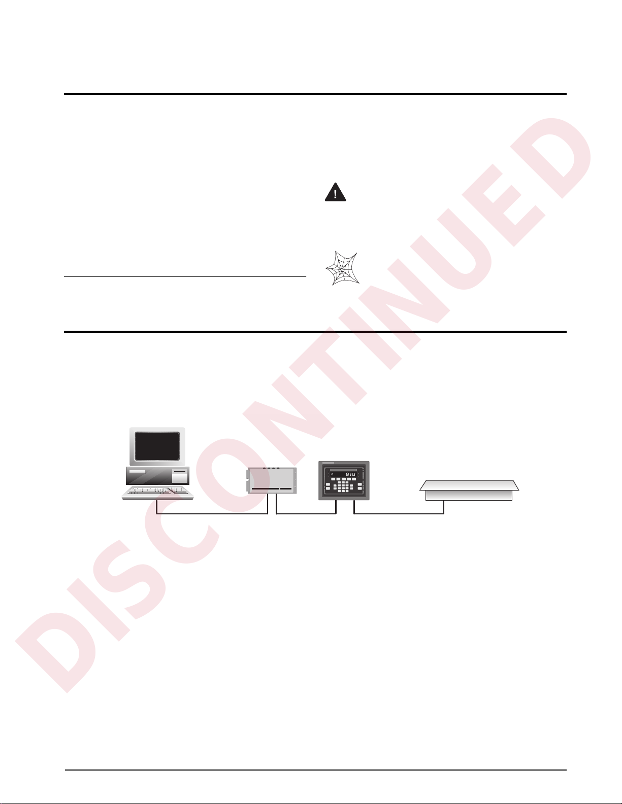
1.0 Introduction
The ProÞbus Indicator Interface provides full control of indicator functions to the PLC programmer and allows
indicator weight and status data to be returned to the ProÞbus DP network. A diskette containing the GSD Þle
used to conÞgure the master device is supplied with the ProÞbus Indicator Interface (see Section 4.2 on page 16).
The following Þgure shows an example of the ProÞbus Indicator Interface used to connect an IQ plus 800/810
indicator to the master device on a ProÞbus DP network.
The ProÞbus Indicator Interface supports two sets of commands: 20-bit integer commands and 32-bit ßoating
point commands (see Section 3.0 on page 8). Both sets are designed for use in demand mode: the master device
sends a command to the ProÞbus Indicator Interface to request information from or pass data to the indicator; the
indicator responds with weight data, status information, or an acknowledgement that the command was executed.
For applications that do not require the capablilities provided by these commands, the ProÞbus Indicator
Interface can be used with the indicator in stream mode. In stream mode, the Display Status command provides
fast, continuous acquisition of indicator weight and status data.
1. Profibus
®
is a registered trademark of Profibus International.
Warning
ZERO NET
GROSS TARE UNITS PRINT
0
.
ENTER
8
79
5
46
2
13
SCALE
#
NEW
L.D.
DISP
ROC
DISP
ACCUM
DATE
TIME/
DISP POINT
SET
CLEAR
Profibus Master Device
Profibus
Indicator Interface IQ plus 810
Scale Platform
DISCONTINUED

2
Profibus Indicator Interface Installation and Programming Manual
2.0 Installation
The ProÞbus Indicator Interface is designed to be mounted on a wall or other vertical surface, with the four status
LEDs on top and the cable connections at the bottom. Before mounting the unit, attach the communications
cables, select the termination resistance, and set the conÞguration DIP switches as described in the following
sections.
2.1 Physical Connections
Initial setup and conÞguration of the ProÞbus Indicator Interface requires opening the Interface enclosure. The
enclosure cover uses 16 screws to ensure proper seating of the cover gasket. Use the torquing pattern shown in
Figure 2-1 to prevent deformation of the gasket when removing and replacing the cover. Torque screws to 15
in-lb when replacing the cover.
Figure 2-1. Torquing Pattern for ProÞbus Indicator Interface Enclosure
Figure 2-2 shows the layout of the ProÞbus Indicator Interface logic board. The following sections describe DIP
switch conÞguration and cable connections to the PLC and indicator.
Figure 2-2. ProÞbus Indicator Interface Logic Board Layout
1
2
3
4
5
6
7
8
9
11
13
10
12
1415
16
U13
C14
C15
U11
1
R3
R4
R5
R6
R7
R68
R69
R70
U3
U12
R71
R73
R72
R74
J2
R2 U2
R19
R27
U14
R76
R77
R78
C19 C3
C5
R29
U4
R28
C4
1
ISOPWR1
U15
C17
R75
C16
R79
C18
C20
R21
R20
R1
R8 U1
R26
C1
C2
U5
CLK1
R25
R24
R22
R23
R31 C6
R38
R39
U6
1
J1
R37
R36
R35
R33
R30
R42
R49
R43
R44
R45
R46
R47
R48
R40
R41
R80
C21
R32
R34
R81
C22 U18 U19
U8
C23
U20
C25C26 C24
C28
J6
R86
R85
R84
C30
C31
C35
C32
C27
C9
C8
U9
R67A1
R67
R66
R66A1
C10
R83
R82A1
R82 C29
U22
RT1
C11
U10
R87A1
R87B1
C13
1
J3
C12
R87
R88
C33
C34
VR1
R57
R56
R55
R54
R53
R52
R62
R61
R60
R59
R58
R50
R51
R63
R64
R65
OUTPUT
PRxD
PTxD
ERROR
RxD
TxD
RxD
20mA/RS485
RS-232
RICE LAKE WEIGHING SYSTEMS
1
1
GND
+5V
TEST
3.3V
20mA
RS-232
1
RS-485
4100 4200
R11
R12
R13
R14
R15
R10
R9
R16
R17
R18
SW1
SW3
JMP3
JMP4
R92
R93
R91
ANALOG
GND
SW2
+5V
GND
RS-232 / TxD
CTS
RTS
+20mA OUT
–20mA OUT
+20mA IN
RESET1
DC/DC Converter J5 Serial Communications
EPROM
20mA Chips
LED connector
GND
GND
J4
Profibus
Communications
GND
12345678
ON
12345678
ON
12345678
ON
U16 U17
U21
U7
RS-232 / RxD
–20mA IN
CABLE
TERMINATION
Install JMP3 &JMP4
DISCONTINUED

Installation
3
2.1.1 Serial Communications Jumpers
Two jumpers, labeled
RxD
and
OUTPUT
, determine
whether the ProÞbus Indicator Interface uses RS-232
or 20 mA current loop for serial communications with
the indicator. Leave the jumpers in the position shown
in Figure 2-4 for RS-232 communications; move both
jumpers to the
20mA
position if using the 20 mA
current loop option. See Figure 2-2 on page 2 for
board location of the jumpers.
Figure 2-3. RxD and OUTPUT Jumpers, Showing Jumper
Positions for RS-232 Communications
2.1.2 Serial Connections
Serial communications connections to the indicator
are made at connector J5 on the ProÞbus board (see
Figure 2-2 on page 2 for board location of J5).
Figure 2-4 shows the J5 connector layout for the
ProÞbus Indicator Interface. Table 2-1 shows the
serial communications connections between the
ProÞbus Indicator Interface and the IQ plus 800/810
indicators; Table 2-2 shows the serial communications
connections between the ProÞbus Indicator Interface
and the IQ plus 310A indicators.
Figure 2-4. Serial Communications Connections
Table 2-1. IQ plus 800/810 Indicator-to-ProÞbus Serial
Port Pin Assignments
NOTE:
The 20 mA current loop interface connection
requires that the 20 mA option be installed in both the
ProÞbus Indicator Interface and the IQ plus 800/810.
See Section 2.1.5 for information about installing the
20 mA option.
Table 2-2. IQ plus 310A Indicator-to-ProÞbus Serial Port
Connections
2.1.3 Profibus Network Connections
Connections to the ProÞbus network are made at
connector J4 on the ProÞbus board (see Figure 2-2 on
page 2 for board location of J4). Table 2-3 shows the
connections from J4 connector on the ProÞbus board
to the DB-9 ProÞbus connector.
2.1.4 Bus Termination Jumpers
If the ProÞbus Indicator Interface is the last device on
the network bus, install jumpers JMP3 and JMP4 on
the ProÞbus board (see Figure 2-2 on page 2 for
jumper locations).
2.1.5 Installing the 20 mA Current Loop Option
The ProÞbus Indicator Interface can communicate
with IQ plus 800/810 indicators using the 20 mA
current loop interface if the option is installed in both
the Interface and the indicator. Installing the 20 mA
option disables RS-232 communications.
IQ plus 800/810 Indicator Profibus Indicator Interface
Pin Signal Signal J5 Pin
J7-11 RS232/TxD RS232/RxD 8
J7-12 RS232/GND RS232/GND 2
J7-9 RS232/RxD RS232/TxD 3
J7-10 –20mA/TxD –20mA/RxD 8
J7-12 +20mA/TxD +20mA/RxD 7
J7-8 –20mA/RxD –20mA/TxD 6
J7-7 +20mA/RxD +20mA/TxD 5
RxD
20mA
RS-232
OUTPUT
20mA
RS-232
1
J5
Serial Communications
+5V
GND
RS-232 / TxD
CTS
RTS
+20mA OUT
–20mA OUT
+20mA IN
RS-232 / RxD
–20mA IN
IQ plus 310A Indicator Profibus Indicator Interface
Pin Signal Signal J5 Pin
J4-1 RS232/TxD RS232/RxD 8
J4-2 RS232/GND RS232/GND 2
J4-3 RS232/RxD RS232/TxD 3
Profibus
NetworkDB-9
Pin Signal
Profibus
Indicator
Interface J4
Connector Pin
1 Shield ground/Earth ground 10
2
Blank pin
2
3 Profibus B 3
4 RTS 4
5 Power supply common 5
6 +5V 6
7
Blank pin
7
8 Profibus A 8
9
Blank pin
9
NC NC/chassis ground 1
NOTE: If connecting the DB-9 shield ground (pin 1) to J4 pin
10 causes ground loop problems, disconnect.
Table 2-3. ProÞbus Network Connections
DISCONTINUED

4
Profibus Indicator Interface Installation and Programming Manual
Use the following procedure to install the 20 mA
option for the ProÞbus Indicator Interface:
1. Disconnect ProÞbus Indicator Interface from
power source.
2. Remove enclosure cover.
3. Install 20 mA chips in sockets U16 and U17
on ProÞbus board (see Figure 2-2 on page 2).
4. Make cable connections to pins 5Ð8 on
connector J5 (see Table 2-1).
5. Replace enclosure cover and tighten screws
using torquing pattern shown in Figure 2-1.
6. Reconnect power to ProÞbus Indicator
Interface.
2.2 DIP Switch Configuration
Two banks of DIP switches are used to conÞgure the
ProÞbus Indicator Interface for communication
between the indicator and the network. Figure 2-5
shows the switch assignments for SW1ÐSW3.
Figure 2-5. DIP Switch Assignments
SW2 SW1
MSBLSB
Indicator
Data Rate
Stop Bits
Indicator
Type
Reserved
Profibus Address
Parity
12345678
ON
12345678
ON
DISCONTINUED

Installation
5
Profibus Address
Switches SW1-1 through SW1-8 are used to set the
address of the ProÞbus Indicator Interface. Use
Table 2-4 to select the correct switch settings for the
network address. Note that setting a switch OFF acts
as a logical Ò0Ó and that SW1-1 represents the least
signiÞcant bit (LSB) of the network address.
The conÞgured address equals the sum of the values
of the switches set on. For example, to set a network
address of 19, SW1 switches would be set as shown in
Table 2-5:
For hexadecimal addressing, SW1 functions as shown in Table 2-6. Repeating the example from Table 2-4,
decimal 19 is hexadecimal 13: Switch 1-5 (1 in byte 1) and switches 1-2 and 1-1 (2+1 = 3 in byte 0) would be set
on for an address of hex 13.
Indicator Type
Switches SW2-1 and SW2-2 set the type of indicator
attached to the ProÞbus Indicator Interface.
Indicator Data Rate
Switches SW2-3 and SW2-4 set the data rate used for
communications between the indicator and the
ProÞbus Indicator Interface. Set to 9600 bps for the IQ
plus 310A.
Stop Bits
Switch SW2-5 sets the number of stop bits used to
communicate with the indicator. Set SW2-5 OFF for
one stop bit, ON for two stop bits.
Parity
Switches SW2-6 and SW2-7 set the type of parity
used to communicate with the indicator.
Switch Decimal Value if Switch=ON
1-1 1
1-2 2
1-3 4
1-4 8
1-5 16
1-6 32
1-7 64
1-8 128
Table 2-4. SW1 Switch Values for Network Addressing
Switch ON Value Switch State Value
1-11ON1
1-22ON2
1-3 4 OFF 0
1-4 8 OFF 0
1-5 16 ON 16
1-6 32 OFF 0
1-7 64 OFF 0
1-8 128 OFF 0
Sum of ON switch values:
19
Table 2-5. SW1 Example for Network Address 19
Switch
1-8 1-7 1-6 1-5 1-4 1-3 1-2 1-1
Byte 1 Byte 0
84218421
2
7
2
6
2
5
2
4
2
3
2
2
2
1
2
0
Table 2-6. Switch Values for Hexadecimal Addressing
Data Rate (bps) SW2-1 SW2-2
IQ plus 310A OFF OFF
IQ plus 800/810 ON OFF
Table 2-7. Indicator Type Switch Settings
Data Rate (bps) SW2-3 SW2-4
9600 OFF OFF
19200 OFF ON
Table 2-8. Network Data Rate Switch Settings
Parity SW2-6 SW2-7
NONE OFF OFF
EVEN OFF ON
ODD ON OFF
Table 2-9. Parity Switch Settings
DISCONTINUED

6
Profibus Indicator Interface Installation and Programming Manual
2.3 LED Indicators
2.3.1 External LEDs
Four LEDs on the top of the ProÞbus Indicator Interface enclosure provide status information for the operator.
Table 2-10 summarizes the function of the LEDs. See Section 4.1 on page 15 for more troubleshooting
information.
2.3.2 Onboard LEDs
Two groups of three amber LEDs on the ProÞbus board itself provide additional diagnostic ßexibility:
¥ LEDs labeled
PTxD
,
ERROR
, and
PRxD
are mounted next to the J1 LED connector
¥ LEDs labeled
RxD
,
TxD
, and
3.3V
are mounted behind the OUTPUT jumper
Table 2-11 summarizes the function of these LEDs:
LED Color Function
Power Red
On when external power applied
ERROR Red
System error
On when communications between indicator
and Profibus Indicator Interface is lost Check that baud rates configured at Profibus
Indicator Interface and at the master are the same
Check wiring at J5 connector
RxD Green
Blinks when data is received from the indicator May appear to be on steady when indicator is
streaming data
TxD Green
Blinks when data is sent to the indicator
Table 2-10. ProÞbus Indicator Interface LED indicators
LED Function
PTxD
Profibus communications status. Same functions as backplate LEDs.
ERROR
PRxD
RxD
Blinks when data received from indicator. Off indicates no transmission from the indicator to the Profibus
Indicator Interface.
TxD
Blinks when data sent to the indicator. Off indicates no transmission from the Profibus Indicator Interface to the
indicator.
3.3V
Off indicates possible failure of 3.3V or 5V power supply.
Table 2-11. Onboard Diagnostic LEDs
DISCONTINUED

Installation
7
2.4 Indicator Setup
Indicators communicate with the ProÞbus Indicator Interface using the indicator EDP port. Both IQ plus 310A
and IQ plus 800/810 indicators support RS-232 communications. The IQ plus 800/810 indicators can also use 20
mA current loop communications providing the 20 mA option is installed in both the indicator and the ProÞbus
Indicator Interface.
2.4.1 IQ plus 310A Configuration
Table 2-12 shows the conÞguration parameters recommended for the IQ plus 310A indicator to communicate
with the ProÞbus Indicator Interface. See the IQ plus 310A Installation & Service Manual for detailed
information about conÞguring the indicator.
2.4.2 IQ plus 800/810 Configuration
Table 2-13 shows the conÞguration parameters recommended for the IQ plus 800/810 indicators to communicate
with the ProÞbus Indicator Interface. See the IQ plus 800/810 Installation Manual for detailed information about
conÞguring the indicator.
IQ plus 310A Configuration Settings Notes
EDP MODE DEMAND Required
BAUD 9600 Must match DIP switch selection on Profibus Indicator Interface
BITS 8 NONE Required
TERMIN CR
EOL DLY 0 MS
FORMAT REMOTE
CASE UPPER
RESPOND STATUS
PRINTER MODE TICKET Specify TICKET mode to improve indicator performance
SETUP KEYBRD DISABLE Select to disable front panel (blind operation)
TARE RS REGULT Required
TARE FN AUTO
Table 2-12. IQ plus 310A ConÞguration Settings
IQ plus 800/810 Configuration Settings Notes
CONFIG FEATURE A/B ON A/B FEATURE is enabled at the factory for indicators ordered
with the Remote I/O option. If the A/B FEATURE is OFF, call
RLWS for information about activating the feature.
SERIAL EDP BAUD 9600 or 19200 Must match DIP switch selection on Profibus Indicator
Interface
BITS 8 NONE Required
TERMIN CR
EOL DLY 0 MS
ABSTRM OFF
STREAM OFF
Table 2-13. IQ plus 800/810 ConÞguration Settings
DISCONTINUED
8Profibus Indicator Interface Installation and Programming Manual
3.0 Profibus Commands
The ProÞbus Indicator Interface uses 20-bit integer and 32-bit ßoating point commands to send and receive data
from the indicator. This section describes the input and output data formats, commands, and status bit
assignments, and provides examples of 20-bit and 32-bit command usage.
3.1 Integer (20-bit) Commands
3.1.1 Integer Command Formats
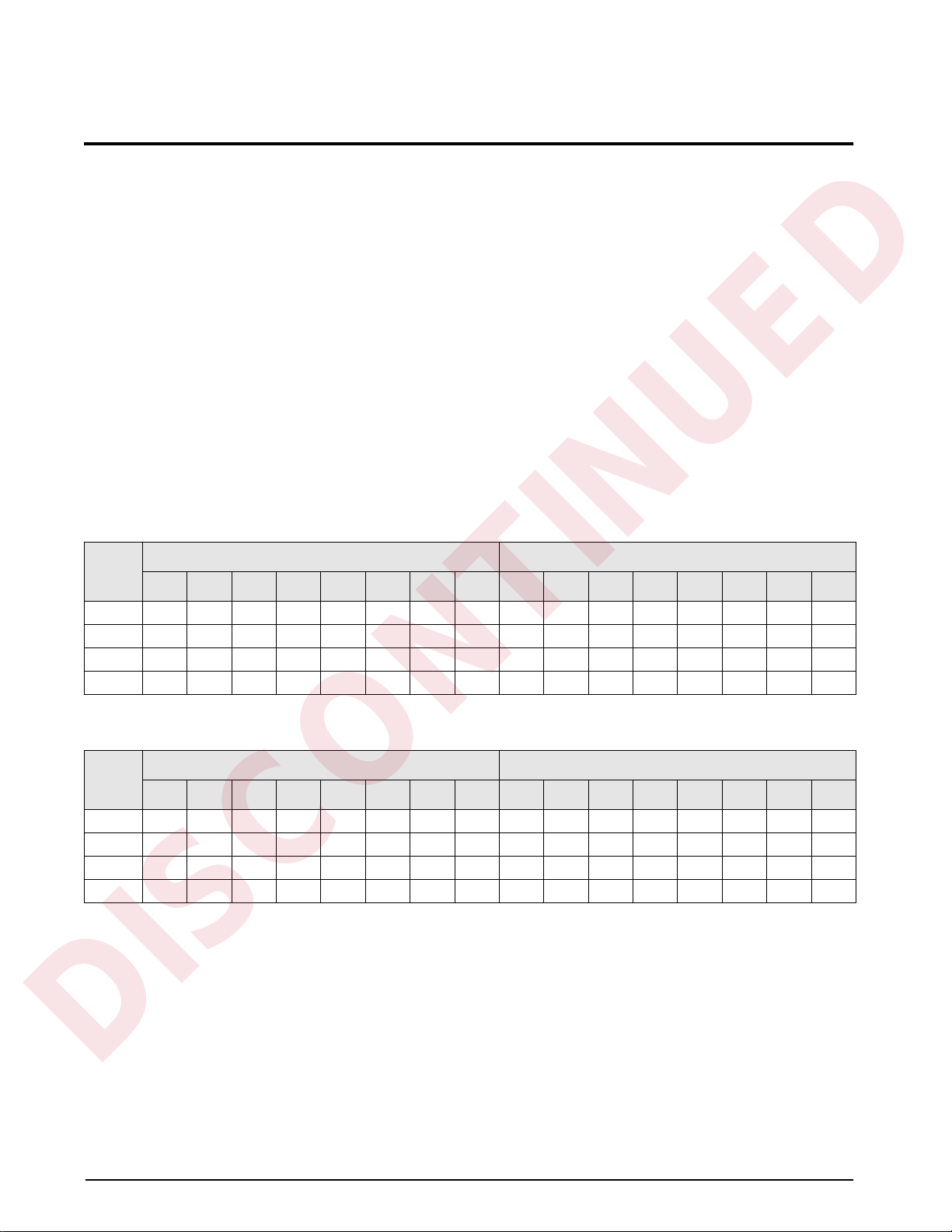
Tables 3-1 and 3-2 show the data formats used to send and receive 20-bit integer commands. Bit assignments as
follows:
R Reserved
s00-s08 Status data
cccc cccc Command number
v00–v19 20-bit integer value
See Table 3-3 on page 9 for a listed of supported commands; see Section 3.3 on page 12 for status bit
assignments.
NOTE: Integer commands return no decimal point information to the master. For example, a value of 750.1
displayed on the indicator is returned to the master as 7501.
Bit
Byte 1 Byte 0
15 14 13 12 11 10 9 8 7 6 5 4 3 2 1 0
Word0RRRRRRRRcccccccc
Word1RRRRRRRRRRRRRRRR
Word2RRRRRRRRRRRRv19v18v17v16
Word 3 v15 v14 v13 v12 v11 v10 v09 v08 v07 v06 v05 v04 v03 v02 v01 v00
Table 3-1. ProÞbus 20-bit Integer Output Format
Bit
Byte 1 Byte 0
15 14 13 12 11 10 9 8 7 6 5 4 3 2 1 0
Word0RRRRRRRRRRRRRRRR
Word 1 s15 s14 s13 s12 s11 s10 s09 s08 s07 s06 s05 s04 s03 s02 s01 s00
Word2RRRRRRRRRRRRv19v18v17v16
Word 3 v15 v14 v13 v12 v11 v10 v09 v08 v07 v06 v05 v04 v03 v02 v01 v00
Table 3-2. ProÞbus 20-bit Integer Input Format
DISCONTINUED

Profibus Commands 9
3.1.2 Integer Commands
Table 3-3 lists the integer commands that can be speciÞed for IQ plus 800/810 and IQ plus 310A indicators. Valid
commands for each indicator are indicated by a check mark (Ö). The number representing the indicator command
is sent in the lower byte of word 0 (bits 0Ð7).
Hex Decimal Command 800/810 310A
00 00 Display Status ÖÖ
01 01 Display Channel 0 Ö
02 02 Display Channel 1 Ö
03 03 Display Channel 2 Ö
04 04 Display Channel 3 Ö
05 05 Display Channel 4 Ö
06 06 Display Gross Weight ÖÖ
07 07 Display Net Weight ÖÖ
09 09 Acquire Tare ÖÖ
0A 10 Primary Units Ö
0B 11 Secondary Units Ö
0C 12 Select Pounds Ö
0D 13 Select Kilograms Ö
0E 14 Print Request ÖÖ
10 16 Clear Accumulator, Channel 0 Ö
11 17 Clear Accumulator, Channel 1 Ö
12 18 Clear Accumulator, Channel 2 Ö
13 19 Clear Accumulator, Channel 3 Ö
14 20 Clear Accumulator, Channel 4 Ö
15 21 Clear Tare ÖÖ
16 22 Return Gross, Channel 0 Ö
17 23 Return Gross, Channel 1 ÖÖ
18 24 Return Gross, Channel 2 Ö
19 25 Return Gross, Channel 3 Ö
1A 26 Return Gross, Channel 4 Ö
1B 27 Return Net, Channel 0 Ö
1C 28 Return Net, Channel 1 ÖÖ
1D 29 Return Net, Channel 2 Ö
1E 30 Return Net, Channel 3 Ö
1F 31 Return Net, Channel 4 Ö
20 32 Return Tare, Channel 0 Ö
21 33 Return Tare, Channel 1 ÖÖ
22 34 Return Tare, Channel 2 Ö
23 35 Return Tare, Channel 3 Ö
24 36 Return Tare, Channel 4 Ö
25 37 Return Currrent Display ÖÖ
26 38 Batch Start Ö
28 40 Batch Pause Ö
Table 3-3. IQ plus 800/810 and IQ plus 310A Integer Commands
DISCONTINUED

10 Profibus Indicator Interface Installation and Programming Manual
29 41 Batch Reset Ö
2A 42 Batch Status Ö
2B 43 Zero ÖÖ
2C 44 Enter Tare ÖÖ
2E 46 Return Accumulator, Channel 0 Ö
2F 47 Return Accumulator, Channel 1 Ö
30 48 Return Accumulator, Channel 2 Ö
31 49 Return Accumulator, Channel 3 Ö
32 50 Return Accumulator, Channel 4 Ö
33 51 Return Rate of Change, Channel 0 Ö
34 52 Return Rate of Change, Channel 1 Ö
35 53 Return Rate of Change, Channel 2 Ö
36 54 Return Rate of Change, Channel 3 Ö
37 55 Return Rate of Change, Channel 4 Ö
38 56 Return Peak, Channel 0 Ö
39 57 Return Peak, Channel 1 Ö
3A 58 Return Peak, Channel 2 Ö
3B 59 Return Peak, Channel 3 Ö
3C 60 Return Peak, Channel 4 Ö
3D 61 Push Weight to Accumulator, Channel 0 Ö
3E 62 Push Weight to Accumulator, Channel 1 Ö
3F 63 Push Weight to Accumulator, Channel 2 Ö
40 64 Push Weight to Accumulator, Channel 3 Ö
41 65 Push Weight to Accumulator, Channel 4 Ö
42 66 Lock Indicator Front Panel Ö
43 67 Unlock Indicator Front Panel Ö
44 68 Set Digital Output ON Ö
45 69 Set Digital Output OFF Ö
Hex Decimal Command 800/810 310A
Table 3-3. IQ plus 800/810 and IQ plus 310A Integer Commands (Continued)
DISCONTINUED

Profibus Commands 11
3.2 Floating Point (32-bit) Commands
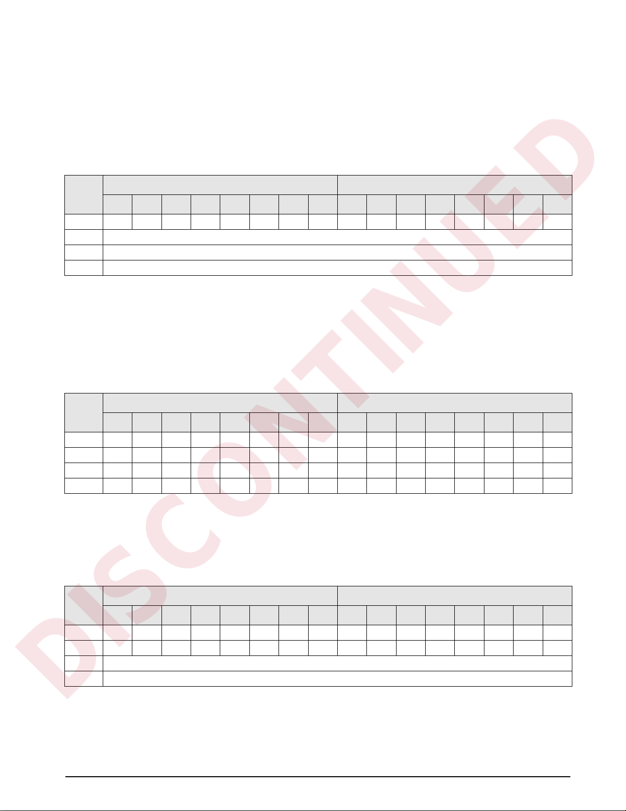
Tables 3-4 and 3-5 show the data formats used to send and receive 32-bit ßoating point commands. Bit
assignments are as follows:
R Reserved
s00-s08 Status data
n00-n07 Channel number or setpoint number
c cccc cccc Command number
v00–v31 32-bit floating point value
See Table 3-6 on page 12 for a list of supported commands; see Section 3.3 on page 12 for status bit assignments.
NOTE: Floating point commands support decimal point information with no special handling.
Bit
Byte 1 Byte 0
15 14 13 12 11 10 9 8 7 6 5 4 3 2 1 0
Word0RRRRRRRccccccccc
Word1RRRRRRRRn07n06n05n04n03n02n01n00
Word 2 v31 v30 v29 v28 v27 v26 v25 v24 v03 v22 v21 v20 v19 v18 v17 v16
Word 3 v15 v14 v13 v12 v11 v10 v09 v08 v07 v06 v05 v04 v03 v02 v01 v00
Table 3-4. ProÞbus 32-bit Floating Point Output Format
Bit
Byte 1 Byte 0
15 14 13 12 11 10 9 8 7 6 5 4 3 2 1 0
Word0RRRRRRRccccccccc
Word 1 s15 s14 s13 s12 s11 s10 s09 s08 s07 s06 s05 s04 s03 s02 s01 s00
Word 2 v31 v30 v29 v28 v27 v26 v25 v24 v03 v22 v21 v20 v19 v18 v17 v16
Word 3 v15 v14 v13 v12 v11 v10 v09 v08 v07 v06 v05 v04 v03 v02 v01 v00
Table 3-5. ProÞbus 32-bit Floating Point Input Format
DISCONTINUED

12 Profibus Indicator Interface Installation and Programming Manual
3.2.1 Floating Point Commands
Table 3-6 lists the ßoating point commands that can be speciÞed for IQ plus 800/810 and IQ plus 310A
indicators. Valid commands for each indicator are indicated by a check mark (Ö). The number representing the
indicator command is sent in word 0 (bits 0Ð8).
3.3 Status Data
Table 3-7 shows the remote function status data format; Table 3-8 shows the batch status data format. The batch
status format is used in response to command 42 (hex 2A), Batch Status.
Hex Decimal Command 800/810 310A
101 257 Set Tare ÖÖ
102 258 Read Tare ÖÖ
103 259 Read Accumulator Ö
104 260 Read Gross ÖÖ
105 261 Read Net ÖÖ
106 262 Set Setpoint Value Ö
107 263 Set Setpoint Hysteresis Ö
108 264 Set Setpoint Bandwidth Ö
109 265 Set Setpoint Preact Ö
10A 266 Read Setpoint Value Ö
10B 267 Read Setpoint Hysteresis Ö
10C 268 Read Setpoint Bandwidth Ö
10D 269 Read Setpoint Preact Ö
10E 270 Set Batching State Ö
Table 3-6. IQ plus 800/810 and IQ plus 310A Floating Point Commands
Bit
Status Data
Value=0 Value=1
s00 No Error Error
s01 Tare not entered Tare entered
s02 Not zero Center of zero
s03 Weight OK Weight invalid
s04 Standstill In motion
s05 Primary units Secondary units
s06 Tare not acquired Tare acquired
s07 Gross weight Net weight
s08 Channel 0 or 1 Channel 2, 3, or 4
s09 Not used
s10
s11 Positive weight Negative weight
s12 Not used
s13
s14
s15
Table 3-7. Run Status Word Format
Bit
Status Data
Value=0 Value=1
s00 No Error Error
s01 DIGIN 3 = OFF DIGIN 3 = ON
s02 DIGIN 2 = OFF DIGIN 2 = ON
s03 DIGIN 1 = OFF DIGIN 1 = ON
s04 Batch paused Batch not paused
s05 Batch running Batch not running
s06 Batch not stopped Batch stopped
s07 Not used
s08
s09
s10
s11
s12
s13
s14
s15
Table 3-8. Batch Status Word Format
DISCONTINUED
Profibus Commands 13
3.4 Command Examples
This section provides examples of 20-bit integer and 32-bit ßoating point commands used to send and receive
indicator data.
3.4.1 Retrieve Net Weight Data (20-bit)
Table 3-9 shows a binary representation of the 20-bit output data used to retrieve net weight from the indicator
using command 28. The output format includes only the command number, in byte 0 of word 0 (0001 1100 =
hex 1C, decimal 28).
Table 3-10 shows the input data returned by the previous command:
¥ The status bits in word 1 (see Section 3.3 on page 12) show that a tare has been performed and the
indicator is in net mode.
¥ Weight data is returned in word 3 (0000 0111 1101 0101 = hex 07D5 = decimal 2005). Assuming the
indicator is conÞgured to display pounds, with one decimal position, the net weight is interpreted as
200.5 LB.
3.4.2 Retrieve Net Weight Data (32-bit)
Table 3-11 shows a binary representation of the 32-bit output data used to retrieve net weight from channel 2 of
an IQ plus 800/810using command 261. The output format includes the command number, in byte 0 of word 0
(0001 0001 1100 = hex 105, decimal 261), the channel number (0100, decimal 2) in the lower byte of word 1.
Bit
Byte 1 Byte 0
15 14 13 12 11 10 9 8 7 6 5 4 3 2 1 0
Word0RRRRRRRR00011100
Word 1 Not used
Word 2 Not used
Word 3 Not used
Table 3-9. 20-bit Integer Output to Send Command 28, Return Net Weight, Channel 1
Bit
Byte 1 Byte 0
15 14 13 12 11 10 9 8 7 6 5 4 3 2 1 0
Word0RRRRRRRRRRRRRRRR
Word10000000011000010
Word2RRRRRRRR00000000
Word30000011111010101
Table 3-10. 20-bit Integer Input with Returned Net Weight Data
Bit
Byte 1 Byte 0
15 14 13 12 11 10 9 8 7 6 5 4 3 2 1 0
Word00000000100000101
Word10000000000000100
Word 2 Not used
Word 3 Not used
Table 3-11. 32-bit Floating Point Output to Send Command 261, Read Net Weight
DISCONTINUED

14 Profibus Indicator Interface Installation and Programming Manual
Table 3-12 shows the input data returned by the previous command:
¥ The command number for which the data is returned is included in word 0 (command 261).
¥ The status bits in word 1 (see Section 3.3 on page 12) show that a tare has been performed and the
indicator is in net mode.
¥ Weight data returned in words 2 and 3 must be copied into a ßoating point storage location before being
read.
3.4.3 Send Setpoint Value (32-bit)
Table 3-13 shows a decimal representation of the
32-bit output data used to set the value of setpoint 1 to
100.5. Note that the setpoint value is not readable as
100.5: The value data must be copied to words 2 and 3
from a ßoating point storage location.
After sending the command, use the Read Setpoint
Value command (decimal 266) to verify that the
indicator received the correct setpoint value.
3.4.4 Read Setpoint Value (32-bit)
Table 3-14 shows the output data used to read the
value of setpoint 1.
Table 3-15 shows the data returned by the previous
command. Again, the value data returned in words 2
and 3 must be copied into a ßoating point storage
location to be read.
Bit
Byte 1 Byte 0
15 14 13 12 11 10 9 8 7 6 5 4 3 2 1 0
Word00000000100000101
Word10000000011000010
Word20100001111111010
Word31101100110011010
Table 3-12. 32-bit Floating Point Input with Returned Net Weight Data
Word Value (Decimal) Description
0 262 Command number
1 1 Setpoint number
2 17097 Setpoint value (MSW)
3 0 Setpoint value (LSW)
Table 3-13. 32-bit Floating Point Output to Send Command
262, Send Setpoint Value
Word Value (Decimal) Description
0 262 Command number
1 1 Setpoint number
20Not used
30Not used
Table 3-14. 32-bit Floating Point Output to Send Command
266, Read Setpoint Value
Word Value (Decimal) Description
0 266 Command number
10Not used
2 17097 Setpoint value (MSW)
3 0 Setpoint value (LSW)
Table 3-15. 32-bit Floating Point Input with Returned
Setpoint Value Data
DISCONTINUED

Appendix 15
4.0 Appendix
4.1 Troubleshooting
The following section provides information for diagnosing communications problems between the indicator and
the ProÞbus master. The status of the LEDs on the ProÞbus Indicator Interface can be used to diagnose the
general area of difÞculty, as shown in Table 4-1.
If there is no communication between the indicator and the master device, do the following:
1. Ensure DIP switches on the ProÞbus board are set correctly (see Section 2.2 on page 4).
2. Power down,then power up the ProÞbus Indicator Interface.
3. Ensure the ProÞbus master device is set to send a command to the slave. Commands are listed in
Section 3.0 on page 8.
4. Check the OUTPUT and RxD jumpers to ensure they are set for RS-232 communications (see
Section 2.1.1 on page 3).
5. Check the wiring from the indicator to connector J5 on the ProÞbus board (see Section 2.1.2 on page 3).
6. Ensure the indicator conÞguration is correct.
7. Check that the master is set up correctly to communicate with the slave device.
8. On the ProÞbus board, ensure that the 3.3V LED is lit. If it is not, check connector J6 for a loose or
incorrect connection (see Figure 2-2 on page 2). If the LED is still not lit, replace the ProÞbus Indicator
Interface power supply.
9. Locate EPROM U7 found in the middle of the ProÞbus board (see Figure 2-2 on page 2). Ensure that the
chip is seated by pressing down on the chip.
10. Check that the connector J4 on the ProÞbus board is Þrmly connected.
11. If no problems are found in the checks above, replace the ProÞbus board.
Symptom Possible Cause
POWER LED not lit No power to Profibus board. Ensure connector J6 on the Profibus
board is properly seated.
RxD LED flashes constantly; TxD LED not lit Indicator is streaming data to the Profibus slave. Check indicator
configuration. See Section 2.4 on page 7 for indicator configuration
information.
TxD LED flashes every two seconds; RxD LED not lit Serial connection between the indicator and the Profibus Indicator
Interface is not correct. See Section 2.4 on page 7 for indicator
configuration information.
Table 4-1. Troubleshooting Symptoms Indicated by LEDs
DISCONTINUED

16 Profibus Indicator Interface Installation and Programming Manual
4.2 Profibus Indicator Interface GSD File
;=================================================================
; GSD-File for Profibus Indicator Interface
; Rice Lake Weighing Systems
;
; Version V0.3
;
; Date : 01.02.2000
; File : RLWS088C.GSD
;=================================================================
#Profibus_DP
; <Unit-Definition-List>
GSD_Revision = 1 ; Needed to tell that this file works with text readers.
Vendor_Name = "Rice Lake Weighing Systems "; Used to tell whose file this is.
Model_Name = "Profibus Indicator Interface "; Tells what is supported by this
file.
Revision = "V1.1 "; Tells what version GSD file this is.
Ident_Number = 0x088B; Seperates one manufacturers different part numbers.
Protocol_Ident = 0 ; Profibus DP protocol
Station_Type = 0 ; This is a slave device
FMS_supp = 0 ; No FMS support
Hardware_Release= "Rev B "; Tells that this works with hardware Rev B, not required.
Software_Release= "Rev1.00"; Tells that this file works with Software release 1.00, not
required.
9.6_supp = 1 ; These baud rates with a "1" are supported, "0" is not
19.2_supp = 1
93.75_supp = 1
187.5_supp = 1
500_supp = 1
45.45_supp = 1
1.5M_supp = 1
3M_supp = 1
6M_supp = 1
12M_supp = 1
MaxTsdr_9.6 = 60 ; This is the time delay needed after a message is sent.
MaxTsdr_19.2 = 60
MaxTsdr_93.75 = 60
MaxTsdr_187.5 = 60
MaxTsdr_500 = 100
MaxTsdr_45.45 = 120
MaxTsdr_1.5M = 150
MaxTsdr_3M = 250
MaxTsdr_6M = 450
MaxTsdr_12M = 800
Redundancy = 0 ; Redundancy not supported
Repeater_Ctrl_Sig = 2 ; Repeater control signal TTL RTS (2) not connected (0).
24V_Pins = 0 ; 24 V pins not connected.
Implementation_Type ="SPC3"; Slave-Specification:
Freeze_Mode_supp =0 ; Freeze mode is not supported.
Sync_Mode_Supp = 0 ; Sync-mode is not supported.
Auto_Baud_supp = 1 ; Auto baud rate detection supported.
Set_Slave_Add_Supp = 0 ; Supports function Set_Slave Add
Min_Slave_Intervall = 100 ; Sets the value (multiples of 100us) between two slave poll
cycles of the same slave
Modular_Station = 1 ; Indicates that this is a modular device (device can be set up
multiple ways.)
Max_Module = 1 ; indicates the number of ways -1 that this can be set up.
Max_Input_Len = 128 ; Indicates the max number of bytes of a modular station.
Max_Output_Len = 128 ; Indicates the maximum number of output bytes of a modular
station.
Max_Data_Len = 256 ; Indicates the maximum number of data transferred in bytes to or
from the device.
; Unit_Diag_Bit(0) = ; Usable to indicate status or error messages (bitwise).
Fail_Safe = 0;1 ; Tells if fail safe mode is supported (1) or not (0).
; Max_Diag_Data_Len= 29
Modul_Offset = 0 ; Tells how many to add to "module" number for module numbers.
Slave_Family = 3@TdF@OTHER; USED BY COM PROFIBUS TO SET UP IN SLAVE MODULES MENU
; Below useable for RS485 Adresses?
DISCONTINUED
This manual suits for next models
1
Table of contents
Other Profibus Accessories manuals

Popular Accessories manuals by other brands


Hytronik
Hytronik HMW35 Installation and instruction manual

AMX
AMX IRX-SM+ quick start guide

AuVerte
AuVerte GK10 Series quick start guide

Crivit
Crivit SC-1358 Instructions for use

Freescale Semiconductor
Freescale Semiconductor KITMPR03xEVM quick start guide

Becker
Becker SC431-II Assembly and operating instructions